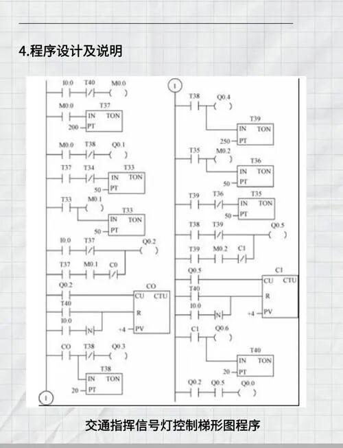
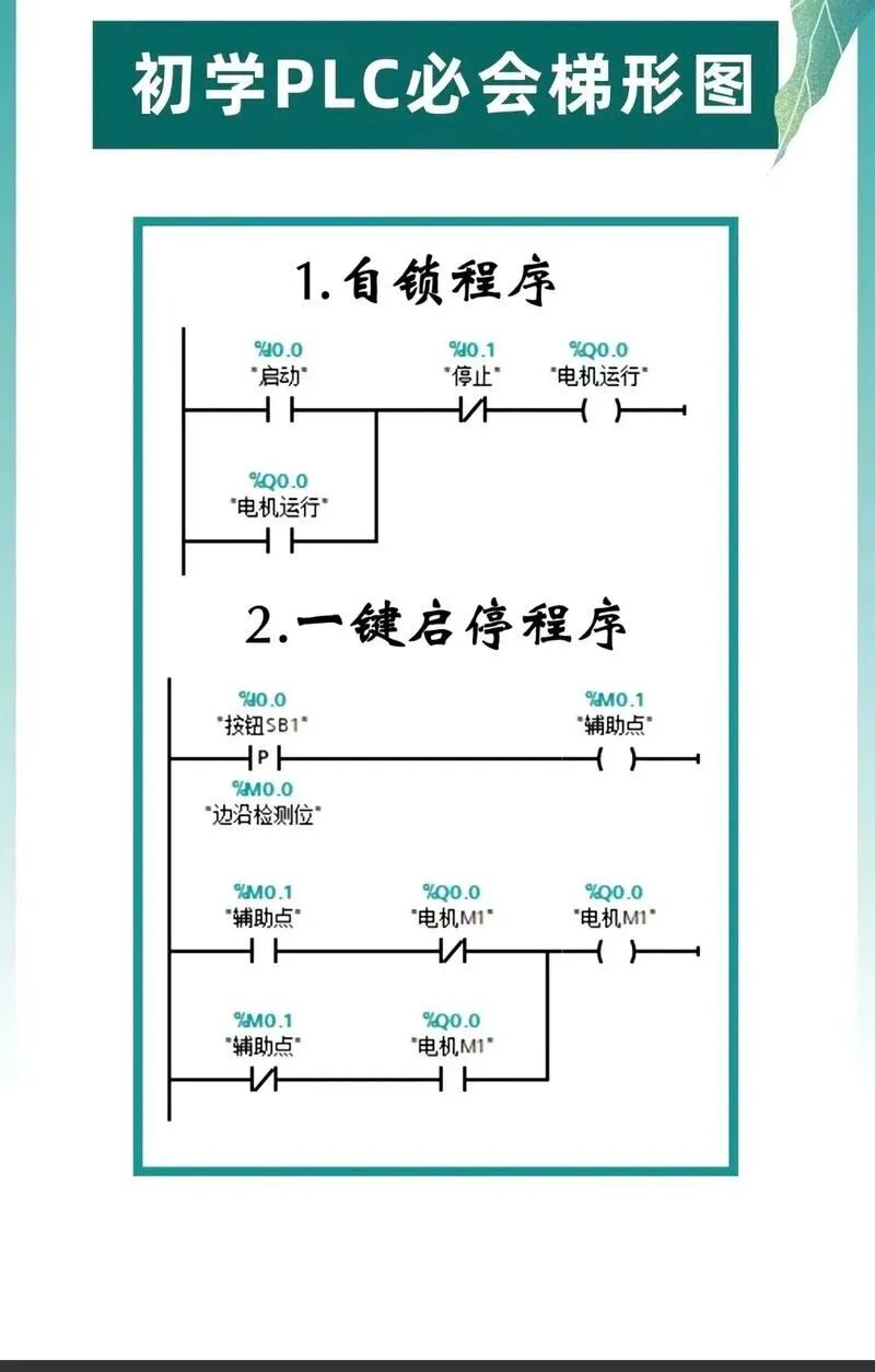
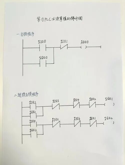
Hello everyone, I am Xiao Chen. Today, let’s discuss a common issue that many PLC beginners encounter: why does a large number of ladder diagrams make the program seem bloated and difficult to maintain?In fact, while ladder diagrams are intuitive, programming purely with basic instructions is indeed inefficient.Mastering Function Block programming can make your PLC programs more concise, readable, and easier to maintain, effectively doubling your development efficiency! Below, I will introduce the 5 most commonly used PLC function blocks that can enhance efficiency.
1. Timer Function Block: More Than Just Timing
Basic Concept
The Timer Function Block is one of the most fundamental and commonly used function blocks in PLCs. It works like a timer in our daily lives, starting to count when specified conditions are met and triggering actions after reaching a preset time.
Common types of timers include:
- TON: On-Delay Timer (most commonly used)
- TOF: Off-Delay Timer
- TP: Pulse Timer
Ladder Diagram Example
For example, a basic On-Delay Timer ladder diagram is as follows:
|--[Input_1]--+--[TON]--+--[Output_1]--|
              |         |
              |  PT=5s  |
              |  ET=?s  |
              +---------+
Code Example (using Siemens S7-1200)
// Declare Timer
#Timer_1 : TON;

// Set and execute timer
#Timer_1(IN := "Input_Signal",    // Input signal, starts timing when TRUE
         PT := T#5S,              // Preset time 5 seconds
         Q => "Output_Signal",    // Output when timing is complete
         ET => "Elapsed_Time");   // Elapsed time
Practical Application Case
In a simple conveyor control system, we need to start the next action 5 seconds after an item passes the sensor to prevent false triggering due to the item not fully passing through.
However, a more advanced use is to combine multiple timers to achieve complex logic. For example, in a filling machine project, I used multiple timers to coordinate the timing of valve openings and closings, achieving filling accuracy down to the millisecond level.
Common Issues and Solutions
Issue 1: The timer is inaccurate, always having a deviation of several milliseconds.Solution: This is normal; the PLC scan cycle affects timing accuracy. For situations requiring high precision timing, you can:
- Use high-speed counters or special high-precision timing functions
- Consider reserving error compensation time in programming
Issue 2: The timer does not trigger.Solution: Check if the IN input remains TRUE.Many beginners make the mistake of having the input signal only momentarily active, rather than continuously active..
2. Counter Function Block: A Tool for Data Statistics

Basic Concept
The Counter Function Block is used to count the number of occurrences of events, just like counting with your fingers. It is widely used in production counting, cycle control, and other scenarios.
Common types include:
- CTU: Up Counter (counts up from 0 to a preset value)
- CTD: Down Counter (counts down from a preset value to 0)
- CTUD: Up/Down Counter (can count both ways)
Ladder Diagram Example
|--[Count_Pulse]--+--[CTU]--+--[Full_Signal]--|
                  |         |
|--[Reset]--------+ CV=?    |
                  | PV=100  |
                  +---------+
Code Example (using Mitsubishi FX series)
// C0 is the counter, K100 is the preset value
LD X000      // Count pulse input
COUNT C0 K100
LD C0        // When count reaches preset value
OUT Y000     // Output signal

LD X001      // Reset signal
RST C0       // Reset counter
Practical Application Case
On a packaging production line, each time a photoelectric sensor detects a product, the counter increments by 1. When the count reaches the preset packaging quantity (e.g., 12), the output signal controls the sorting mechanism to push this batch of products into the packaging box.
Once, I encountered an interesting case: a factory’s counter was always inaccurate. After investigation, it was found that the sensor’s installation position was too shaky, causing signal jitter that led to a product being counted multiple times. The solution was to add a 20ms delay filter to the counting signal, which immediately resolved the issue.
Common Issues and Solutions
Issue 1: The count value is abnormal, sometimes over-counting or under-counting.Solution:
- Check if the sensor is securely installed
- Add debounce delay
- Optimize sensor position to avoid vibration sources
Issue 2: The counter does not reset to zero after resetting.Solution: In many PLCs, the reset signal needs to have a certain pulse width. Ensure the duration of the reset signal is long enough, usually at least one scan cycle.
3. Shift Register Function Block: The Manager of Data Flow
Basic Concept
The Shift Register works like a data conveyor belt; with each shift pulse, all data moves one position in one direction. This is an excellent tool for handling sequential operations.
Imagine a line of people; as one person moves forward, everyone in the line moves forward, and the person at the front leaves the line. The shift register works in this way.
Ladder Diagram Example
|--[Shift_Pulse]--+--[SHL]--+--|
                  |         |
|--[Data_In]------+ IN      |
                  | OUT     |
                  +---------+
Code Example (using Omron CP series)
// Using Shift Register Function
LD  BOOL#1         // Input data (1 or 0)
SHL D100, D100, 1  // Shift D100 left by 1 position, result stored back in D100
LD  D100.00        // Access the least significant bit of D100
OUT Y0             // Output to Y0

Practical Application Case
In an assembly line with 8 stations, products pass through each station sequentially. When a product enters the first station, the corresponding position in the shift register is set to 1; as the product moves forward, the 1 also moves in the register. By checking which position in the shift register is 1, we can know which station the product is currently at.
Once, while handling a 6-station light bulb testing system, the shift register was very helpful. Each light bulb entering the system would sequentially go through energizing, preheating, brightness testing, color temperature testing, cooling, and grading at six stations. By using the shift register, I only needed to look at the position of 1 in the register to know the processing stage of each light bulb, greatly simplifying the program logic.
Common Issues and Solutions
Issue 1: Shift errors, data confusion.Solution:
- Ensure the shift pulse triggers only once to avoid multiple triggers
- Add interlock logic to prevent repeated shifting
- Regularly check and reset the state of the shift register
Issue 2: Shifted data is lost.Solution: Shift operations typically discard the farthest data. If this data is important, it should be saved to other variables before shifting.
4. Comparator Function Block: The Precise Manager of Data Judgement
Basic Concept
The Comparator Function Block is used to compare the size relationship between two values and output a logical signal based on the comparison result. It is like “comparing sizes” in our daily lives, but more precise and reliable.
Common comparison operations include:
- Greater than (>)
- Less than (<)
- Equal to (=)
- Greater than or equal to (>=)
- Less than or equal to (<=)
- Not equal to (<> )
Ladder Diagram Example
|--[Always_ON]--+--[CMP >]--+--[Output_Signal]--|
                |           |
                | A=Temp    |
                | B=30      |
                +-----------+
Code Example (using AB CompactLogix)
// Check if temperature is greater than 30 degrees
GRT(Source_A := Temp_Value,   // First comparison value (temperature)
    Source_B := 30,           // Second comparison value (threshold)
    Dest := Temp_High);       // Comparison result (TRUE indicates temperature > 30)
Practical Application Case
In a temperature control system, we need to decide whether to turn on the heater or cooler based on the current temperature. Using the Comparator Function Block allows for precise control of the system’s operational state:
- Temperature < 18℃ → Turn on heater
- Temperature > 25℃ → Turn on cooler
- 18℃ ≤ Temperature ≤ 25℃ → Maintain current state
Once, in a food processing plant, the production line needed to classify products based on weight. I used a series of Comparator Function Blocks to achieve precise classification into four levels: “less than 300g”, “300-500g”, “500-800g”, and “greater than 800g”, greatly improving sorting efficiency.
Common Issues and Solutions
Issue 1: Floating-point comparisons are not precise.Solution: Floating-point numbers have precision issues, and direct comparisons may not be accurate. It is recommended to use “approximately equal” logic:
// Check if two floating-point numbers are approximately equal
ABS(Value1 - Value2) < 0.0001
Issue 2: Frequent switching of comparison conditions leads to system jitter.Solution: Add hysteresis control (dead zone control), for example:
- Condition to turn on heating: Temperature < 18℃
- Condition to turn off heating: Temperature > 20℃ This can effectively prevent frequent switching near the critical value.
5. PID Control Function Block: The Ultimate Weapon for Process Control

Basic Concept
The PID (Proportional-Integral-Derivative) Control Function Block is a powerful tool for achieving precise process control. It calculates the proportional, integral, and derivative values of the error to output a control quantity, stabilizing the system around the setpoint.
If we compare temperature control to driving a car, then:
- P (Proportional) – Corresponds to seeing the difference between the target speed and the current speed, adjusting the throttle accordingly
- I (Integral) – Corresponds to a long-term low speed, gradually increasing throttle pressure
- D (Derivative) – Corresponds to anticipating approaching the target speed, reducing throttle pressure in advance
Ladder Diagram Example
|--[Always_ON]--+--[PID]--+--[Output_Signal]--|
                |         |
                | SP=50   | // Setpoint
                | PV=?    | // Actual value
                | KP=2.0  | // Proportional gain
                | KI=0.5  | // Integral time
                | KD=0.1  | // Derivative time
                +---------+
Code Example (using Siemens S7-300)
// Call PID controller
CALL "PID_Compact"
     Setpoint    := 50.0    // Set temperature 50 degrees
     Input       := Actual_Temp // Actual temperature input
     Output      := Heat_Output // Heater output (0-100%)
     P_Gain      := 2.0     // Proportional gain
     I_Time      := 20.0    // Integral time (seconds)
     D_Time      := 5.0     // Derivative time (seconds)
Practical Application Case
In a temperature control system for a plastic extruder, the original simple ON/OFF control led to temperature fluctuations of ±5℃, resulting in unstable product quality. After switching to PID control, the temperature stabilized within ±0.5℃ of the setpoint, significantly improving product quality.
Once, while debugging a temperature control system for a chemical reactor, I found it difficult to stabilize the temperature regardless of how I adjusted the PID parameters. Later, I discovered the issue was due to the temperature sensor being too close to the heating element, causing measurement lag. After relocating the sensor to a more reasonable position, the system stabilized quickly.This teaches us that PID control is not just a parameter issue, but also a hardware layout issue..
Common Issues and Solutions
Issue 1: PID parameters are difficult to tune.Solution:
- Use the Ziegler-Nichols tuning method
- Start with P control, gradually increase KP until the system exhibits small oscillations
- Then introduce I control, and finally add D control
- Remember: P determines response speed, I eliminates steady-state error, and D suppresses overshoot.
Issue 2: Large overshoot during system startup.Solution:
- Implement a soft start strategy
- Set output limits
- Consider using a “ramp function” to gradually change the setpoint to the target value
Conclusion: The Power of Function Blocks
These 5 function blocks may seem simple, but when used in combination in actual engineering, they can solve the vast majority of automation control problems. Mastering them means mastering the core tools of PLC programming.
Practical Suggestions:
- Start with simple applications, such as using timers to implement a delay control
- Progressively try combining counters and shift registers for sequential control
- Master how to use comparators to build complex judgment logic
- Challenge yourself to use PID control for a temperature system, observing the system’s response under different parameters
- Try creating custom function blocks to encapsulate commonly used functions
Safety Reminder: Always pay attention to safety during debugging, especially when controlling actual devices. It is recommended to first test programs in a simulation environment and confirm correctness before connecting to actual devices. Be especially cautious when adjusting PID parameters, as improper settings may lead to severe oscillations and damage to equipment.
These function blocks are like LEGO bricks; once you master them, you can build complex and powerful control systems. I believe that through continuous practice, your PLC programming efficiency will significantly improve!