Performance Comparison Between HPM6P81 and TI C2000 F28P5x
1. Purpose and Significance of Testing
- • Evaluate the performance differences between the two MCUs in applications such as motor control and power management, providing reference for selection.
- • Explore the significance of C2000.
- • Thanks to the enthusiastic contributions of developer starry-m (https://github.com/starry-m)
• If you are interested in other articles by Xianji developers, you can check – Xianji Developer Column
2. Overview of Comparison Projects
| Comparison Item | HPM6P81 | TI C2000 F28P550SJ9 |
| Clock Frequency | 600 MHz (RISC-V Core) | 150 MHz (C28x Core) |
| Architecture | 2 X RISC-V + FFA Co-processor | C28x + CLA Co-processor |
| Memory | 1MB Flash (expandable XIP) / 800KB SRAM | 1088KB Flash / 133KB RAM |
| Communication Interfaces | 4xCAN / 9xUART / 4xSPI / 4x I2C / 1 HS USB | 2 x CAN / 3xUART / 2xSPI / 2x I2C / USB |
| Analog Peripherals | 2M x 16bit ADC (4M x 12bit) / DAC / Comparator | 5 x 3.9MSPS 12bit ADC / DAC / CMPSS |
| Motor Control Resources | 4x8CHHR-PWM100ps | 12(24)xePWM-150ps / QEP / CMPSS / HALL |
| Supported Algorithm Libraries | HPM Motor Control SDK | MOTOR/Digital Power / C2000Ware / DSP Library |
| Development Toolchain | HPM SDK / Segger Embedded Studio | Code Composer Studio (CCS) |
| Ethernet Support | Supports Gigabit Ethernet (GMAC) | No Ethernet support |
| External Storage Interface | 1 x 16bit 166MHz 1 x XPI | None |
3. Computing Power and DSP Performance Testing
| Item | HPM6P81 | F28P55x | Notes |
| coremark | CoreMark/MHz: 2894.09 / 600 ≈ ⭐️4.82⭐️ | coremark porting unsuccessful | |
| Toolchain | rv32imac_zicsr_zifencei_multilib_b_ext-win (gcc version 13.2.0) | ||
| coremark | CoreMark/3481.09 / 600 ≈ ⭐️5.80⭐️ | ||
| Toolchain | andes-riscv32-none-elf (gcc version 10.4.0) |
Toolchains and Optimization Levels Used for Testing
| HPM6P81 | F28P55x | Notes | |
| IDE | SEGGER Embedded Studio 8.22a | Code Composer Studio 12.8.1 | |
| Compiler | andes-riscv32-none-elf | ti-cgt-c2000_22.6.1.LTS | |
| C Standard | C99 | C89 | Project default settings |
| Compilation Options | O3 | O2 | Project default settings |
- • Performance testing mainly used examples provided by their respective SDKs to record the complete computation time, and then statistics were compared.
- • The FFT test project for HPM already includes timing by default, while the timing for C2000 is obtained through the debug tick calculation function provided in CCS.
hpm6p81@600MHz
📊 256-point FFT execution time comparison (unit: tick, built type: RAM)
| FFT Method | Precision Type | Algorithm/Type | Execution Direction | Time (tick) | Actual Time (us) |
| Radix-4 FFT | float32 | Radix-4 | FFT | 15406 | 25 |
| Radix-2 FFT | float32 | Radix-2 | FFT | 24246 | 40 |
| Radix-2 FFT | Q31 | Radix-2 | FFT | 18002 | 30 |
| FFA FFT | Q31 | Hardware Accelerated | FFT | 7872 | 13 |
| Radix-4 FFT | float32 | Radix-4 | IFFT | 15890 | 26 |
| Radix-2 FFT | float32 | Radix-2 | IFFT | 24686 | 41 |
| Radix-2 FFT | Q31 | Radix-2 | IFFT | 20442 | 34 |
| FFA FFT | Q31 | Hardware Accelerated | IFFT | 7891 | 13 |
🚀 Speed Comparison (from fastest to slowest)
| Rank | Method Type | Precision | Performance | Function Name |
| 🥇 1 | FFA Accelerated Q31 FFT | Medium | Fastest | hpm_ffa_cfft_q31 |
| 🥈 2 | Radix-2 FFT (float) | High | Very Fast | hpm_dsp_cfft_rd2_f32 |
| 🥉 3 | Radix-2 FFT (Q31) | Medium | Medium | hpm_dsp_cfft_rd2_q31 |
| 🏅 4 | Radix-4 FFT (float) | High | Slow | hpm_dsp_cfft_rd4_f32 |
F28P550SJ9@150MHz:
📊 256-point FFT execution time comparison (unit: tick)
| FFT Method | Precision Type | Algorithm/Type | Execution Direction | Time (tick) | Actual Time (us) |
| CFFT_f32 | float32 | FPU Accelerated | FFT | 11681 | 77 |
| iCFFT_f32 | float32 | FPU Accelerated | IFFT | 12845 | 85 |
| RFFT_f32 | float32 | FPU Accelerated | FFT | 5025 | 33 |
| iRFFT_f32 | float32 | FPU Accelerated | IFFT | 6249 | 41 |
🧠 Comparison of 4 FFT Operations
| Filename | Operation Type | Input Type | Output Type | FFT Direction | Sample Count | Notes |
| dsp_cfft.c | CFFT | Complex (interleaved Re/Im) | Complex Spectrum | FFT | 256 | Standard Complex FFT |
| dsp_rfft.c | RFFT | Real | Symmetric Complex Spectrum | FFT | 256 | Real FFT → unpack |
| dsp_icfft.c | ICFFT | Complex Spectrum (Re/Im) | Complex Waveform | IFFT | 256 | Complex Inverse Transform |
| dsp_irfft.c | IRFFT | Symmetric Complex Spectrum | Real Waveform | IFFT | 256 | Real Inverse Transform (inverse of RFFT) |
🧪 Output Verification Method Comparison
| Verification Item | dsp_cfft.c | dsp_rfft.c | dsp_icfft.c | dsp_irfft.c |
| Re/Im Real Part Verification | ✅ | ✅ | ✅ | ❌ (Real) |
| Magnitude Verification | ✅ | ✅ | ❌ | ❌ |
| Phase Verification | ✅ | ✅ | ❌ | ❌ |
| Output Reconstructed as Real | ❌ | ❌ | ❌ | ✅ |
Summary: This section mainly uses the 256-point complex FFT as the test item, measuring the time taken to run the FFT computation function, all using hardware FPU acceleration. The speed of HPM’s FFA accelerated Q31 FFT can achieve about 5 times that of F28P550SJ9.Note: The data here is based solely on my test results from running the FFT examples, and there may be cases of insufficient testing.
4. Motor Control Performance Testing
PWM frequency and precision, direct data + logic analyzer measurementManual Data: HPM6P81: 100ps F28P550: 150ps
HPM Precision Testing
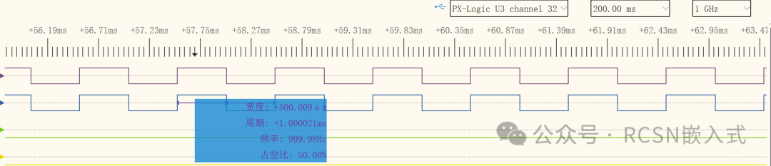
Using the <span>hrpwm_calibrate</span> example program for testing, the above shows two channels of PWM measured with a logic analyzer, and the blue waveform below is the reference channel, where the high level width should be around 500.009us.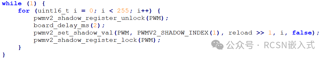
In the program, the low 8 bits of the 32-bit comparison value are updated in polling.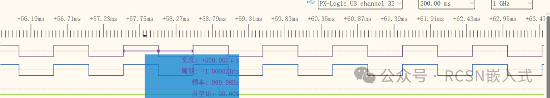
In the above purple waveform, one high level width is around 500.005us.
In the above purple waveform, one high level width is around 500.008us. The HPM manual states the best precision is 0.1ns. The variation I observed is 3ns, but I noticed some irregular changes in the purple waveform (not monotonous), so my logic analyzer may also have errors, but this is the most precise instrument I have (a high-precision oscilloscope is even more unavailable). Seeing this result, there is no need to test the C2000, as the instrument’s precision is insufficient.
Summary: Precision testing requires high-precision instruments, and I lack the experimental conditions to compare.
Signal Link Testing
TI has an application note <span>showing real-time benchmark testing for optimizing signal chains with C2000™ control MCUs</span>, which mentions that testing cannot be solely based on coremark or pure computational performance; the entire acquisition control loop must be considered, including interrupt response, ADC read conversion time, algorithm processing time, and time to write to execute peripherals (PWM).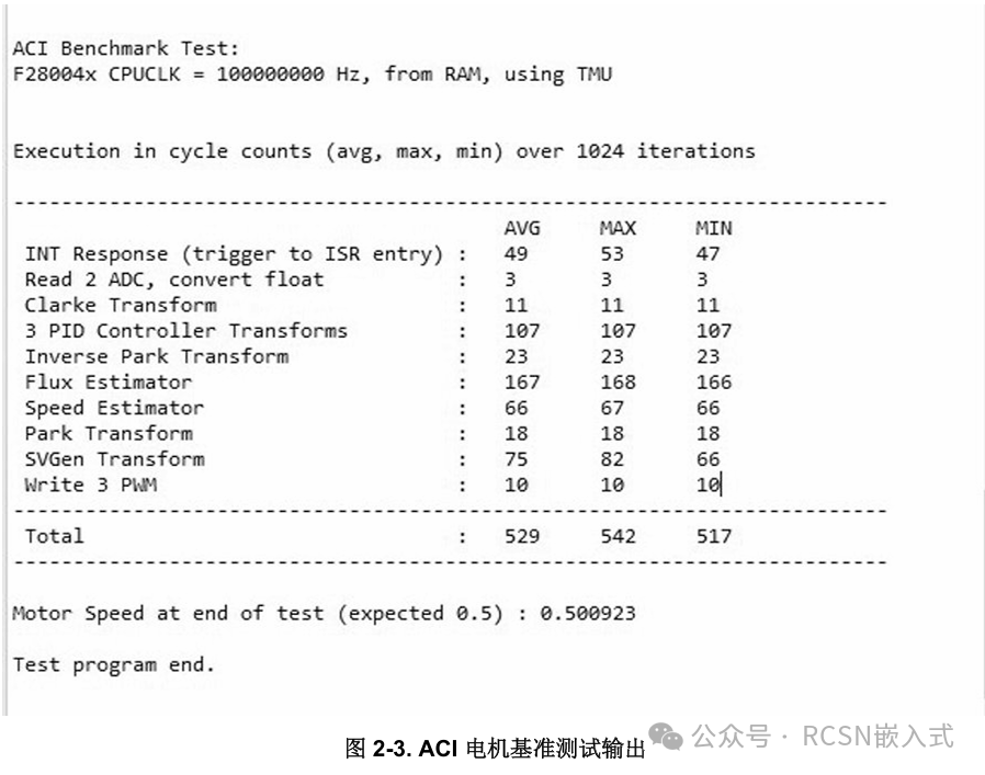
Summary: Testing the time taken for a complete control loop process is significant, but the experimental conditions are not yet complete.
5. Power Control Capabilities
HPM: 4 x 2MSPS 16-bit high-precision ADCs, configurable to 12-bit precision with a conversion rate of up to 4MSPS, with up to 32 analog input channels, supporting differential inputs.C2000: 5 x 3.9MSPS 12-bit ADCs
The sampling rates of the 12-bit ADCs on both sides should be similar. However, the number of channels differs significantly. To make an actual precision comparison, a high-precision signal source is needed, so we will skip this.Summary: I lack the experimental conditions to compare.
6. Communication Interface Performance Comparison
| Comparison Item | HPM6P81 | TI C2000 F28P550 |
| SPI | Up to 80MHz | Up to 37.5MHz |
| USB | 480Mbps | 12Mbps |
| Ethernet | 1000M | No |
| CANFD | 4 channels | 2 channels |
Summary: HPM6P81 has significant advantages over F28P550 in both communication peripheral performance and quantity.
7. Software Support and Usability
HPM: Primarily promotes CMake and Segger Embedded Studio, with SDKs providing unified management of peripheral operations for different chips, allowing for quick chip model migration. User projects only include their own code, reducing redundancy. IO configuration has a Pinmux tool for configuring board-level pin functions. The programming toolchain mainly consists of J LINK GDB and OPENOCD. Although beginners may not be familiar with the CMake development model, they can still use the official project generation tool with the integrated development environment of Segger Embedded Studio.
C2000: TI’s C2000 mainly uses its own Code Composer Studio integrated development environment. The C2000Ware SDK also abstracts different chips, allowing all chips to use the same API for operations. Configuration tools include SysConfig, which completes pin function, peripheral settings, CMD file, and algorithm library configurations, which may be more comprehensive than HPM. However, the CMD configuration files for C2000 are not easy to get started with; often due to their flexibility, they can leave many beginners confused.
Summary: Overall, both sides have decent software support, but for users familiar with microcontroller development, HPM is easier as the basic operations are similar. In contrast, C2000’s different configuration method compared to microcontrollers presents a certain difficulty for beginners (often leading to inexplicable issues).
8. Power Consumption and Thermal Design Analysis
This section is difficult to compare chip power consumption directly as I only have the boards, so the comparison is mainly based on data from the manuals.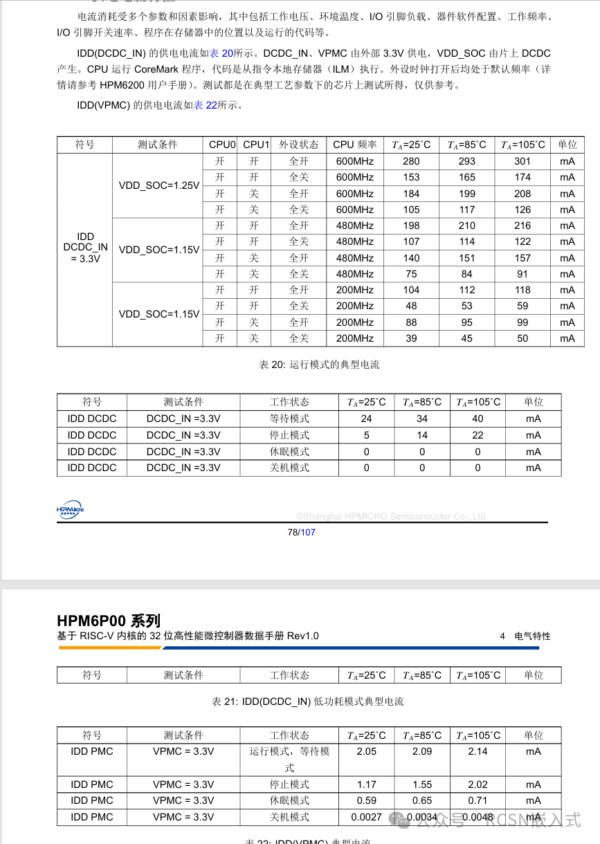
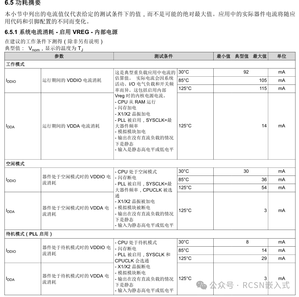
Summary
It can be seen that HPM6P generally has a maximum current of nearly 300 when fully powered, while F28P550 is around 100. Although the current consumption on paper is 3 times higher, the frequency difference is 4 times, and HPM has many peripherals, so this is understandable.