
In the field of electronic design, the PCB selection guide is a core tool for engineers to avoid design risks and optimize product costs. A suitable circuit board, like a solid foundation, directly determines the performance, reliability, and market competitiveness of the final product. This guide aims to provide a systematic PCB selection framework to help engineers make informed decisions amidst the complex parameters and materials.
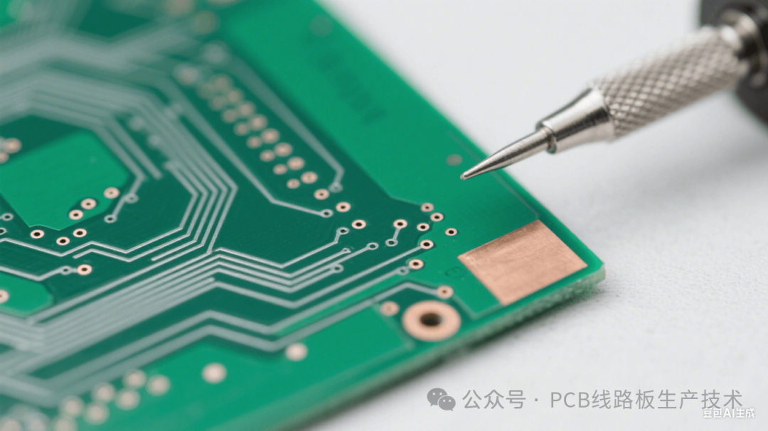
High-speed PCB selection is one of the most challenging aspects of current electronic design. As signal rates enter the GHz era, traditional FR-4 materials are increasingly inadequate. At this point, attention must be paid to the stability of the dielectric constant (Dk) and the loss factor (Df) of the board material.
For example, Rogers RO4000 series or Panasonic’s MEGTRON series high-frequency materials have Df values significantly lower than standard FR-4 (typical value 0.002 vs 0.02), which can significantly reduce high-speed signal transmission losses. Additionally, the roughness of the copper foil must also be considered—ultra-low profile (HLP/VLP) copper foil can effectively reduce conductor losses and improve signal integrity (SI). The type of glass cloth used in the laminate (such as 1080, 2116) also affects the uniformity of Dk distribution, thereby impacting impedance control accuracy.
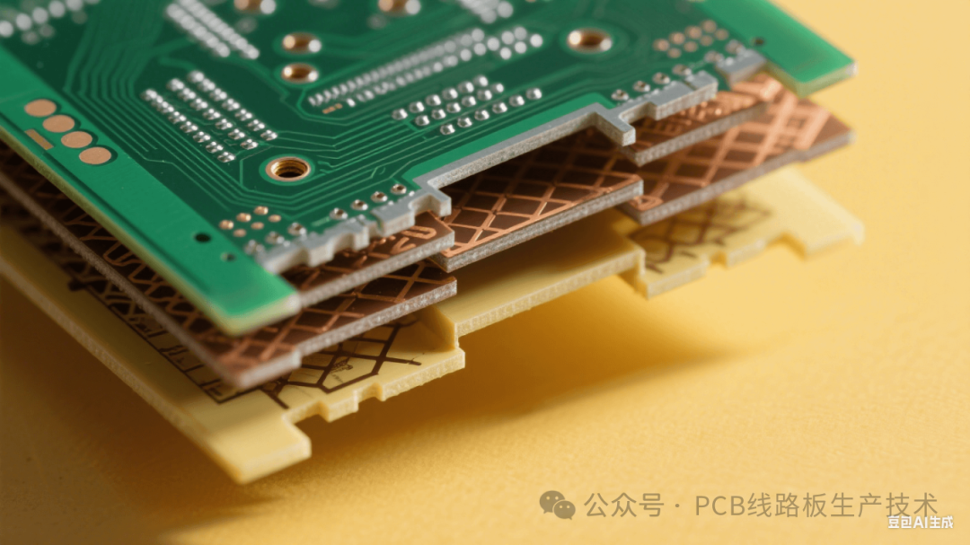
High-density interconnect (HDI) board selection is crucial for product miniaturization and functional integration. When designs require buried blind holes, micro-holes (<0.15mm), or stacked hole structures, it is essential to evaluate the board material’s resistance to CAF (conductive anodic filament) performance and drillability.
High Tg (glass transition temperature, above 170°C) materials such as Isola 370HR or Shengyi S1000-2M have stronger heat resistance and dimensional stability, capable of withstanding multiple pressing and reflow soldering impacts. Furthermore, HDI boards often use prepreg for interlayer filling, where the resin content (RC%) and flowability (Flow%) directly affect hole filling capability and interlayer thickness control, necessitating thorough communication with the board manufacturer regarding process capabilities during selection.
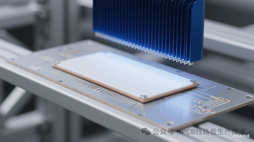
Thermal management capability is vital for power electronics and high-integration chip PCB selection. The thermal conductivity of the substrate is a key indicator. Ordinary FR-4 has a thermal conductivity of only 0.3W/mK, while metal substrates (such as aluminum substrates) can reach 1-3W/mK, and ceramic substrates (such as Al₂O₃, AlN) can reach as high as 20-200W/mK. For high-power LEDs, automotive controllers, or server motherboards, high thermal conductivity materials or designs with embedded copper blocks (Coin), and thick copper (such as 4oz or more) should be prioritized. Matching the thermal expansion coefficient (CTE) is also crucial—if ceramic chip carriers (Ceramic PGA/BGA) are installed on ordinary PCBs with significant CTE differences, enormous stress will occur during temperature cycling, leading to solder joint fatigue failure.
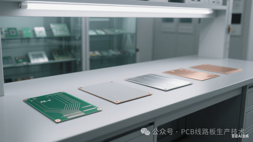
Cost and manufacturability (DFM) are practical constraints for selection. Pursuing high-performance materials will significantly increase costs. Engineers need to weigh:
Material grades: standard FR-4, medium Tg FR-4 (>150°C), high Tg FR-4 (>170°C), halogen-free FR-4, high-frequency / high-speed dedicated materials have significant price differences.
Layer count and structural complexity: increasing the number of layers and HDI structures (1 stages, 2 nd stages… any layer interconnection) will significantly increase manufacturing costs and cycles.
Surface treatment processes: HASL (hot air solder leveling), ENIG (electroless nickel immersion gold), OSP (organic solderability preservative), silver plating, tin plating, etc., vary in price and performance. ENIG is suitable for high-density BGA, but costs more than HASL; OSP is low-cost but has a short shelf life.
Special process requirements: gold finger hard gold plating, thick copper (>3oz), impedance control tolerances (such as ±5% vs ±10%) all affect pricing and delivery times. Early design collaboration with reliable board manufacturers (DFM Check) is crucial.
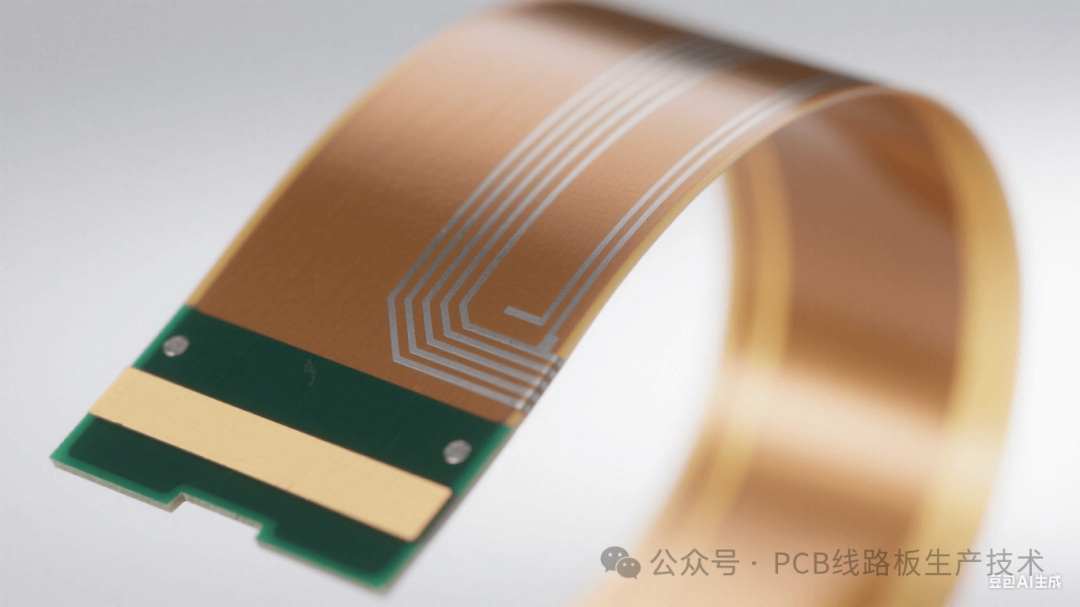
Rigid-flex boards provide unique value for three-dimensional wiring and are indispensable in wearable devices, aerospace camera modules, and medical endoscopes. Selection must focus on:
Flexible area materials: commonly used polyimide (PI) films (such as DuPont Kapton), need to evaluate their bendability (minimum bend radius), tear strength, and high-temperature stability.
Adhesive selection: acrylic (such as 3M™ ACM) and epoxy adhesives have their advantages and disadvantages in flexibility, heat resistance, and Z-axis expansion.
Rigid-flex transition zone design: stress concentration points need to be reinforced (such as windowing the cover layer, reinforcement plates) to avoid breakage due to repeated bending. Applications with high shielding requirements can form a flexible area shielding layer by covering copper on the PI film.
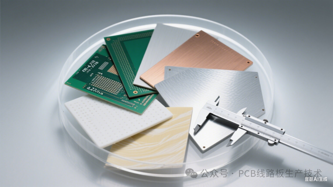
Environmental compliance and long-term reliability cannot be overlooked. Lead-free compatibility requires materials to withstand higher lead-free reflow solder peak temperatures (~260°C), and high Tg materials are fundamental. Automotive electronics (AEC-Q200 standards), industrial control, or outdoor equipment must use materials with excellent moisture resistance and CAF resistance (such as Isola FR408HR or Taiflex TU-768). For immersion processes or high-humidity applications, low moisture absorption materials (such as certain PTFE substrates with moisture absorption rates < 0.02%) should be prioritized.
Mastering this systematic PCB selection guide means establishing the optimal balance of performance, reliability, and cost from the outset of design. It requires engineers to traverse the boundaries of circuit design and materials science, seeking the golden intersection among electrical characteristics, mechanical strength, thermal management, manufacturability, and cost constraints. Continuous attention to the development of new materials and processes, along with close collaboration with PCB manufacturers, will make selection decisions more precise and efficient.
(IPCB)Aibi Circuit focuses on PCB manufacturing and technological innovation, providinghigh-speed material selection support,HDI process optimization solutions andcustom thermal management design full-process services. For automotive-grade AEC-Q200 certification, high-frequency millimeter-wave impedance control, and other core needs, our engineering team relies on mature process capabilities and simulation verification systems to ensure precise implementation of selection solutions. Contact Aibi Circuit now to empower your product’s competitiveness from design to mass production.
(For more professional content, please click “Read the original text” for further reading.)