[Download original PDF for free at the end of the article (journal paper format)]
Abstract:This article mainly introduces the ideas and processes of building an autonomous following logistics vehicle from three aspects: mechanical design, hardware selection, and drive control. It also details the problems encountered and their solutions during the process, providing a comprehensive reference for enthusiasts interested in this topic.
01


This series discusses my undergraduate thesis (over 7 years ago, quite historic~), where I created a logistics vehicle that can autonomously follow. Today, I am sharing the fun of the production process as a case study.
First, let’s look at some images.
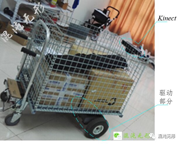
Figure 1.1 Physical Prototype of the Logistics Vehicle
As shown in Figure 1.1, the upper part is equipped with a Kinect, used for subsequent target recognition and autonomous tracking functions; below is the two-wheel differential drive part (rubber wheels), and in front are two smaller omnidirectional wheels. The advantages and disadvantages of this motion configuration are analyzed in detail in Chapter 4 of my article “Analysis of the Motion Model and Applications of Two-Wheel Differential Drive Robots“. Interested readers can refer to that.
The initial intention of creating this logistics vehicle came from seeing the autonomous following logistics vehicle from DHL online (Figure 1.2), which seemed very interesting. Staff can walk without pushing the logistics vehicle, as it “consciously” follows them, stopping and going, greatly freeing their hands and enhancing the fun of working with the logistics vehicle.

Figure 1.2 DHL Logistics Robot
Additionally, I saw an engineering dad online who directly transplanted the autonomous following function to a baby stroller, changing the mode from “pushing a stroller” to “stroller autonomously following,” allowing for hands-free outings with the baby and adding new fun to parenting.
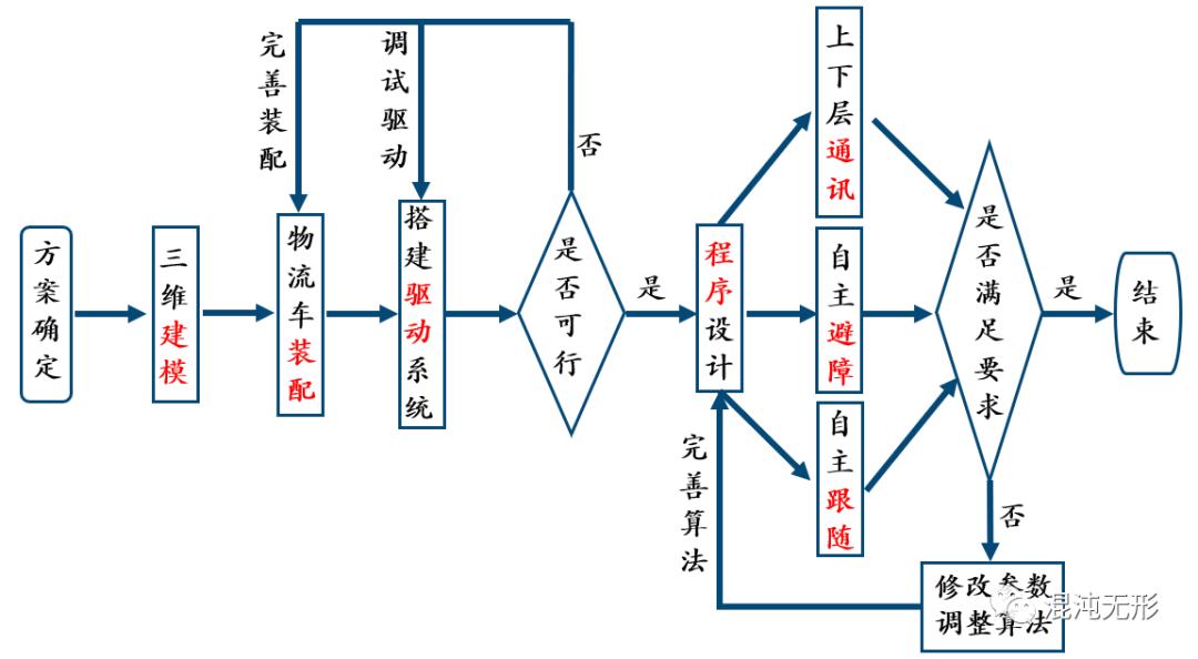
Figure 1.3 Design Flowchart
As shown in Figure 1.3, this article will detail the mechanical design, hardware selection, and the implementation of motion control for the vehicle (this article covers the first half, while the second half will be introduced in the next article).
02


The logistics vehicle has a strong load capacity, and considering functional requirements, production costs, and development cycle, I decided to modify a non-driven logistics vehicle into a two-wheel differential drive chassis. This way, only the rear drive part needs to be processed and manufactured, replacing the two original rear wheels of the chassis. This satisfies the basic functions of the logistics vehicle while reducing production costs and improving development efficiency.
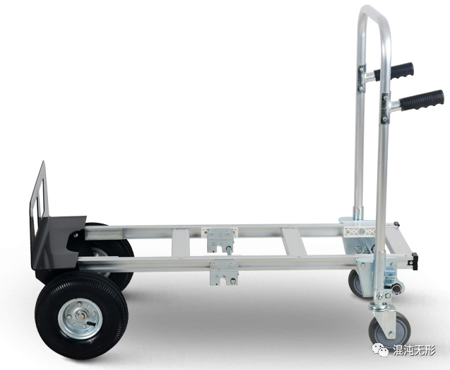
Figure 2.1 Hand-Pushed Logistics Vehicle
Therefore, I purchased a hand-pushed logistics vehicle with a load capacity of 300kg for modification, as shown in Figure 2.1.
The rear wheel part of the hand-pushed logistics vehicle was disassembled for modification, with the results shown below:
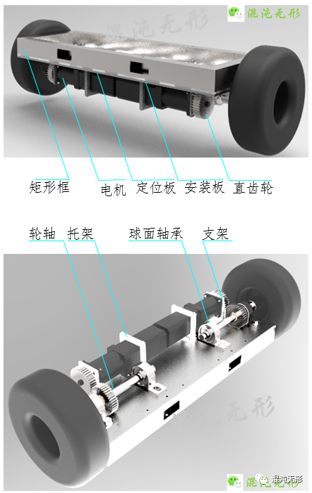
Figure 2.2 Drive Device
The processed components in Figure 2.2 are listed in the table below
Table 2-1 Processed Components
| Processed Component | Remarks |
|---|---|
| Wheel Axle | Φ20×250 |
| Rectangular Frame | 50×30 Rectangular Tube |
| Positioning Plate | 3mm Stainless Steel Plate |
| Mounting Plate | 5mm Stainless Steel Plate |
| Motor Mounting Bracket | 45 Steel |
| Motor Support | 45 Steel |
The standard parts used in Figure 2.2 are as follows
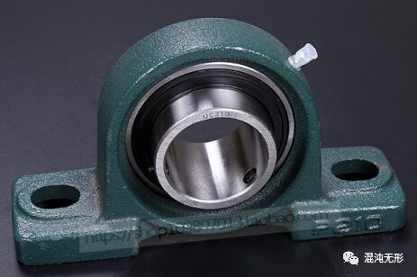
(a) UCP204 Mounted Spherical Bearing
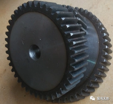
(b) Straight Gear
Figure 2.3 Standard Parts
Among them, the basic rated dynamic load Cr for UCP204 is 9.95kN, and the basic rated static load C0r is 2.65kN; the parameters for the straight gear are a module of 2 and 35 teeth, with an outer diameter of 74mm.
The motor parameters are shown in Table 2-2. This motor has a rated speed of 3000RPM and a minimum speed of 1RPM. Considering the torque size of the output shaft, a speed reducer with a ratio of 1:20 is installed at the front end of the motor to better suit the design specifications of this logistics vehicle. The motor uses a 2500-line encoder, which is particularly suitable for high-speed and low-noise applications.
Table 2-2 Servo Motor Parameters
| Power | Torque | Speed | Voltage | Reduction Ratio |
|---|---|---|---|---|
| 400W | 1.27NM | 3000RPM | 48V | 1:20 |
After assembling the above components, the drive part was installed in the original position of the hand-pushed vehicle, as shown in Figure 2.4.
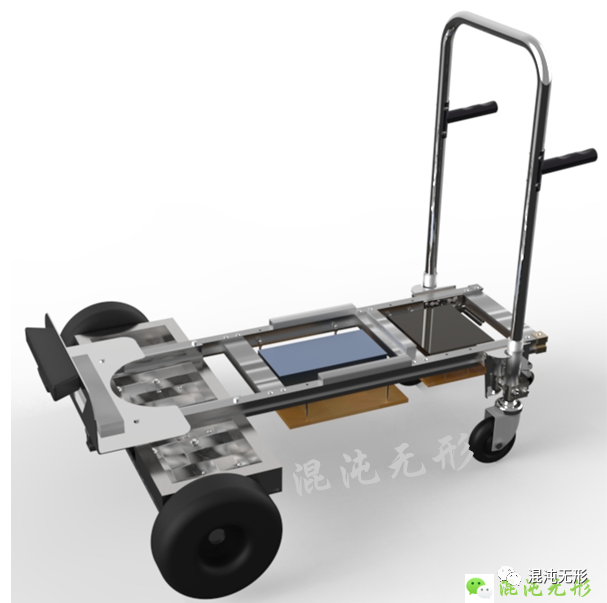
Figure 2.4 Effect of Modified Hand-Pushed Vehicle
03


Based on the mechanical body, I built the control circuit, transmitting data collected from various sensors to the industrial computer for processing, achieving intelligent functions for the logistics vehicle.
Considering the above, the hardware is mainly divided into four parts: controller, motor and drive, visual sensors, and ultrasonic sensors.
3.1
The controller is the core processor of the electrical system, required to execute multiple complex tasks. Hierarchically, the upper-level industrial computer mainly runs ROS (Robot Operating System), collects depth camera data for image processing, receives data sent from the lower machine, and sends data to the lower machine.
Considering the performance, size, price, and other factors of the upper computer, I ultimately chose an industrial computer, as shown in Figure 3.1, with an I7-4500U processor, a main frequency of 2.0GHz, 4G memory, and a 64G solid-state drive, with a power supply of 60W.
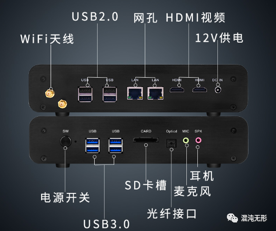
Figure 3.1 Industrial Computer Image
The lower-level microcontroller is mainly used for motor control, encoder data collection, and ultrasonic data collection, performing simple processing and communicating with the upper computer.
Considering that the selected encoder has 2500 lines and the reducer has a reduction ratio of 1:20, the microcontroller uses an interrupt-triggered method to read encoder data. The program adopts a 4x frequency reading method, so when the wheel rotates once, the encoder reading is 200,000, meaning that one complete rotation of the wheel will produce 200,000 interrupts. When both motors rotate once, the total interrupts will reach 400,000, thus requiring high performance from the microcontroller for collecting encoder data and controlling the motor. Considering development cycle, performance, price, and other factors, I chose the Arduino DUE microcontroller, as shown in Figure 3.2. The Arduino Due is based on a 32-bit ARM processor with an 84 MHz clock frequency, making it suitable for motor control.
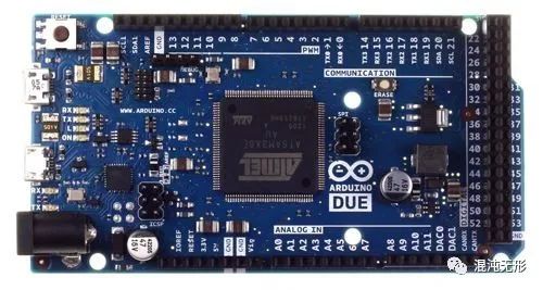
Figure 3.2 Arduino DUE
The ultrasonic module also requires a microcontroller for data collection. Since there are three ultrasonic modules, and collecting data requires delays, combining three ultrasonic modules results in excessive delays, making it unsuitable for processing on the Arduino DUE microcontroller to avoid affecting PID calculations. Therefore, I selected another Arduino Mega2560 microcontroller, as shown in Figure 3-4, to serve as a separate node for collecting ultrasonic data, processing it, and uploading it to the upper computer. The Arduino Mega2560 has six external interrupts, which can be used to handle the ultrasonic modules, thus bypassing the waiting time for receiving signals and improving data processing speed.
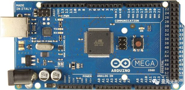
Figure 3.3 Arduino Mega2560
In summary, the Arduino DUE microcontroller is used for collecting encoder data and controlling the motor, while the Arduino Mega2560 microcontroller is used for collecting ultrasonic data and performing filtering. The two microcontrollers communicate with the industrial computer to achieve data processing and transmission.
As previously mentioned, the motor selected is the YZ-ACSD608 AC servo motor, paired with the ACSD608 low-voltage AC servo motor driver.
The wiring diagram for connecting the Arduino DUE microcontroller to the driver is shown below.
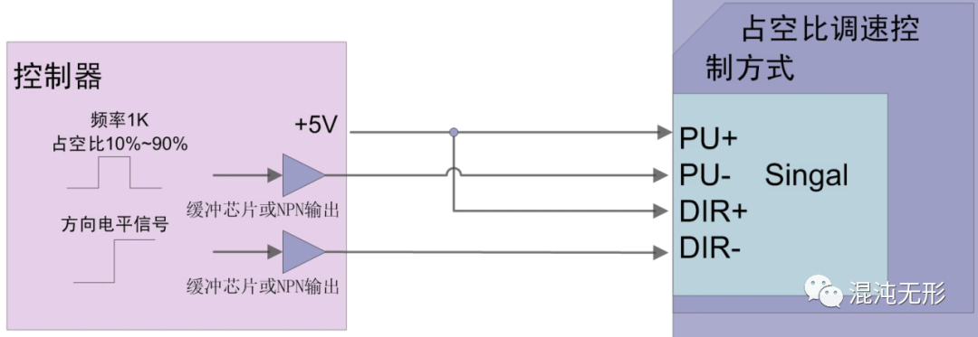
Figure 3.4 Wiring Diagram for Driver Control Signal
Connecting to the corresponding pins of the Arduino DUE microcontroller, the pin connections and their labels are listed in Table 3-1.
Table 3-1 Motor-Microcontroller Wiring Table
| Driver Interface | DUE Pin (Left Motor) | DUE Pin (Right Motor) |
|---|---|---|
| PU+ | 4 | 7 |
| PU- | 35 | 37 |
| DIR+ | 4 | 7 |
| DIR- | 8 | 11 |
| EN+ | 3.3V | 3.3V |
| EN- | 4 | 7 |
Where PU— is used for PWM output, and the output voltage U= (PU+) – (PU-)
DIR-— is used for direction control
EN-— is for enable control, where EN- = HIGH allows the motor to rotate
After completing the required wiring for the driver, PID speed regulation is necessary, requiring the reading of encoder values. The wiring table for the encoder and Arduino DUE microcontroller is shown in Table 3-2.
Table 3-2 Encoder-Microcontroller Wiring Table
| Encoder Pin | DUE Pin (Left Encoder) | DUE Pin (Right Encoder) |
|---|---|---|
| GND | GND | GND |
| A | 2 | 3 |
| B | 5 | 8 |
Interlude
During the testing phase, I found that the ultrasonic sensor readings were greatly interfered with. One phenomenon was:
When the Mega2560 microcontroller collecting ultrasonic data and the DUE microcontroller controlling the drive were both connected to the USB port of the industrial computer, the ultrasonic data was very jittery. However, after disconnecting the DUE microcontroller, the data displayed normally.
Therefore, it can be determined that the DUE microcontroller affects the ultrasonic data reading. Comparing the unconnected DUE microcontroller plugged into the industrial computer does not affect the ultrasonic data reading, thus further confirming that the driver module connected via Dupont wires to the DUE microcontroller interfered with the Mega2560 microcontroller’s ability to read and send ultrasonic data.
Furthermore, by unplugging the signal lines of the DUE microcontroller, I found that the root cause was the three lines of the encoder, namely the A phase line, B phase line, and GND line, which all affected the ultrasonic data reading. Since the encoder output is 5V, while the DUE microcontroller operates at 3.3V, using the DUE microcontroller to control the motor works fine, but when integrating data from other sensors, there may be mutual interference.
Therefore, I used a high-speed optical isolation module to isolate the encoder and the DUE microcontroller. With two encoders, a total of four signal lines and one ground line are used, hence a 4-channel opto-isolation module was used, as shown in Figure 3.5, with a common cathode signal input. Ultimately, the encoder and Arduino DUE microcontroller were isolated, allowing normal reading of ultrasonic data.
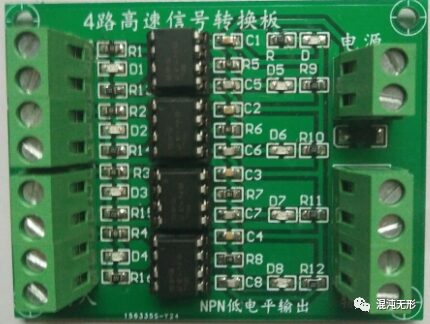
Figure 3.5 4-Channel High-Speed Optical Isolation Module
As shown in Figure 3.6, the Kinect features both depth and RGB cameras, capable of simultaneously acquiring RGBD information (back then, there were not many RGBD cameras available, and it could also recognize human skeletal points, which was a very cool technology at the time, so I had to play with it). Therefore, I chose to use the Kinect as the visual sensor to achieve the autonomous following function for the logistics vehicle.
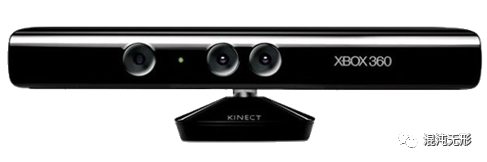
Figure 3.6 Kinect V1
To achieve the autonomous obstacle avoidance function of the logistics vehicle, I considered using ultrasonic sensors to measure the distance between the vehicle and obstacles, selecting the US-100 (which has a built-in temperature sensor) that can automatically calibrate the measurement results, as shown in Figure 3.7.
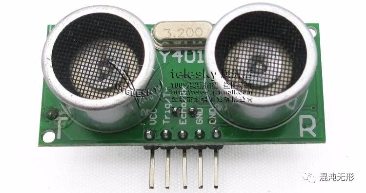
Figure 3.7 US-100 Ultrasonic Sensor
04


After completing the mechanical design and hardware selection, I began to build the robot’s drive system and control its movement.
As shown in Figure 4.1, the circuit design block diagram indicates that the battery supplies power to the industrial computer, drive, and Kinect, while the two microcontrollers are powered by the industrial computer through USB, and the ultrasonic sensor is powered by the Arduino Mega2560. The Arduino Mega2560 serves as a node for collecting ultrasonic data, while the Arduino DUE serves as another node for controlling the motor and collecting encoder data. The Kinect collects image information, and all data is fused and processed in the industrial computer.
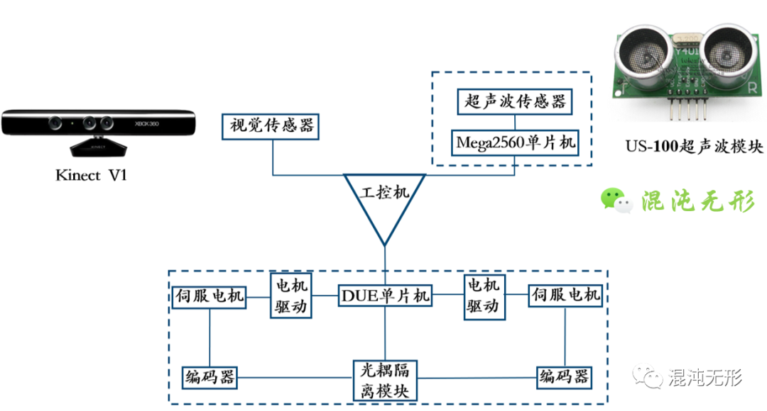
Figure 4.1 Circuit Design Block Diagram
Following the schematic in Figure 4.1, I connected these scattered hardware components, resulting in the overall effect shown in the following image, which appears somewhat messy.
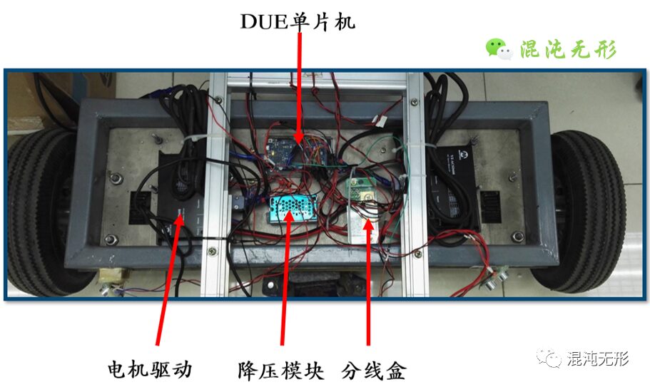
Figure 4.2 Actual Wiring of the Drive System
After building the drive system, I needed to write a program to drive the motor and make the vehicle move. (This is a big pit: the author plans to write a series of articles on motor control later, detailing various motor control algorithms and implementation solutions, so this article will only briefly cover the implementation aspect.)
4.2.1 Driving the Motor
The PWM (Pulse Width Modulation) duty cycle is approximately proportional to the output voltage, which in turn determines the speed of the motor (the higher the voltage, the faster the motor). Therefore, the motor speed can be adjusted by outputting PWM from the microcontroller to regulate the duty cycle.
The motor is controlled using the Arduino DUE, which comes with many library functions; for instance, the analogWrite() function can directly control the output frequency of the pin at 490Hz. However, when applied to the logistics vehicle, a buzzing phenomenon occurred at low motor speeds, which was determined to be caused by the low PWM output frequency. Thus, it was necessary to increase the PWM wave frequency to improve the motor’s working state.
I found a library on GitHub for modifying the output PWM frequency of the Arduino DUE, setting the PWM frequency to 10KHz, which eliminated the buzzing phenomenon.
4.2.2 Encoder Data Collection
To accurately and timely grasp the motor’s operating conditions, it is necessary to constantly read the encoder values. The encoder emits a pulse signal every time it rotates a certain angle, and this pulse signal triggers an external interrupt on the microcontroller’s pin, allowing for counting.
Typically, encoders have A and B phases, with A and B outputting pulses that are delayed by 1/4 cycle relative to each other, allowing for the distinction between forward and reverse motor rotation. The timing diagram is shown in Figure 4.3.
The microcontroller’s timer is configured to periodically collect the number of pulse signals, thus calculating the motor’s speed.
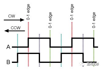
Figure 4.3 Timing Diagram of Encoder A and B Phases
4.2.3 Closed-Loop Control
To precisely control the motor speed, a closed-loop control system is employed, where the difference between the actual motor speed and the theoretical speed is input to the PID controller for computation, and the calculated result is output through PWM to ensure that the theoretical speed sent matches the actual rotation speed of the motor.
When the wheel encounters an obstacle and gets stuck, the PID will automatically increase the PWM output value to boost the motor’s output power, allowing it to overcome the obstacle.
The operational states of the two driving wheels of the logistics vehicle may differ slightly; therefore, it is necessary to adjust the PID parameters separately for the left and right wheels.
Through the above three steps, precise control of the motor speed is achieved, laying the foundation for the subsequent development of the autonomous following function. (The autonomous following function will be elaborated in the next issue~)
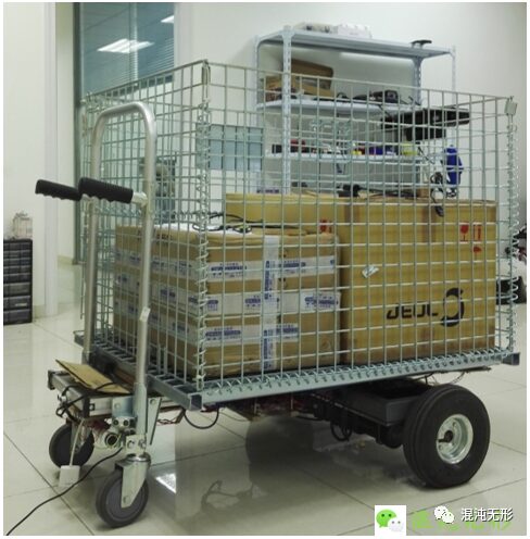
Figure 4.4 Physical Prototype Display
05


This article mainly elaborates on the mechanical design, manufacturing, and assembly plans and processes for the autonomous following logistics vehicle. Based on the mechanical body, appropriate processors, sensors, and other hardware were selected, and the hardware circuit was built. Finally, the PID control scheme for the motor was discussed, achieving precise control of the motor speed and laying the groundwork for the subsequent development of the autonomous following function.
(The article is solely the author’s personal analysis; please correct any errors. Thank you!)
I have organized the original PDF of the journal paper format for everyone, making it convenient for collection and reminiscence
To obtain it, share this article in your circle of friends and gather 10 likes. Take a screenshot and send it to the backend or email: [email protected]. After review, a download link will be sent in response.
Note: The original PDF effect can refer to the previous article’s download link at the end (August 21, 2022), such as
Analysis of the Motion Model and Applications of Car-like Robots
Further Reading
Analysis of the Motion Model and Applications of Two-Wheel Differential Drive Robots
Research on Integrated Perception and Planning Systems for Automotive Robots (M11)
Overview of Robot System Design and Development
Analysis of Wheel Mobile Robot Odometry
Summary of Current Research Status of Robot Motion Planning Algorithms
Summary of Current Research Status of Robot Spatial Sampling Algorithms
Summary of Current Research Status of Robot Graph Planning Algorithms
Summary of Current Research Status of Robot Environmental Perception
Summary of Common Kinematic Models of Mobile Robots
Comparative Analysis of Common Mobile Robots from Multiple Angles
Calibration of Wheel Spacing for Differential Drive Robots
Calibration of Wheel Diameter for Common Mobile Robots
—————————————————————————–
Related Statements
1. If you reprint this article, please be sure to indicate at the end: “Reprinted from WeChat Public Account: Chaotic and Invisible”
2. If there is any infringement, please contact the author

End of the text, thank you for reading! If you find it well written, please give it a like or “see it”.
Chaotic Small Shop is now open, welcome to visit: Chaotic Small Shop
Chaotic Small Kitchen has started cooking, welcome to visit: Chaotic Small Kitchen