
Abstract: The processing of small diameter internal grooves is very common in machining, while traditional processing methods often lead to low processing efficiency, dimensional deviations in the groove diameter, and substandard surface roughness, resulting in a low product qualification rate. This article studies a processing method based on CNC lathes, which has been verified through practice to produce products with stable quality, significantly improved processing efficiency, and a qualification rate of 99.7%.
Small diameter internal groove parts are widely used in military and civilian aircraft, mainly for sealing nuts, sleeves, and bushings among other products. The demand for this type of part is large, but traditional processing methods result in poor quality stability and low qualification rates, posing safety risks for users. The low qualification rate also increases product costs, making it unacceptable for users. However, with the continuous development of CNC technology, a good foundation has been provided to solve this problem. This article takes the processing of a hydraulic pipeline blocking bolt for an aircraft as a typical case of processing small diameter internal groove parts. It analyzes the traditional processing methods and their shortcomings, and provides processing procedures, tool selection, and cutting parameters based on the Kia SKT15z multifunctional CNC lathe.
1. Traditional Blocking Bolt Processing Process and Analysis
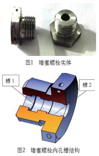
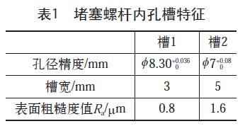
A blocking bolt is primarily used in the hydraulic pipelines of aircraft, mainly serving to seal the flow through the pipeline, thus requiring high sealing performance. Consequently, the quality requirements for the internal surface roughness of the internal hole and groove are also high. Its structure is shown in Figure 1. The characteristics of the small diameter internal groove (see Figures 2 and Table 1) are: the internal hole diameter is φ 6H7, and it contains two groove cavities (groove 1 and groove 2), with dimensions of hole diameter φ 8.30+0.0360 mm, groove width 3 mm and hole diameter φ 7+0.080 mm, groove width 5 mm. The surface roughness value of groove 1 is Ra=0.8μm, and that of groove 2 is Ra=1.6μm.
(1) Traditional Processing Workflow. The traditional processing equipment for small diameter internal grooves mainly uses CNC single-board machines, and the tools used are white steel forming R tools for rough and finish machining of the internal grooves. The processing steps are: ① Rough turning the outer diameter φ 17mm and making a hole φ 5mm, then re-facing the end surface and boring to φ 5.9mm, followed by processing the internal groove 1 hole φ 8.30+0.0360 mm, then re-facing the end surface to turn the outer diameter φ 14mm and R1mm, cutting the thread M16×1.5-6g, and finally processing the groove 2 hole φ 7+0.080 mm, and lastly reaming φ 6H7. In actual processing, the steps are complicated, resulting in a relatively high defect rate.
The specific processing steps are as follows.
10 turning: Rough turning the outer diameter φ 17mm, making a hole φ 5mm.
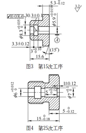
15 turning: Re-face the end surface, bore to φ 5.9mm, and process the internal groove hole φ 8.30+0.0360 mm, width 3mm, R0.3mm, ensuring roundness tolerance requirements, as shown in Figure 3.
20 turning: Re-face the end surface, ensuring the total length dimension of 150-0.18mm, turn the outer diameter φ 14mm, and R1mm, and cut the thread M16×1.5-6g.
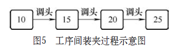
25 turning: Using the thread for positioning, process the internal groove hole φ 7+0.10 mm and groove width 5mm, as shown in Figure 4.
Finally, ream φ 6H7 to complete processing.
(2) Analysis of Traditional Processing Technology. Traditional processing equipment typically uses CNC single-board machines, which have fewer tool positions and require multiple setups during processing, resulting in low efficiency; the tools used for processing internal grooves have long tool holders that must extend more than 12.3mm, with a single-side cutting depth of 1.15mm, and the root of the groove has two R (0.3±0.1) mm, which creates significant cutting resistance and generates a lot of cutting heat, leading to rapid tool wear; simultaneously, due to the small internal diameter of φ 6mm, the processing space is limited, making chip removal difficult, and chips tend to remain in the internal groove, which not only scratches the hole wall but also easily breaks the internal groove tool holder. Therefore, the traditional process flow is characterized by low processing efficiency and unstable processing quality, which are key issues that this article’s new processing method aims to address.
Low processing efficiency: The internal hole and outer diameter dimensions require multiple setups to complete, each process needing to be re-positioned, leading to long processing times, low efficiency, and potential for processing errors due to frequent setups, as shown in Figure 5. Unstable processing quality: The dimensions of the internal groove wall are relatively complex, with high requirements for dimensional and positional tolerances. Due to the processing of the internal groove φ 8.3mm in a small hole of φ 6mm, along with tool wear and vibration, this results in dimensional deviations of φ 8.30+0.0360 mm and an internal groove wall surface roughness value Ra=0.8μm that does not meet requirements, leading to a qualification rate of only 80%.
2. CNC Processing Technology Analysis
(1) Selection of Processing Equipment. Based on the processing requirements of this part, the Kia SKT15z multifunctional CNC lathe was chosen to complete the processing in two steps. The advantages of using a multifunctional CNC lathe include: ① Good rigidity, high precision, and stability of the machine tool, ensuring the precision requirements of the product processing. ② Multiple processes can be completed with a single setup; the CNC lathe has a total of 12 tool positions to sequentially complete turning the outer diameter, retreating the groove, cutting the external thread, drilling, boring, and rough and finish machining of the internal groove. ③ Good cooling and lubrication effects, which reduce the cutting heat generated during processing. ④ High production efficiency, shortening the processing time of the product and reducing the labor intensity of workers.
(2) Processing Workflow. By analyzing the capabilities of the CNC equipment, the original 4-step process was optimized to 2 steps. The optimized steps are as follows.
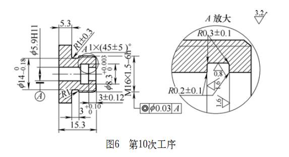
10 turning: Rough turning the outer diameter and cutting the thread M16×1.5-6h, making a hole φ 5.9H11, and processing the internal groove φ 8.30+0.0360 mm, ensuring R (0.3±0.1) mm and R (0.2±0.1) chamfers, as shown in Figure 6.
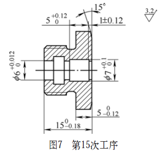
15 turning: Re-face the end surface and cut a 15° chamfer, bore to φ 6+0.0120 mm, and process the internal groove hole φ 7+0.10 mm, width 5mm, as shown in Figure 7. Finally, ream φ 6H7 to complete processing.
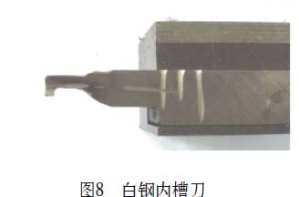
(3) Tool Selection for Processing. Rough processing tools: The focus of processing the part is on the internal hole and internal groove processing and chip removal issues. The selection of rough processing tools considers the following aspects: ① Tool material selection, using white steel as the rough processing tool, which is made of high-speed steel, providing excellent cutting performance with good toughness and hardness. ② Tool geometry, the white steel tool has a cutting width of 2.0mm to reduce radial cutting force, with a front angle of 10°–15°, a side angle of 1°–2°, and the cutting edge must be horizontal and not higher than the workpiece center line, with the back face ground into a rounded arc to ensure no interference with the groove bottom, as shown in Figure 8. ③ Tool rigidity, the length of the tool holder extension depends on the workpiece requirements; the shorter the extension, the better the rigidity; conversely, the longer the extension, the worse the rigidity. Therefore, the ideal length for the tool holder is determined based on the processing depth L=6mm, so the tool length is chosen to be L=7mm (greater than 6mm), ensuring good rigidity and cutting performance for the internal groove tool.
Precision processing tool selection: An integral carbide grooving tool is used as the finishing tool for processing the internal groove, as shown in Figure 9.
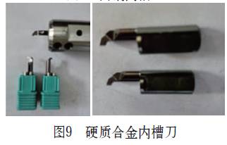
The characteristics of carbide tools: Tool material. Carbide has high hardness, strength, and wear resistance, especially its high hardness and wear resistance, maintaining good cutting performance at high temperatures. Geometry. The length of the tool head extension is 10mm, with a cutting edge width of 1.0mm, a front angle of about 3°–5°, and the corners of the tool width are R0.1mm, with sharp cutting edges, low cutting resistance, and good cutting performance, fully meeting the dimensional tolerance requirements for processing the internal grooves. Tool holder design. The tool head is designed to be embedded, allowing for quick installation on the tool holder, with high repeat positioning accuracy, high precision, good interchangeability, ease of use, and quick replacement.
(4) Determination of Processing Parameters. Rough processing of internal grooves and programs. The steps for processing the internal hole are: ① Center drilling to avoid runout. ② Drill φ 5.5mm, then enlarge to φ 5.8mm. ③ Bore to φ5.95mm, mainly to minimize the cutting allowance during internal hole processing, ensuring uniform force on the internal groove tool.
During rough turning of the internal groove, the spindle speed is set to 900r/min, feed rate to 0.03mm/s, and a cutting depth of a p=0.4mm is chosen for processing, utilizing interrupted cutting to process each pass using the grooving cycle command G75, ensuring that the chips produced are short and arc-shaped rather than long and rolled, allowing for sufficient space for chip removal without clogging the internal groove tool; simultaneously providing adequate cooling for the tool using CNC machine-specific cutting fluid, primarily to cool the tip and effectively remove processing chips. After the first cut, the program is paused using command M00 to promptly remove any accumulated chips at the bottom of the small holes and grooves before proceeding with the second cut, ensuring timely removal of chips from the internal groove to prevent pressure on the cutting edge and prolong tool life. The programming is as follows:
T0808;
M3 S900; (Spindle forward, speed 900r/min)
M08; (Cutting fluid on)
G00 X5.8 Z1;
Z-5.8; (Rapid positioning to 5.8mm, leaving 0.2mm allowance on the left end)
G75 R0.2:
G75 X8.10 P200 F0.03; (Grooving cycle command G75)
G01 Z2 F0.1; (Exit workpiece)
G00 X100 Z100 M9;
M00; (Program pause, remove accumulated chips from internal groove)
M3 S900;
G00 X5.8 Z1 M8; (Rapid positioning to outside of hole)
Z-5.0; (Leave 0.2mm allowance on the right end of the second cut)
G75 R0.2;
G75 X8.10 P200 F0.03; (Grooving cycle command)
G01 Z10 F0.1; (Exit workpiece)
G00 X100 Z100;
M5;
…
Precision processing of internal grooves and programs. Due to the selection of solid carbide material for the tool, with a cutting edge width of 1mm, and based on its high hardness and wear resistance, a higher spindle speed n=1,800r/min and a low feed speed f=0.02mm/r are chosen for precision turning. Since the processing allowance is small, only about 0.2mm, it can meet the requirements for internal groove φ 8.30+0.0360 mm, R0.3mm, R0.2mm, and surface roughness.
The specific programming is as follows:
T1010;
M3 S1800; (Spindle forward, speed 1,800r/min)
G00 X5.7 Z1 M08;
G01 Z-6 F0.15; (Positioning to processing groove depth L=6mm)
W-0.3;
G01 X6 F0.05;
G03 X6.6 W0.3 R0.3; (Circular interpolation command for R0.2mm)
G01 X8.3 R0.3 F0.02; (Internal groove 1 bottom diameter size and R0.3mm)
Z-5.5;
G00 X5.7;
Z-3.0;
W-1;
W0.3;
G01 X6 F0.05;
G02 X6.6 W-0.3 R0.3; (Circular interpolation command for R0.2mm)
G1 X8.33 R0.3 F0.02; (Right groove end face bottom diameter size and R0.3mm)
Z-6.01 R0.2;
X5.7; (Return to φ 5.7mm)
G01 Z20 F0.2; (Exit workpiece)
G00 X100 Z100;
M09;
M05; (Stop spindle)
…
Finally, process the dimensions of internal groove 2, with the processing steps including cutting the internal thread core shaft M16×1.5, positioning the end face with the thread, ensuring the total length dimension and cutting a 15° angle, then similarly using the G75 command for rough processing the internal groove φ 7mm, leaving a 0.1mm allowance at the groove bottom, and then finish turning the internal groove φ 7+0.10 mm, ensuring the dimensions of groove 2 and related dimensions meet requirements.
3. Actual Effects of CNC Processing
To illustrate the rationality, feasibility, and effectiveness of this data processing technology, a batch of parts was simultaneously processed using the new and traditional methods at a certain machining center to verify the actual processing effects.
The results show that the new method increases processing efficiency by 57.1%, reduces the number of processing steps by 50%, and improves the product qualification rate to 99.5%. Detailed information is shown in Table 2.
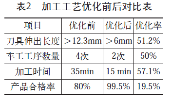
Project optimization before and after optimization rate: Tool extension length >12.3mm >6mm 51.2% Number of turning steps 4 times 2 times 50% Processing time 35min 15min 57.1% Product qualification rate 80% 99.5% 19.5% The product processing quality of the groove-type blocking bolts has been significantly improved, with the qualification rate increasing to 99.5%, and processing time greatly reduced, which not only lowers the labor intensity of workers but also improves work efficiency. At the same time, this method is an initial exploration of the processing technology for small diameter internal groove parts on multifunctional CNC lathes and can serve as a reference for processing various sleeve-type small diameter internal grooves, multi-step internal grooves, and multi-groove internal grooves.
4. Conclusion
The traditional processing methods for small diameter internal grooves have low efficiency, dimensional deviations, and high labor intensity, resulting in low product qualification rates. This article explores the processing methods for this type of part based on CNC machine tools, demonstrating through actual processing results that using CNC equipment, selecting appropriate tools, optimizing processing steps, setting suitable processing parameters, and CNC programs can significantly improve the product processing quality of small diameter internal groove blocking bolts, increasing the qualification rate to 99.5%, greatly reducing processing time, lowering labor intensity, and improving work efficiency. Furthermore, this method represents an initial exploration of processing technology for small diameter internal groove parts on multifunctional CNC lathes and can serve as a reference for processing various sleeve-type small diameter internal grooves, multi-step internal grooves, and multi-groove internal grooves.
References:
[1] Anonymous. Turning Technology [M]. Beijing: National Defense Industry Press, 1980.
[2] Liu Lijian, Miu Shengyong, Xu Yonggang, et al. CNC Processing Programming and Operation [M]. Beijing: Tsinghua University Press, 2007.
[3] Guo Peiling. Processing and Measurement of Small Diameter, Multi-step, and Multi-groove Hydraulic Cylinder Bodies [J]. Modern Manufacturing Engineering, 2002 (4): 36-37.
(This article was published in “Metal Processing (Cold Processing)” 2017, Issue 1 and 2. Author’s unit: Aviation Industry Corporation of China Hongdu Aviation Industry Group Co., Ltd.)
In 2017, the “Tool” column of Metal Processing (Cold Processing) magazine calls for papers as follows:
(1) Advanced technology and development trends of tools. (2) Advanced design concepts and manufacturing experience of tools. (3) Tool selection and application. (4) Insights on using tools in actual processing. (5) Specific case analysis or improvement solutions for tool usage.
The articles submitted for this call for papers in the “Tool” column focus on the category of metal processing and cold processing. Once accepted, they will be published immediately! Official submission website: http://tougao.mw1950.cn, click the link, log in to the website, register an account, and follow the steps to submit. We hope that many authors and readers will actively submit! No fees are required for submission!
Editorial Department of Metal Processing (Cold Processing)
Related Reading: Do you know how CNC blades are born, which are used every day?
Disclaimer: This article is a network reprint, and the copyright belongs to the original author. However, due to numerous reprints, it may not be possible to confirm the true original author, so only the source of reprint is indicated. If there are copyright issues, please contact us, and we will negotiate copyright issues or delete content in a timely manner! The content reflects the author’s personal views and does not represent the views of this public account or assume responsibility for its authenticity.
Machine Tool Tool World
Dedicated to guiding frontline technical staff in the manufacturing industry
To reasonably select CNC tools
Introducing the latest technological developments in the tool industry
Recommending the latest CNC tool products
Creating value for the manufacturing industry
WeChat: MW1950CT Submission: [email protected]
Produced by “Metal Processing”
“Machine Tool Tool World Base Camp” Groups 1 and 2 are full
Group 3 has been established
New friends and old friends quickly come to scan the code
Here you will find
More intense technical discussions
More direct process exchanges
More practical experience sharing
Please press and hold the following QR code to add the editor as a friend. After telling the editor your industry or field, you will be invited to join the group.

Purely technical exchange, please do not add friends for advertising or other information!
Popular Book Rankings
☞ Books Loved by Gold Powder
☞ General Mechanical Book Rankings
☞ Automotive Book Rankings