
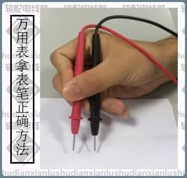
Click on the image to enlarge
1. Introduction to Multimeter
1.1 Definition
A multimeter is a magnetic electrical instrument equipped with a rectifier that can measure various electrical parameters such as AC and DC current, voltage, and resistance. For each electrical quantity, there are generally several ranges. Also known as a multi-purpose meter or simply a multimeter. The multimeter consists of a magnetic electric ammeter (the meter head), measurement circuit, and selection switch, among others. By changing the selection switch, it is easy to measure various electrical parameters. The main basis for circuit calculations is Ohm’s law for closed circuits. There are many types of multimeters, and one should choose according to different requirements.
Generally, a multimeter can measure DC current, DC voltage, AC voltage, and resistance. Some multimeters can also measure capacitance, inductance, power, and the common-emitter DC amplification factor hFE of transistors.
▲ Multimeter
1.2 Basic Functions
The multimeter can not only measure the resistance of the object being measured and AC/DC voltage but can also measure DC voltage. Some multimeters can even measure the main parameters of transistors and the capacitance of capacitors, etc. Mastering the usage of a multimeter proficiently is one of the fundamental skills in electronic technology. Common types of multimeters include analog multimeters and digital multimeters. An analog multimeter is a multifunctional measuring instrument centered around a meter head, with the measurement values indicated by the pointer on the meter head. A digital multimeter displays measurement values directly in numerical form on an LCD screen, making it easy to read, and some even come with voice prompts. A multimeter integrates a voltmeter, ammeter, and ohmmeter into one instrument.
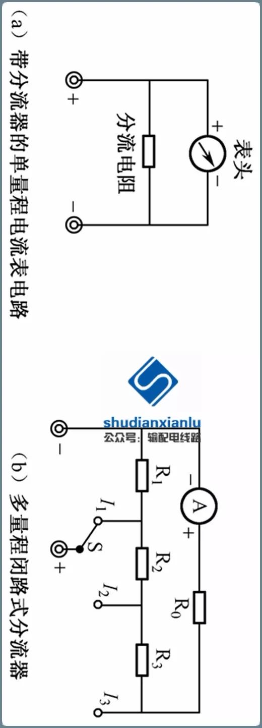
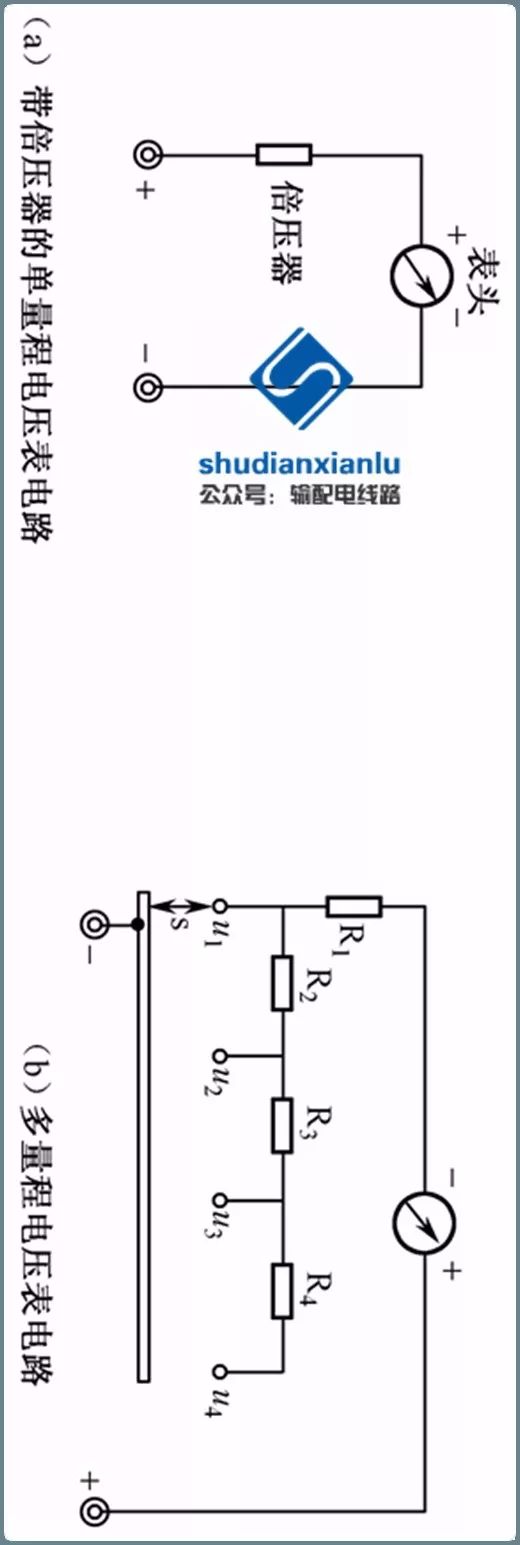
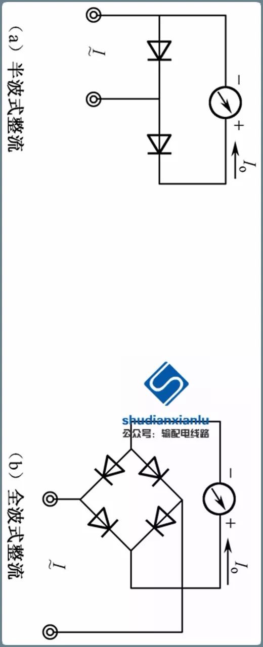
The DC current range of a multimeter is a multi-range DC voltmeter. The meter head can be connected in parallel with a closed circuit voltage divider to expand its voltage range. The DC voltage range of a multimeter is a multi-range DC voltmeter. The meter head can be connected in series with a voltage divider to expand its voltage range. Different voltage dividers correspond to different ranges. The meter head of the multimeter is a magnetic electric measurement mechanism, which can only measure DC by converting AC to DC using a diode, thus enabling the measurement of AC.
1.3 Classification
According to its internal structure, commonly used multimeters are classified into analog and digital types. An analog multimeter is a multifunctional measuring instrument based on a mechanical meter head, with measured values indicated by the pointer on the meter head; a digital multimeter displays measured values directly in numerical form on an LCD screen and often includes voice prompt functions.
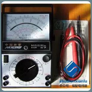
▲ Analog Multimeter
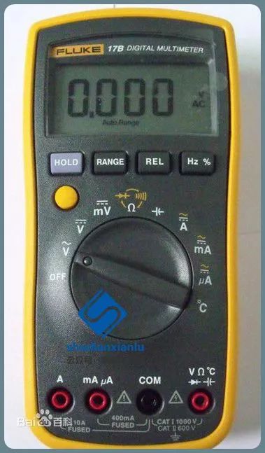
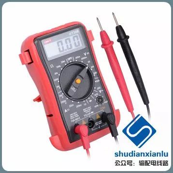
▲ Digital Multimeter
According to form factor, there are bench, clamp, handheld, and pocket types.
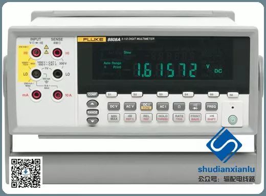
▲ Bench Multimeter
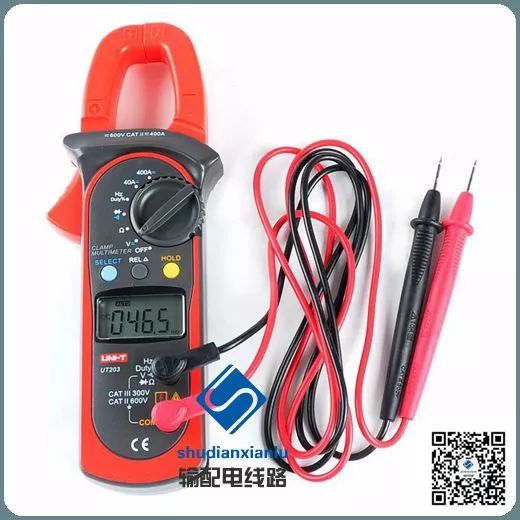
▲ Clamp Multimeter
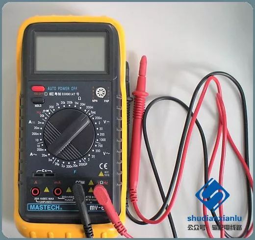
▲ Handheld Multimeter

▲ Pocket Multimeter
2. Usage of Analog Multimeter
2.1 Overview
An analog multimeter is a multifunctional, multi-range measuring instrument that can measure DC current, DC voltage, AC current, AC voltage, resistance, and audio levels. Some can also measure AC current, capacitance, inductance, and parameters of semiconductors (such as β).
The reading accuracy of an analog multimeter is slightly lower than that of a digital multimeter, but the movement of the pointer is more intuitive and obvious, and its speed and amplitude can objectively reflect the magnitude and direction of the measured value.
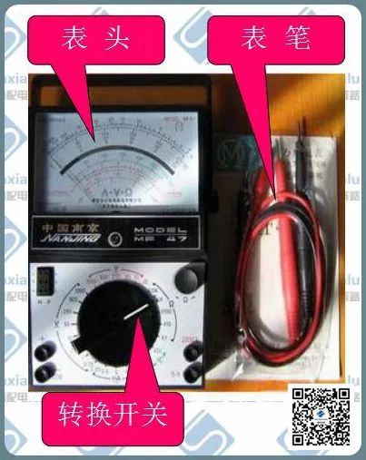
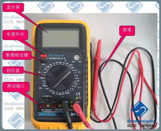
▲ Components of Analog Multimeter
Common models include MF30, MF47, MF50, MF500, etc. Today, we will primarily analyze and introduce the MF47 model.
2.2 Structure
The analog multimeter consists of three parts: indicating part (meter head), measurement circuit, and conversion device.
The indicating part (meter head) usually consists of a magnetic electric microammeter (some are milliammeter).
▲ Analog Meter Head
The main function of the measurement circuit is to convert the measured electrical quantity into a quantity suitable for indication on the meter head.
The conversion device usually consists of a selection (conversion) switch, terminals, buttons, and jacks.
▲ Analog Conversion Switch
2.3 Characteristics
1) One of the important performances of a multimeter is sensitivity, which refers to the current value through the moving coil when the pointer of the meter head deflects from the zero scale to the full scale.
2) For example, when measuring a 100V range of DC voltage, if the full-scale current of the pointer is 50μA, then the internal resistance Ri of the multimeter is
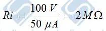
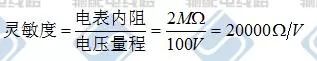
3) The higher the sensitivity, the higher the measurement accuracy of electrical and electronic circuits.
4) The internal batteries usually consist of two: one is a low voltage 1.5V; the other is a high voltage 9V or 15V. The black probe connects to the positive terminal of the internal battery, while the red probe connects to the negative terminal of the internal battery.
5) The allowable current is limited.
2.4 Working Principle
2.4.1 Principle of DC Current Measurement
2.4.2 Principle of DC Voltage Measurement
2.4.3 Principle of AC Current and Voltage Measurement
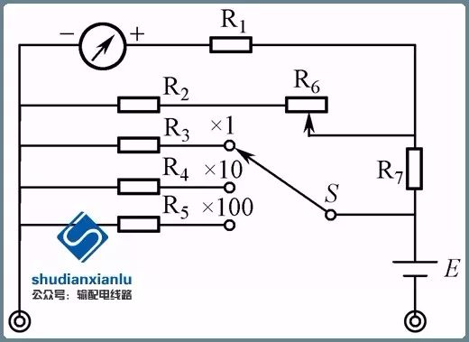
2.4.4 Principle of Resistance Measurement
In addition to the basic parameters mentioned above, some multimeters also include measurements of other parameters, such as voltage levels, capacitance of capacitors, inductance of coils, and the main DC parameters of transistors.
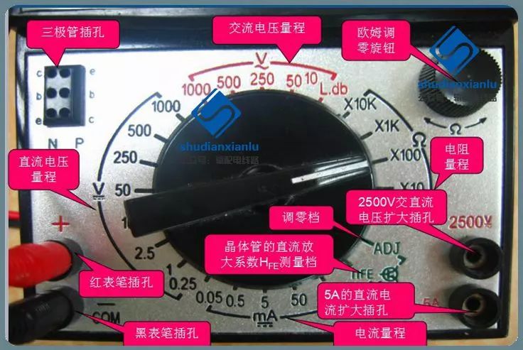
2.5 Introduction to Common MF47 Multimeter Functions
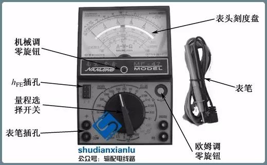
▲ External Structure
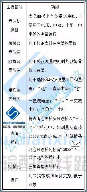
▲ Functional Parts of the Panel
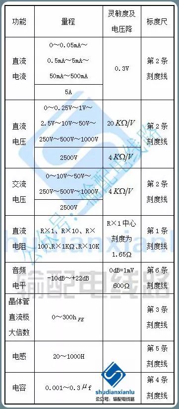
▲ Technical Specifications
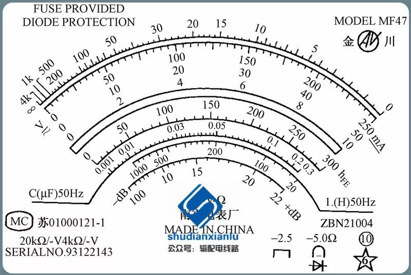
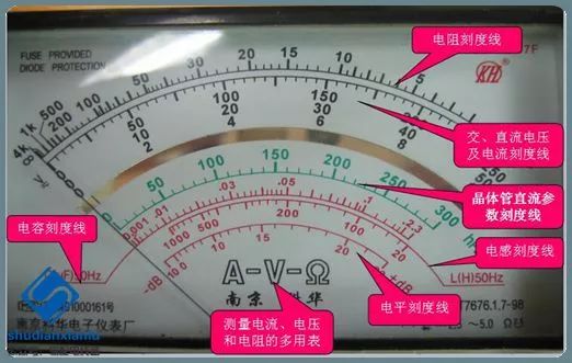
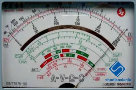
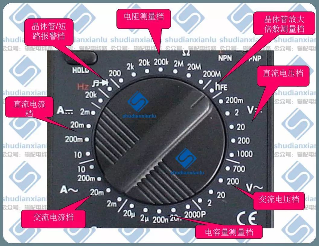
▲ Dial
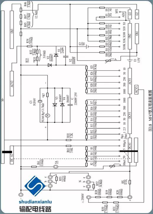
▲ Circuit Diagram
2.6 Preparation Work and Precautions
2.6.1 Preparation Work
(1) Place the multimeter in a vertical or horizontal position according to the requirements indicated by the symbols “⊥” or “Π”, “→” on the meter head.
(2) Check if the pointer is at the zero position on the left end of the dial.
(3) Correctly connect the test leads.
(4) Check the battery level.
2.6.2 Precautions
(1) Do not measure resistance while the component or circuit is powered.
(2) When measuring AC and DC voltage, connect the two probes in parallel; for DC voltage measurement, connect the red probe to the high potential (positive) of the circuit being measured, and the black probe to the low potential (negative).
(3) When measuring DC current, connect the two probes in series, ensuring the red probe connects to the high potential (positive) and the black probe connects to the low potential (negative) of the circuit being measured.
(4) Do not change the range switch during measurement.
(5) During measurement, avoid touching the metal parts of the test leads to ensure safety and measurement accuracy.
(6) Select the appropriate range.
2.6.3 Maintenance
(1) After using the multimeter, if there is no idle position, set the range switch to the highest AC voltage range; if there is an idle position (“*” or “OFF”), set it to that position.
(2) If the multimeter will not be used for an extended period, remove the internal battery to prevent leakage of the battery electrolyte from corroding the internal circuit.
2.7 Method for Measuring Resistance
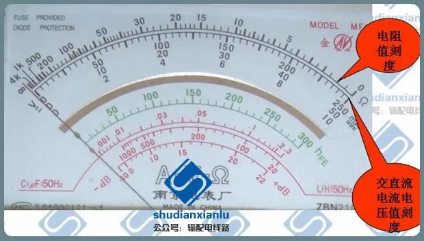
▲ Dial and Scale
Reading Method:
First scale: resistance value scale (read from right to left)
Second scale: AC and DC voltage and current value scale (read from left to right)
2.7.1 Preparation Before Use
1. Install the battery (pay attention to the positive and negative terminals)
2. Insert the test leads correctly. “−” black; “+” red
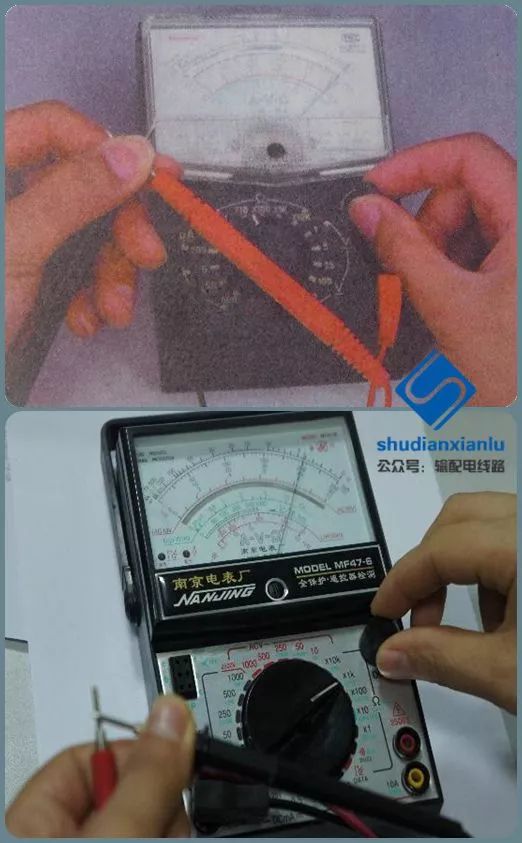
3. Mechanical Zero Adjustment:
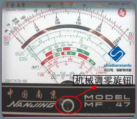
Before measurement, ensure that the meter head pointer is at the zero scale line on the AC/DC scale when placed horizontally; if not at the zero position, adjust it to zero using mechanical zero adjustment, otherwise, the readings will have significant errors.
4. Range Selection:
First step: Rough measurement
Estimate the resistance value being measured roughly, then select the appropriate range. If the resistance value cannot be estimated, generally set the switch to RX100 or RX1K for initial measurement.
Second step: Choose the correct range
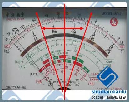
Check if the pointer is near the center line; if so, the range is appropriate. If the pointer is too close to zero, reduce the range; if the pointer is too close to infinity, increase the range.
5. Ohm Zero Adjustment:
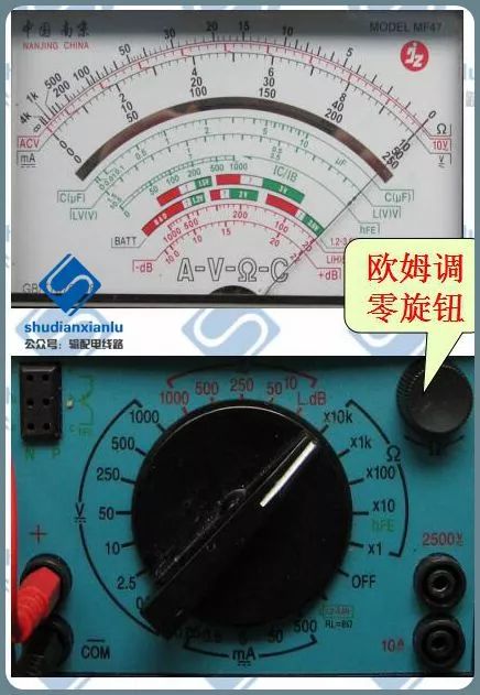
After selecting the range, zero adjustment must be done before formal measurement; otherwise, there will be measurement errors.
Short-circuit the red and black probes and check if the pointer points to the zero scale position; if not, adjust the ohm zero adjustment knob to make it point to the zero scale position.
Note:If the range is changed, zero adjustment must also be done again before formal measurement.
2.7.2 Connection for Resistance Measurement
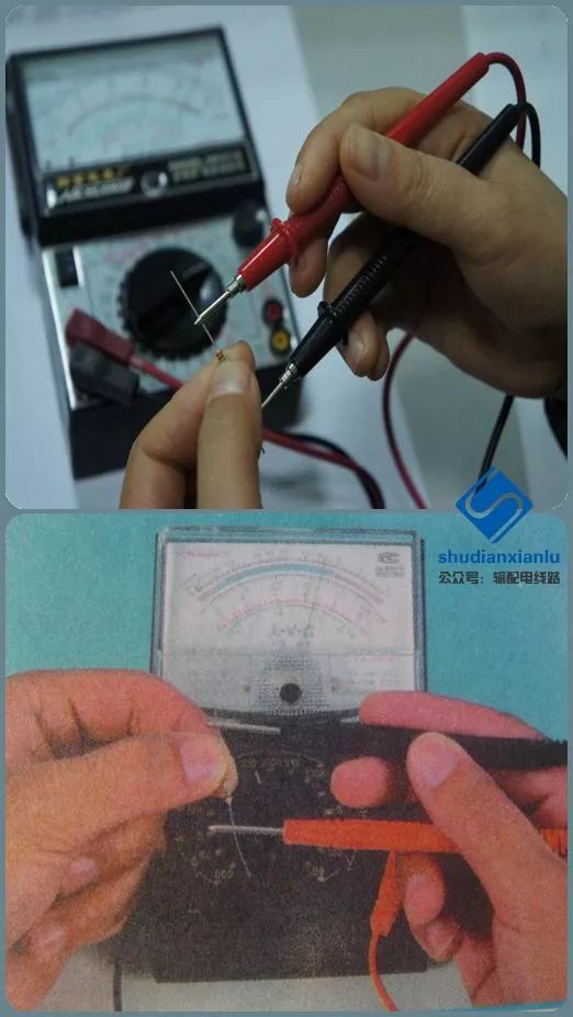
▲ Correct Measurement Method
Note:
1. Do not measure under power;
2. The resistance being measured cannot have parallel branches.
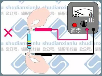
▲ Incorrect Measurement Method
This causes the human body resistance to be in parallel with the resistance being measured.
2.7.3 Reading
Resistance Value = Scale Value ╳ Multiplier
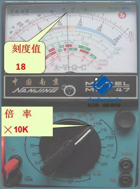
▲ Resistance Value R=18╳ 10kΩ=180kΩ
2.8 Method for Measuring AC Voltage
2.8.1 Preparation Before Use
1. Install the battery.Pay attention to the positive and negative terminals
2. Insert the test leads correctly. “−” black; “+ red
3. Mechanical Zero Adjustment
4. Range Selection:
Rotate the selection switch to the appropriate AC voltage range for measurement. If the approximate value of the voltage to be measured is unknown, rotate the selection switch to the highest AC voltage range for prediction, then switch to the corresponding range for measurement.
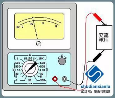
2.8.2 Start Measurement
Connect the two probes across the voltage to be measured (AC voltage does not have positive and negative terminals), as shown in the figure.
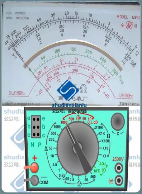
2.8.3 Reading
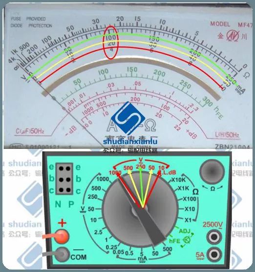
When reading, select the second scale! The second scale has three sets of numbers; which set to read depends on the selected range!
2.8.4 Resetting the Range
When not in use, set the range switch to OFF or to the AC voltage 1000V range.
2.9 Precautions During Operation
1. Before measurement, check if the red and black probes are connected correctly. The red probe should connect to the red terminal or the terminal marked with “+”, and the black probe should connect to the black terminal or the terminal marked with “-”; do not reverse them, as this will cause the pointer to reverse and damage the meter head when measuring DC quantities.
2. Before connecting the probes to the measured circuit, ensure that the selected range matches the measurement object; otherwise, using the wrong range and scale will not only yield no measurement result but may also damage the multimeter. This is a common cause of damage to multimeters, especially for beginners.
3. Before measurement, check if the red and black probes are connected correctly. The red probe should connect to the red terminal or the terminal marked with “+”, and the black probe should connect to the black terminal or the terminal marked with “-”; do not reverse them, as this will cause the pointer to reverse and damage the meter head when measuring DC quantities.
4. Before connecting the probes to the measured circuit, ensure that the selected range matches the measurement object; otherwise, using the wrong range and scale will not only yield no measurement result but may also damage the multimeter. This is a common cause of damage to multimeters, especially for beginners.
3. Usage of Digital Multimeter
3.1 Overview
A digital multimeter is a multi-purpose electronic measuring instrument that generally includes functions such as ammeter, voltmeter, and ohmmeter, sometimes referred to as a multi-meter, multi-use meter, or three-use meter.
Digital multimeters come in portable devices for basic fault diagnosis, as well as devices placed on workbenches, with some resolutions reaching seven or eight digits.
A digital multimeter (DMM) is an electronic instrument used in electrical measurements. It can have many special functions, but its primary functions are to measure voltage, resistance, and current. As a modern multi-purpose electronic measuring instrument, digital multimeters are mainly used in physics, electricity, electronics, and other measurement fields.
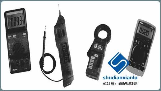
▲ Components of Digital Multimeter
3.2 Structure
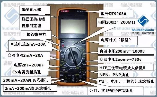
▲ Structure (DT9205A)
The meter head of a digital multimeter generally consists of an A/D (Analog/Digital) conversion chip + peripheral components + LCD display. The accuracy of the multimeter is influenced by the meter head; the multimeter, due to the digital output from the A/D chip, is generally referred to as a 3 1/2 digit multimeter, 4 1/2 digit multimeter, etc. The test leads of the multimeter are usually divided into red and black; when in use, the red probe should be inserted into the terminal marked with a positive sign (+), and the black probe should be inserted into the terminal marked with a negative sign (- or *).
▲ Digital Range Switch
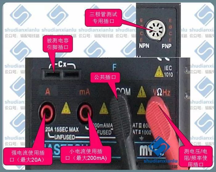
▲ Digital Input
3.3 Classification
According to working principle, there are comparative type, integrating type, V/T type, composite type, etc.; according to usage and form factor, there are bench, portable, pocket, pen, and clamp types, among which pocket types are more commonly used; according to range conversion methods, there are automatic range conversion and manual range conversion; according to purpose and function, there are low-end, mid-range, and smart types.
▲ Classification
3.4 Usage
First Step:
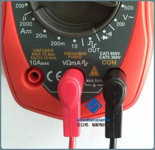
Insert the red probe into the VΩ or mA socket (the above image shows them combined into one socket, as different manufacturers may have variations), and insert the black probe into the COM socket.
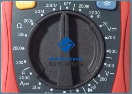
Second Step:
Set the range switch to the appropriate V~ range.
Third Step:
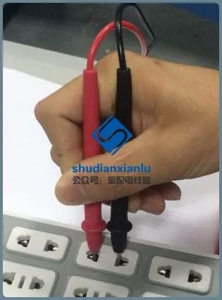
Insert the red and black probes into the appropriate sockets.

Fourth Step:
Read the data displayed on the screen.
Fifth Step:
Set the range switch to OFF (turn off the multimeter).
Note:
When testing mains electricity, ensure the switch is set to the 500V position; the measurement range must always be higher than the voltage being tested. If the voltage to be measured is unknown, start with a higher range and gradually switch to lower ranges as necessary. (Only change ranges after stopping measurement).
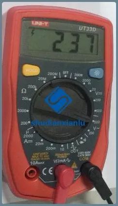
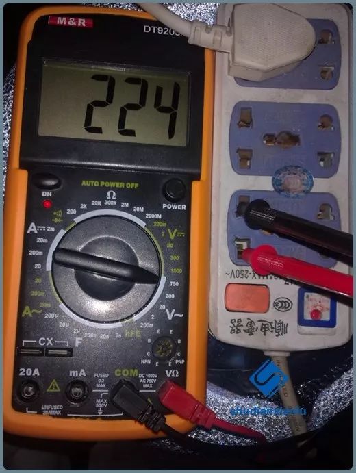
▲ Process of Measuring AC Voltage
3.5 Voltage Measurement
The switch is set to the voltage measurement range, and the red and black probes are connected across the device being measured.
Method:
1) Insert the probes into the corresponding sockets. The red probe goes into the VΩ socket, and the black probe goes into the COM socket.
2) Estimate the voltage level and select the appropriate range. Set the range knob to the V- or V~ position as necessary.
Note: If the exact voltage level is unknown, start with a higher range and work down.
3) During measurement, connect in parallel with the device being measured.
4) Read the data displayed on the screen.
3.5.1 Measurement of DC Voltage
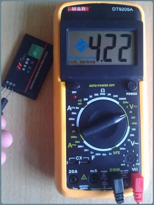
1. Set the knob to a range larger than the estimated value (Note: the DC range is V-, and the AC range is V~). Connect the probes across the power supply or battery terminals; maintain stable contact. The value can be read directly from the display.
2. If the display shows “1.”, it indicates the range is too small, and a larger range should be selected for measurement.
3. If a “−” appears on the left side of the value, it indicates that the probe polarity is opposite to the actual power polarity; in this case, the red probe is connected to the negative terminal.
3.5.2 Measurement of AC Voltage
1. The probe connections are the same as for DC voltage measurement, but the knob should be set to the AC range “V~” for the required range.
2. AC voltage has no polarity; the measurement method is the same as described above.
3. Whether measuring AC or DC voltage, always pay attention to personal safety and avoid touching the metal parts of the probes.
3.6 Current Measurement
The switch is set to the current measurement range, and the measured current flows through the red and black probes.
Method:
1. Disconnect the circuit.
2. Insert the black probe into the COM port and the red probe into the mA or 20A port.
3. Estimate the current level and select the appropriate range (if uncertain, start with a higher range and work down). Rotate the function switch to A~ (AC) or A- (DC), and select the appropriate range.
4. Open the circuit being measured and connect the digital multimeter in series into the circuit; the current from one end flows into the red probe, exits through the black probe, and then returns to the circuit.
5. Reconnect the circuit.
6. Read the numbers displayed on the LCD screen.
3.6.1 Measurement of DC Current
1. Estimate the size of the current in the circuit. If measuring a current greater than 200mA, insert the red probe into the “10A” socket and set the knob to the DC “10A” range; if measuring a current less than 200mA, insert the red probe into the “200mA” socket and set the knob to the appropriate range within 200mA.
2. Insert the multimeter in series with the circuit and maintain stability for reading. If the display shows “1.”, a larger range must be selected; if a “−” appears on the left side, it indicates that the current is flowing into the multimeter from the black probe.
3.6.2 Measurement of AC Current
1. The measurement method is the same as for DC, but the range should be set to AC.
2. After measuring current, remember to return the red probe to the “VΩ” socket; forgetting this step and measuring voltage directly may cause the multimeter or power supply to be damaged beyond repair.
3.6.3 Notes
1. If the current range is unknown before use, set the function switch to the maximum range and gradually decrease it.
2. If the display shows “1”, it indicates over-range, and the function switch should be set to a higher range.
3. The maximum input current is 200mA; excessive current will blow the fuse, which must be replaced. The 20A range has no fuse protection and should not exceed 15 seconds of measurement.
3.7 Resistance Measurement
The switch is set to the resistance measurement range, and the red and black probes are connected across the device (resistor) being measured.
Method:
(1) Insert the probes into the corresponding sockets. The red probe goes into the VΩ socket, and the black probe goes into the COM socket.
(2) Estimate the resistance size and select the appropriate range; set the range knob to the appropriate “Ω” range.
(3) Connect the red and black probes to the metal parts at both ends of the resistor. During measurement, connect in parallel with the device being measured, ensuring the device is powered off during measurement. If the measurement is affected by other devices, disconnect the device from the circuit for measurement.
(4) Read the data displayed on the screen.
Note:
1. Range selection and conversion
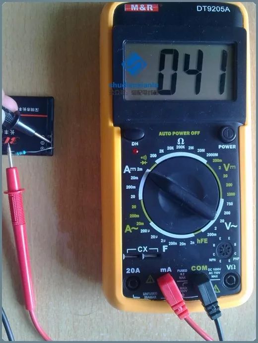
If the range is set too low, the display will show “1.” In this case, switch to a larger range; conversely, if the range is set too high, the display will show a number close to “0”, indicating that a smaller range should be selected.
2. How to read
The number displayed on the screen, along with the unit corresponding to the selected range at the bottom, represents the reading. Note that in the “200” range, the unit is “Ω”, in the “2k~200k” range, the unit is “kΩ”, and in the “2M~2000M” range, the unit is “M”.
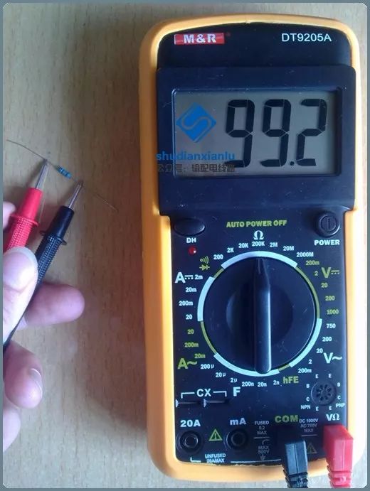
3. If the resistance value exceeds the maximum value of the selected range, “1” will be displayed, indicating that a higher range should be selected. For resistance values greater than 1MΩ or higher, it may take a few seconds for the reading to stabilize, which is normal.
4. If not connected properly, for example, in an open circuit situation, the instrument will display “1”.
5. When checking the impedance of the measured circuit, ensure that all power sources in the circuit are disconnected and all capacitors are discharged. The presence of power sources and energy storage elements in the measured circuit will affect the accuracy of the impedance test.
6. In the 200MΩ range of the multimeter, when short-circuited, it will display 10 digits; when measuring a resistor, subtract these 10 digits from the reading. For example, if a resistor shows 101.0, subtracting 10 digits gives the actual resistance value of 100.0, which is 100MΩ.
———– E N D– ———–