Hello everyone! This is a collection of notes on embedded system development! Recently, the university has entered the final exam week, and suddenly various work-related tasks have come up, sometimes so busy that I can’t even have dinner, and can only update the public account intermittently. I believe everyone has been busy like me lately~ (humorous) In the last article, we spent a long time explaining all the external pins and their functions of the mbed core board, includingSerial, I2C, SPI, CAN, Ethernet, USB, AnalogIn/Out, PwmOut, etc., but we did not discuss how to actually use these modules on the mbed platform. Therefore, this time we will explain the practical application scenarios and programming methods for these pin functions!1. Mbed Application Board – Developing on the Shoulders of GiantsThe pin functions we discussed in the previous article are indeed powerful, but ultimately these functions can be categorized into two main types: one is communication functions represented by Serial, I2C, and SPI, used for data transmission between the mbed core board and other chips; the other is execution functions represented by GPIO, AnalogIn/Out, and PwmOut, used for signal acquisition or action control of other devices. However, a single board cannot achieve much on its own; if we do not have devices to communicate with or control, having just a core board in hand means it cannot perform any functions. Therefore, to achieve more functionalities, we need to connect the various functional pins of the core board to external devices (peripherals) that support the corresponding functions, thereby verifying and implementing the core board’s capabilities.To facilitate quick hands-on development, the mbed official has specially designed an application board that integrates various peripherals for the mbed LPC1768 core board, which we also mentioned in the first article of this series, as shown in the figure below:
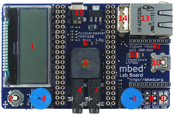 The above image shows the mbed official Application Board, which connects the functional pins of the core board to the peripherals, thus expanding many practical functions based on the core board, and can also be referred to as an expansion board. This application board is about the size of a Raspberry Pi, making it easy to handle. Despite its small size, it actually contains a lot of sensor and actuator modules. The official website for the application board is as follows:https://os.mbed.com/cookbook/mbed-application-boardOn this website, you can also see that the application board integrates various peripherals, as shown in the Feature list below:
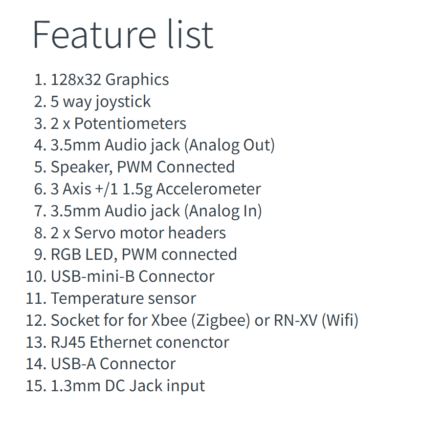 In this list, the numbers in front of each peripheral correspond to the red numbers in the physical image of the application board, allowing for quick reference to the distribution of these peripherals on the application board. The application board includes 1 x 128×32 LCD screen, 5-degree joystick buttons (GPIO), two potentiometers (AnalogIn), 1 x 3.5mm audio output (AnalogOut), 1 x buzzer (PWM), 1 x accelerometer, 1 x 3.5mm audio input (AnalogIn), 2 x servo motor interfaces, 1 x RGB LED (PWM), 1 x USB-mini port, 1 x temperature sensor, 1 x ZigBee/WiFi interface, 1 x RJ45 Ethernet interface, 1 x USB-A port, and 1 x DC power interface.We can connect the mbed LPC1768 core board and the application board together as shown in the figure below, allowing the core board to control these peripherals on the application board.
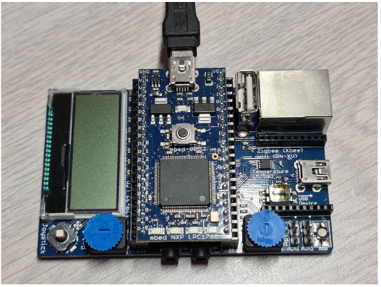 *Note: When using, connect the Micro USB cable to the USB port on the core board, not to the USB port on the application board, otherwise the program cannot be downloaded.Once we connect the core board and the application board together, the output pins of the core board are directly connected to the various peripherals on the application board. The pin connection method between them is provided in the Details table at the bottom of the official website:
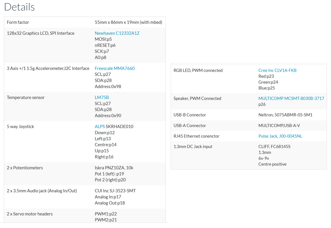 Next, we will provide a few simple examples to explain the correct usage of these peripherals~① LCD – Liquid Crystal DisplayIn the Details table, the first row is the LCD screen: this application board comes with a 128×32 pixel LCD screen, which can display certain information on the core board more intuitively compared to serial tools.From the Details table, we can see that the LCD screen on the application board is connected to the core board’s p5, p6, p7, p8 pins, and from the previous article, we know that one of the typical multiplexing functions of these four pins is SPI communication, so this LCD display is driven and displayed based on the SPI communication interface, which is also indicated in the Details table (SPI Interface).For more information about this LCD screen, you can click on the blue link for Newhaven C12332A1Z in the Details to access the product specification PDF. As shown in the figure below:
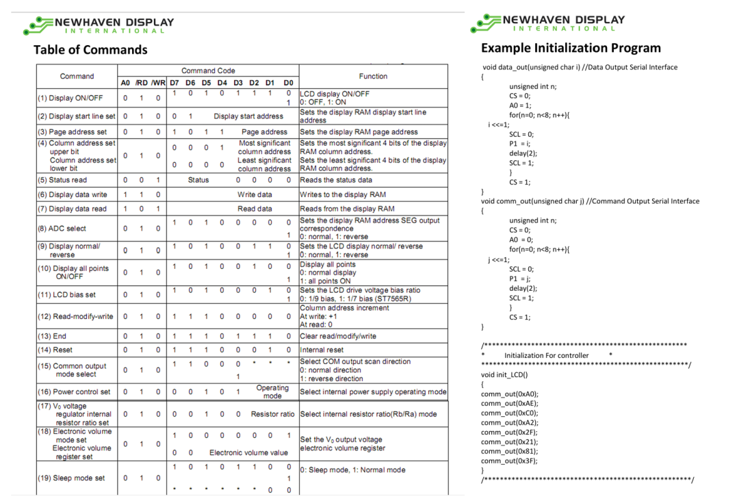 From the product specification, we can obtain detailed information such as the hardware schematic, electrical information, communication timing, etc., and it even provides its initialization routine, as shown in the figure above.To drive this LCD screen to work, we need to send various initialization commands and display data to the LCD via SPI communication, so the driver program for the LCD screen is somewhat complex. If we were to write it ourselves, it would likely take a long time. To facilitate users, the official website of the application board directly provides the LCD library functions and main function examples, as shown in the figure below:
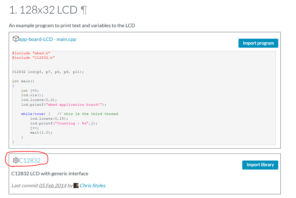 As shown, first click on the circled C12832 to open the webpage link for the LCD library functions, leading to the following page:
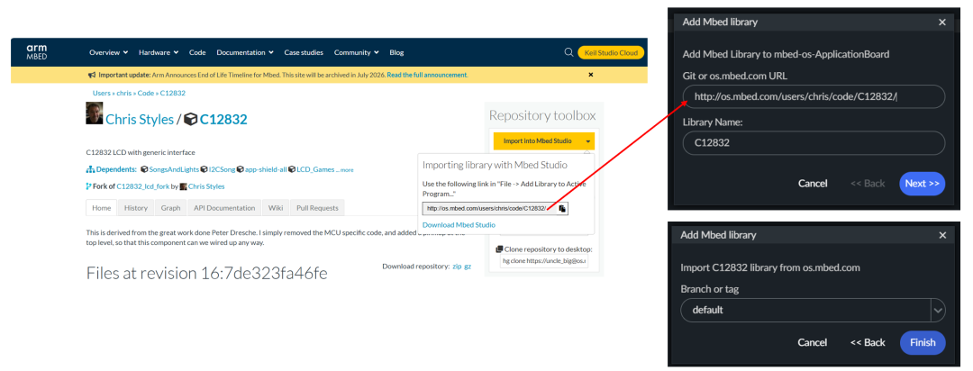 Upon entering the Chris Styles/C12832 library function webpage, we click the yellow “Import Into Mbed Studio”, then copy the link that pops up. Returning to our Mbed Studio project, we click Add Mbed Library, paste the link, name the library as we like (e.g., C12832), select the default version, and click Finish to add this LCD library to our Mbed Studio project.
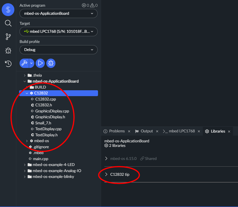 As shown, after successful addition, we can see the source files of the library in the project browser on the left side of Mbed Studio, and in the Libraries window below, we can also find that the C12832 library has been successfully added. Then, we can directly use the function interfaces defined in the library to initialize the LCD and control the display content: we can simply copy the example code from the previous image, app-board-LCD-main.cpp, and paste it into our program project for compilation, download it to the core board, and run it. The running effect is shown in the figure below:
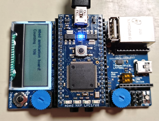 If anyone wants to display other content on the LCD screen, they only need to modify the main function code.② Joystick – ControllerFrom the Details table, we can see that the application board comes with a five-degree joystick (5 way Joysticks), which includes up (up), down (down), left (left), right (right), and center press (center), essentially equivalent to 5 buttons, which are connected to the core board’s p15, p12, p13, p16, p14 pins, used as general input/output GPIO. The position of the joystick on the application board is shown in the figure below.
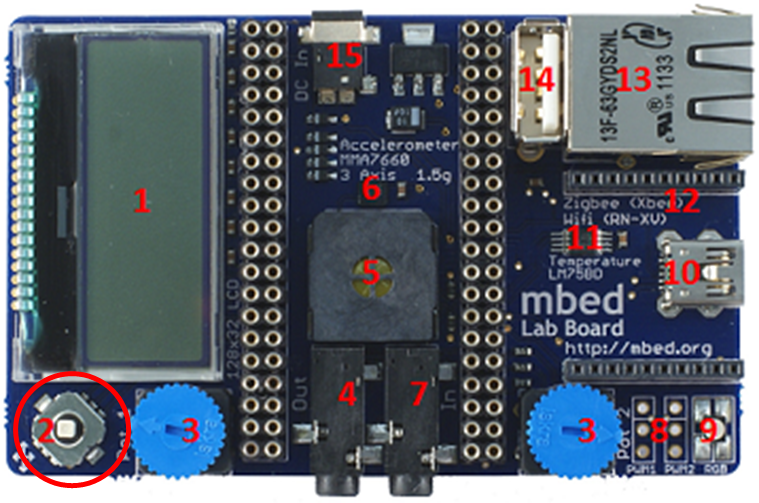 In the second article on mbed, we analyzed in detail how to use the DigitalOut interface in the mbed-os-library to initialize the pins as GPIO output mode to control the on/off of the LED light; here, we will use DigitalIn to initialize these 5 pins as GPIO input to sample the high and low level signals on these pins, thus determining whether the joystick’s five degrees of direction have been pressed. The official website of the application board also provides an example of using the joystick based on the DigitalIn class, as shown in the figure below.
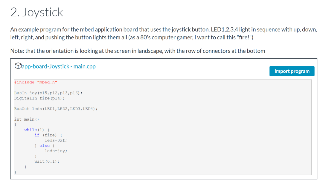 To provide users with a more intuitive demonstration effect, the official website offers a joystick example with a very 80s computer game style: moving the joystick up, down, left, and right will light up the LED1, LED2, LED3, and LED4 on the core board respectively, and pressing the center of the joystick will light up all four LED lights simultaneously, corresponding to “fire”. Everyone can directly copy and paste this example source code into their own project for compilation and download to experience it personally. (The developer of this demo is really childlike~)③ Speaker – Buzzer
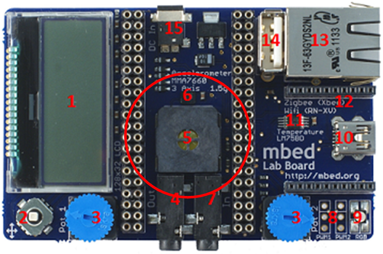 The Speaker is a commonly used buzzer on embedded platforms, located as shown in the figure above. After connecting to the core board, it will be covered by the core board below. In the Details table, we can see that the Speaker is PWM Connected, meaning it is driven by PWM waveforms, and it is connected to the core board’s p26 pin, which is the PwmOut pin we discussed in the previous article.In the mbed-os-library, a complete definition and function interface for the PwmOut related class has already been provided, so we do not need to download and add additional libraries like we did for the LCD screen; we can directly use the PwmOut interface provided in the mbed-os-library to drive the buzzer to produce sound. The official website of the application board also provides an example of using the Speaker:
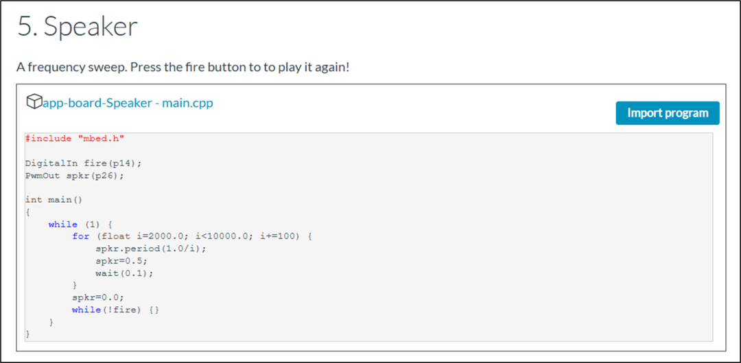 We only need to copy and paste this source code into our program project, compile, download, and run it. When we long-press the Joystick button, we can hear the sound of the buzzer. Among them, spkr.period is its period setting interface. If we want to control the volume of the buzzer, we can directly assign a value to spkr to control the duty cycle of the PWM waveform.④ RGB LED Light
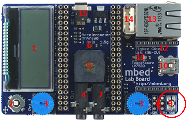 The RGB LED is a type of LED that can produce multiple colors, located as shown in the figure above. This peripheral is also driven by PWM signals, but it connects to three PwmOut pins: p23, p24, p25, driven by three PWM signals. The three PWM signals are connected to the red (red), green (green), and blue (blue) light-emitting units in the RGB bulb, and by changing the duty cycle of the three PWM signals, we can change the brightness of each of the three bulbs, thus allowing the RGB LED bulb to emit different colors of light. The official website of the application board also provides an example, as shown in the figure below:
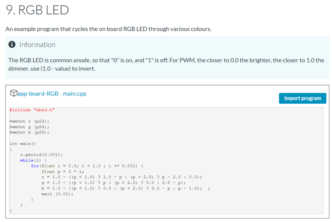 By copying and pasting this example source code into our project, we can compile, download, and run it, and we will find that the LED lights on the application board start to emit colorful lights.⑤ Temperature Sensor
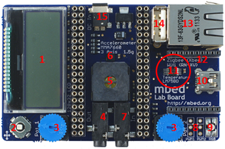 From the Details, we can see that the application board also provides us with a temperature sensor, as shown in the figure. This temperature sensor is connected to the core board’s p27, p28 pins, and these two pins are used as SCL and SDA, so it is easy to see that this temperature sensor communicates via I2C communication.
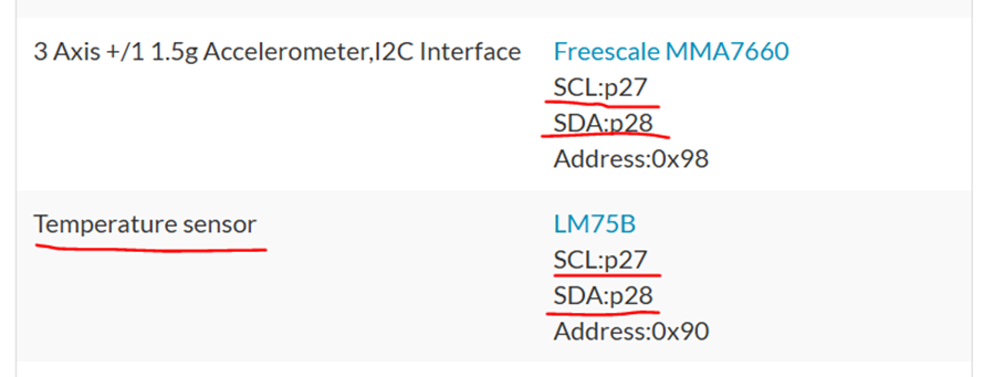 Additionally, have you noticed a detail: not only the temperature sensor but also the accelerometer is connected to the p27 and p28 pins, and both peripherals are connected to the same I2C bus interface, distinguished and identified by their respective addresses, achieving one-to-many communication: If a command is sent to the I2C bus with the address 0x90, then this command will be received and processed by the temperature sensor, and the value from the temperature sensor will be returned on the I2C bus; if the address is 0x98, then the value from the accelerometer sensor with address 0x98 will be returned, just as we mentioned in the previous article.To drive this temperature sensor to work, the official website of the mbed application board also provides library functions and main function examples, as shown in the figure below:
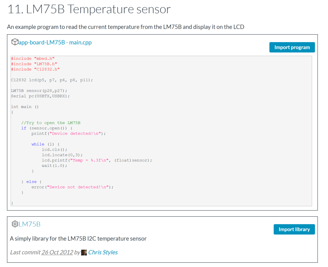 We can follow the method of adding the LCD library mentioned above, first clicking on the image below for LM75B to enter the library function homepage for the temperature sensor, then clicking the yellow “Import Into Mbed Studio”, copying the link that pops up, returning to our Mbed Studio project, clicking Add Mbed Library, pasting the link, configuring the library name and version, and we can add this temperature sensor library to our project, as shown in the figure below.
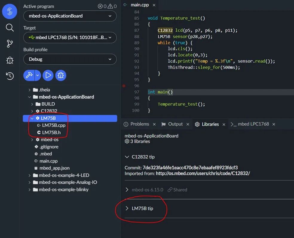 After adding the library functions, we can refer to the example app-board-LM75B-main.cpp main function source code on the official website to build our own program, but directly copying and pasting may cause compilation errors because the main function example code corresponds to a very old version of the mbed-os-library, and now we are using more of the mbed-os 5 or 6 versions in Mbed Studio. Therefore, before building the program, we need to make some simple modifications to this main function source code, and then compile, download, and run it to see the temperature value on the LCD screen.2. Comprehensive Application of the Mbed Application Board – Building Your Own ProjectSo far, we have explained the principles, usage methods, and tips for using various peripherals on the official application board, using commonly used and typical peripheral modules (LCD screen, Joystick, Speaker, RGB LED, Temperature Sensor) as examples. The usage methods for other peripherals are similar to these, and the official website provides main function samples for them, and for more complex peripheral functions, corresponding library functions are also available for download and addition. It can be said that the support for developers from the mbed official website and forum is very sufficient. Since this is the case, we can now integrate the existing peripheral functions of the application board to create our own embedded project! Based on the functionalities of the five peripherals on the application board, we can create a simple “simulated air conditioning system”, but we want it to behave as much like a real air conditioner as possible:
- Since the motor driving the electric fan is controlled by PWM signals just like the buzzer, we can use the Speaker buzzer on the application board to simulate the airflow of the air conditioning fan: the louder the buzzer sounds, the faster the simulated fan spins, and the higher the wind speed.
- Moving the Joystick up/down can turn the air conditioner on/off: if the air conditioner is already on, then pushing the joystick left, pressing the center, or pushing it right can adjust the wind speed to low, medium, or high levels. When the air conditioner is turned on, the default wind speed is low. If the air conditioner is off, the joystick left, center, and right operations will not adjust the wind speed. If the air conditioner is on, pushing the joystick up again to turn it on will have no effect and will not affect the current wind speed level.
- When the air conditioner is on, the RGB LED light will light up green; otherwise, it will light up red.
- Using the temperature sensor, we can obtain the current ambient temperature in real-time.
- On the LCD screen, we can display the ambient temperature and the wind speed level in real-time.
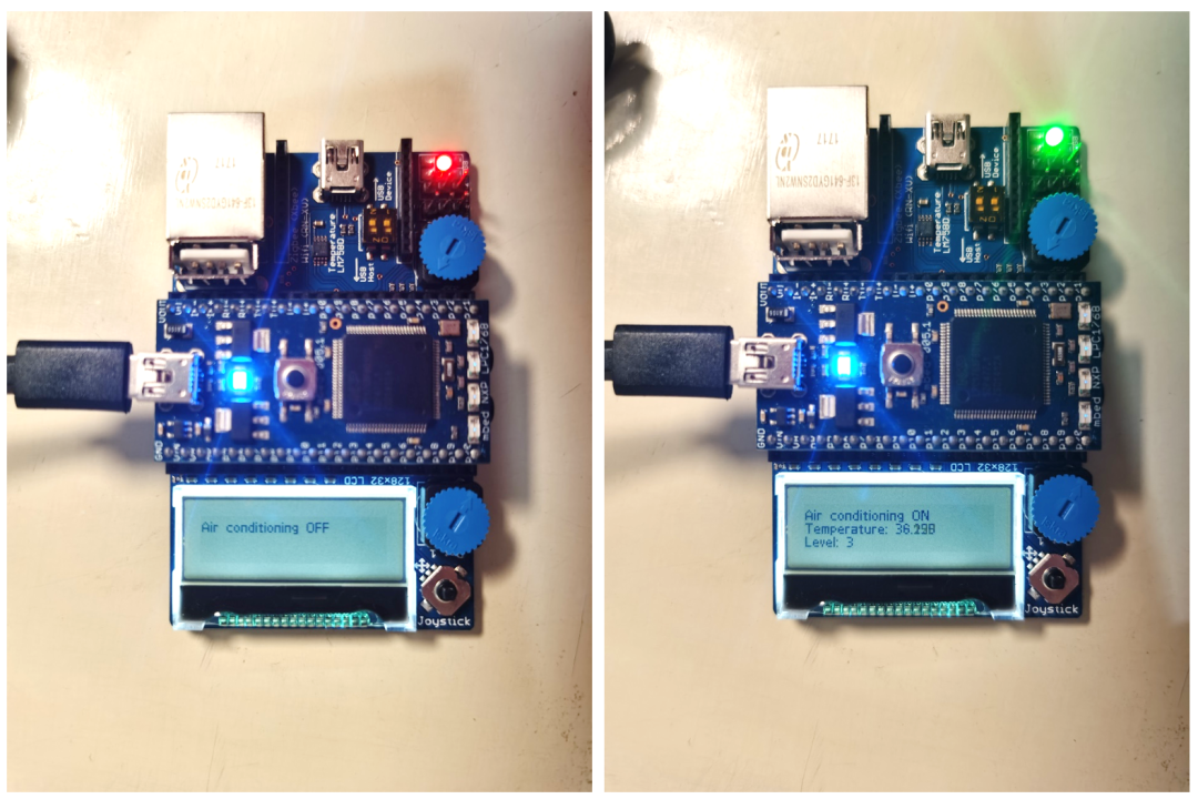 After determining all the peripheral modules and their control logic needed for the “simulated air conditioning system”, we can start creating a new project to develop and program this system! First, we can start with the simple task of writing the function for the Joystick, using if conditions to write its control logic for the system; then, we can program the buzzer, RGB LED, and other peripherals that require PWM signals to achieve color control and volume control; subsequently, we can download the LCD screen and temperature sensor library functions to implement data collection from the temperature sensor and display information on the LCD screen; finally, we can integrate these functions in the main() function of the project using a while(1) loop! The final running effect of the simulated air conditioning system is shown in the figure above.Here, I will intuitively show you the main function that implements all the functionalities, just as a starting point: since the mbed-os-library and peripheral library functions encapsulate the functionalities very well, we can use extremely concise code to directly implement all the above functionalities in the main function:
void simulate_air_conditioner(){    // Initialize Joystick    DigitalIn up(p15);         DigitalIn down(p12);         DigitalIn left(p13);       DigitalIn center(p14);      DigitalIn right(p16);
    bool on, off, small, midium, high;    int state = 0; // get and judge the state of fan 0 - off, 1 - on, 2 - small, 3 - midium, 4 - high    int level = 0; // show and remember the level of fan. 1 -small, 2 - midium, 3 -high    bool need_cls_off = true;  //judge wether LCD need clear screen because LCD.cls cost lot of time.    bool need_cls_on = true;
    // Initialize RGB    PwmOut r (p23);    PwmOut g (p24);    PwmOut b (p25);    r.period(0.001);    g.period(0.001);    b.period(0.001);    r = 0.5; g = 1; b = 1;    // off
    // Initialize Speaker    PwmOut spkr(p26);    spkr.period_us(10000);    spkr = 0.0;     // stop running
    // Iniitalize Temperature Sensor    LM75B sensor(p28,p27);
    // Iniitalize LCD    C12832 lcd(p5, p7, p6, p8, p11);    lcd.cls();
    // Start    while(true)    {        // ThisThread::sleep_for(1ms);        // Scan the Joystick state        on =    up.read();        off =   down.read();        small = left.read();        midium = center.read();        high =  right.read();
        // Judge the state        if(on)        {            state = 1;        }        else if(off)        {            state = 0;        }
        if(state != 0)        {            if(small)                state = 2;            else if(midium)                state = 3;            else if(high)                state = 4;        }
        if(state == 0)  //OFF        {            // RGB in red light            r = 0.5; g = 1; b = 1;             // Speaker stop            spkr.period(0.01);            spkr = 0.0;            // LCD show off            if(need_cls_off){                lcd.cls();                need_cls_off = false;            }            lcd.locate(0,3);            lcd.printf("Air conditioner OFF\n");            need_cls_on = true;        }        else            // ON        {            // RGB in green light            r = 1; g = 0.5; b = 1;             // Speaker in small level default            if(spkr.read() == 0.0){                spkr.period(0.01);                spkr = 0.5;                level = 1;            }            // LCD show temperature            if(need_cls_on){                lcd.cls();                need_cls_on = false;            }            lcd.locate(0,3);            lcd.printf("Air conditioner ON\nTemperature: %.3f\nLevel: %d\n", sensor.read(), level);            need_cls_off = true;              if(state == 2 && level != 1){         // small                spkr.period_us(10000);                spkr = 0.5;                level = 1;                // printf("speaker:%d\n",spkr.read_period_us());            }                  else if(state == 3 && level != 2)     // midium            {                spkr.period_us(5000);                spkr = 0.5;                level = 2;                // printf("speaker:%d\n",spkr.read_period_us());            }              else if(state == 4 && level != 3)     // high            {                spkr.period_us(1000);                spkr = 0.5;                level = 3;;                // printf("speaker:%d\n",spkr.read_period_us());            }         }    }}
int main(){    simulate_air_conditioning();}
Thus, we have learned to program and develop various peripherals based on the mbed application board. The official website of the mbed application board provides examples for almost all peripherals, and for more complex peripherals, corresponding library functions are also provided, which can be added to our projects through copying, pasting, or git links. Users can conduct in-depth research and tracing of these officially provided codes, which can better help them learn the working principles, configuration processes, and usage methods of peripheral modules, assisting everyone in getting started and developing their own embedded systems more quickly.However, learning how to use each peripheral is only the first step in embedded system development; merely knowing how to use each peripheral is far from enough, as embedded system development often does not end with just completing a single function. Its purpose is often to integrate multiple functions onto a small board. Therefore, how to organically integrate all functions together and ensure that the system responds quickly and runs smoothly is also a discipline. If you actually run the above code, you will find that the entire system’s response to joystick operations is very slow, because we have almost thrown all the execution codes of the functionalities into the while(1) loop. This code seems very concise, but the efficiency of system execution is indeed too low; although it works, it is really too weak. Therefore, how to ensure the overall performance of the embedded system while adding so many peripheral functions, and whether there is a better way to integrate peripherals, we will explain in the next article! Here, I also wish all students a smooth exam week, overcoming all difficulties! The summer vacation is just around the corner~