Click the blue text above, select “Set as Favorite”
Reply “666” to get the interview guide

Computer networks are a fundamental course, but what the teacher talks about is merely a way to spark interest. However, for those who need to self-study, it is undoubtedly more challenging. The road ahead is long~~
Computer networks are inherently dull, and the article is lengthy, so I recommend readers to patiently finish this article. I hope everyone can gain something after reading it. Let me first outline the general structure of this article.
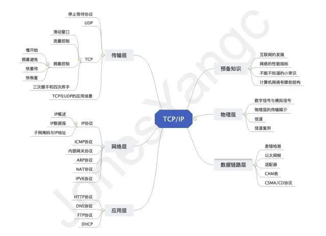
Prerequisite Knowledge
The book “Computer Networks” by Xie Xiren is a widely chosen textbook for computer networks in many universities. The first chapter is an introduction that roughly discusses the development of computer networks, which can be said to be common knowledge that everyone must understand. Here, I will summarize it as preparatory knowledge for studying computer networks.
A Brief History of the Internet
- First Stage: 1950s, research on data communication technology and network theory fundamentals
- Second Stage: 1960s, ARPANET and packet-switching technology
- Third Stage: Mid-1970s, standardization of network architecture and network protocols
- Fourth Stage: 1990s, development of the Internet, high-speed networks, wireless networks, mobile Internet, and network security technology
Development of the Internet
“The development of computer networks has mainly gone through the following seven stages.”
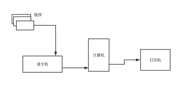
“Batch Processing”: To allow more people to use computers, batch processing systems emerged. Batch processing refers to the preloading of user programs and data into tapes or cards, which the computer reads in a certain order.
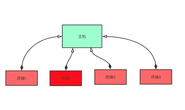
“Time-Sharing Systems”: After batch processing systems, time-sharing systems appeared. This means that multiple terminals are connected to a computer simultaneously, allowing multiple users to use the computer at the same time.
-
“Computer Communication Technology”: In time-sharing systems, we see the connection between terminals and computers, but this does not mean that computers are interconnected. With the increasing number of computers, the convenience of data exchange between computers has become increasingly important. Initially, the process of exchanging data between two hosts was quite cumbersome. Hence, computer communication technology (where computers are connected by communication lines) was born. People can easily and instantly read data from another computer, greatly shortening the time for data transmission.
-
“The Birth of Computer Networks”: In the 1970s, people began experimenting with computer networks based on packet-switching technology and started researching the technology for different manufacturers’ computers to communicate with each other. By the 1980s, a network that could interconnect various computers emerged. Network communication technology entered the fast lane of development.
-
“The Popularization of the Internet”: Entering the 1990s, with the decreasing price and increasing performance of computers, various applications emerged, leading to a higher degree of computer penetration. In response to this trend, manufacturers not only had to ensure the interoperability of their products but also focused on continuously making their network technology compatible with Internet technology (TCP/IP).
-
“The Internet Era”: With the popularization of the Internet, people have become increasingly reliant on it. Life, study, and work all depend on network information; the era of everything being interconnected has long arrived.
-
“The Era of Network Security”: The Internet has brought about revolutionary changes to the world, greatly facilitating people’s daily lives. The Internet presents a highly convenient information network environment to modern people, which has become an essential resource for countries, akin to water, electricity, and gas. With the interconnection of everything, network security is bound to be a crucial part of national security. In the early days of the Internet’s popularization, people were more concerned about pure connectivity and focused on establishing connections without any restrictions. But now, people are no longer satisfied with mere “pure connectivity” but are more in pursuit of “secure connectivity.”
Performance Indicators of Networks
-
“Bit”: A bit is a unit of data quantity in computers and also a unit of information used in information theory. The English word bit comes from binary digit, meaning a “binary number.” The rate in network technology refers to the speed at which hosts connected to a computer network transmit data over a digital channel, also known as data rate or bit rate.
-
“Bandwidth”: In computer networks, bandwidth is used to indicate the capacity of the communication line to transmit data, so network bandwidth indicates the “maximum data rate” that can be transmitted from one point in the network to another in a unit of time. The unit of bandwidth in this sense is bits per second.
-
“Throughput”: Throughput refers to the amount of data transmitted through a network (or channel, interface) in a unit of time, indicating the current capability of the network to transmit data.
-
Delay:
- 1. “Transmission Delay”: Refers to the time required for a host or router to send a data frame, which is the time from the first bit of the data frame being sent to the last bit being sent.
- 2. “Propagation Delay”: Refers to the time required for electromagnetic waves to propagate a certain distance in the channel.
-
“Delay-Bandwidth Product”: The delay-bandwidth product indicates the number of bits that the link can accommodate, thus the delay-bandwidth product of the link is also called the link length in bits.
-
“Round-Trip Time (RTT)”: Round-trip time (RTT) refers to the total time from when the sender starts sending data to when the sender receives the acknowledgment from the receiver (the receiver immediately sends an acknowledgment after receiving the data). The round-trip time generally includes various delays of packets in the network.
-
“Utilization”: Utilization can be divided into channel utilization and network utilization. Channel utilization indicates the percentage of time a channel is utilized (data is transmitted). The utilization of a completely idle channel is zero. Network utilization is the weighted average of the channel utilization of the entire network. Higher channel utilization is not always better because, according to queuing theory, as the utilization of a channel increases, the delay caused by that channel also increases rapidly. Excessive utilization of a channel or network can lead to significant delays.
Must-Know Common Knowledge
Classification of Computer Networks
According to “Geographical Coverage”, computer networks can be classified into three parts:
- “Local Area Network (LAN)”: Common networks in offices, dormitories, or internet cafes are LANs, typically within a few meters to 10 km. Their characteristics include: narrow connection range, few users, easy configuration, and high connection speed.
- “Metropolitan Area Network (MAN)”: Used to connect the LANs of enterprises, agencies, or schools within a city or region to achieve resource sharing within the area.
- “Wide Area Network (WAN)”: Also known as a remote network, WAN interconnects LANs or MANs in different cities. Due to the long distances, information attenuation is significant, so such networks generally need to rent dedicated lines and connect through special protocols, forming a mesh structure. Because WAN connects many users, the connection speed for each user is generally lower.
Topological Structures of Computer Networks
-
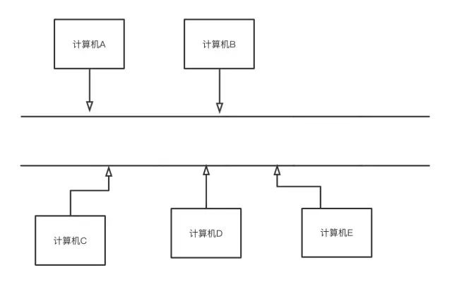
Bus Structure
:
-
Advantages: Low cost, easy to expand, high line utilization;
-
Disadvantages: Low reliability, difficult maintenance, low transmission efficiency.
-
Ring Structure
:
- Advantages: Token control, no line competition, strong real-time performance, easy transmission control;
- Disadvantages: Difficult maintenance, low reliability
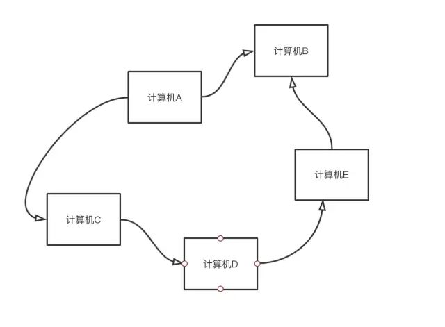
- Star Structure
- Advantages: High reliability, easy management, easy to expand, high transmission efficiency.
- Disadvantages: Low line utilization, the central node requires high reliability and redundancy.
What Structures Do Computers Have?
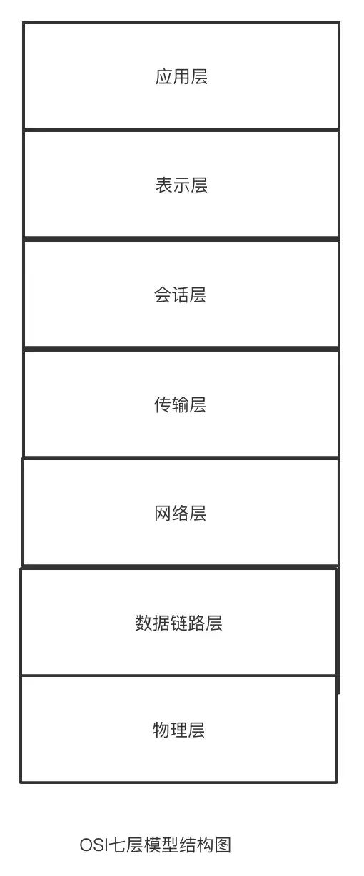
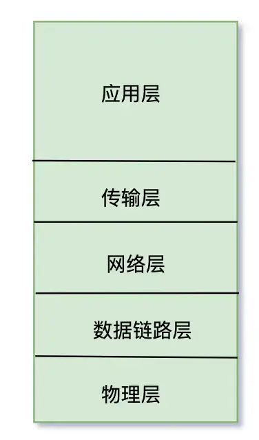
There are three different layered models of computer networks:
-
“OSI Seven-Layer Model”
-
“Five-Layer Structure Model”
- “TCP/IP Layered Structure Model”
The TCP/IP protocol is the protocol followed by the current Internet. It is not merely composed of TCP or IP, but consists of protocols from various layers, forming what we commonly refer to as the TCP/IP protocol stack. However, for better understanding, the subsequent articles will also be written according to the five-layer protocol.
Physical Layer
Here is a suggestion: when studying computer networks, one should not study each network protocol in isolation but should understand the reasons for its emergence and its role in the entire computer network.
Digital Signals and Analog Signals
The role of this is to shield the differences between different transmission media and communication methods. We all know that there are basically two types of signals in nature: one is digital signals, and the other is analog signals. So, what are analog signals? What are digital signals?
In simple terms, analog signals are continuously varying physical quantities. The characteristic of analog signals is that their amplitude is continuous (the continuity means that within a certain range of values, an infinite number of values can be taken). The waveform of analog signals is also continuous over time, thus it is also a continuous signal. When we sample continuous signals, we obtain sampled signals, but abstract signals are discrete (talking about this brings us to signal systems; it seems that the makeup exam has indeed influenced me). However, digital signals differ from analog signals in that they are discrete in the time domain and have two different states represented by “0” and “1”. This is akin to a light switch, which also has two different states.
Of course, digital signals and analog signals can be converted into each other. Analog signals are usually quantized and converted into digital signals using PCM (Pulse Code Modulation) methods. PCM methods correspond different ranges of analog signals to different binary values. Typically, digital signals are obtained through phase-shift modulation of carriers.
Transmission Media of the Physical Layer
We all know that the transmission media for data at the physical layer is different, and the device working at the physical layer is “Hubs”. However, they can generally be divided into two categories:
- “Guided Transmission Media”: Guided transmission media includes various types such as coaxial cables, optical cables, and twisted pairs, among which twisted pairs can be further subdivided based on whether they are shielded.
- “Unguided Transmission Media”: Unguided transmission media refers to the propagation of radio waves in space, using different frequency bands to transmit different signals.
Channels
Speaking of channels, the previous basic section mentioned the utilization of channels, but a more detailed introduction to channels was not provided, so let’s take a closer look. According to the transmission media, channels can be divided into three categories:
- “Wired Channels”: Wired channels use wires as transmission media, and signals are transmitted along the wires, with signal energy concentrated near the wires, thus achieving high transmission efficiency, but deployment is not flexible enough. This category of channels includes overhead wires transmitting electrical signals, telephone lines, twisted pairs, symmetrical cables, and coaxial cables, as well as optical fibers transmitting modulated light pulse signals.
- “Wireless Channels”: Wireless channels mainly include radio channels that use radiated radio waves as the transmission method and underwater channels that propagate sound waves. Radio signals are radiated by the transmitter’s antenna to propagate throughout free space. Different frequency bands of radio waves have different propagation methods.
- “Storage Channels”: In a sense, storage media such as tapes, discs, and disks can also be considered a type of communication channel. The process of writing data to storage media is equivalent to the process of a transmitter sending signals to the channel, while the process of reading data from storage media is equivalent to the receiver receiving signals from the channel.
Channels are the means of transmitting information, and channel capacity describes the maximum capability of a channel to transmit information without error, which can be used to measure the quality of a channel.
Another important parameter concerning channels is the signal-to-noise ratio. The higher the signal-to-noise ratio, the greater the channel’s capacity. Here is Shannon’s famous formula:

Where C is the channel capacity, B is the bandwidth, and S/N is the signal-to-noise ratio.
Channel Multiplexing
We know that when there is no data being transmitted, the channel is quite idle. However, when there is a high demand for network data requests, such as during recent sales events, the speed of information transmission can be hindered. So what is channel multiplexing? Multiplexing means reusing. Channel multiplexing can be divided into several aspects:
- “Time Division Multiplexing”: Time division multiplexing means dividing the entire channel into different time slots. When time division multiplexing is used, all users occupy the same frequency bandwidth at different times (dividing time without dividing frequency). Time division multiplexing may lead to waste of line resources.
- “Frequency Division Multiplexing”: Frequency division multiplexing means dividing signals into different frequencies. When frequency division multiplexing technology is used, all users occupy different bandwidth resources at the same time. When frequency division multiplexing technology is used, all users occupy different bandwidth resources at the same time.
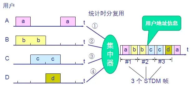
- “Statistical Time Division Multiplexing”: Statistical time division multiplexing systems can also be referred to as asynchronous time division multiplexing systems. They have a buffer-like mechanism that only forwards data when a certain amount of data arrives, greatly improving channel utilization.
Data Link Layer
Ethernet Frame
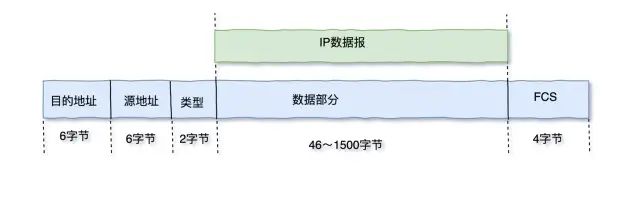
The data link layer receives IP datagrams from the network layer and encapsulates them so that the IP datagrams can be transmitted at the data link layer. The encapsulated IP datagrams are called Ethernet frames, also known as MAC frames. A MAC frame consists of the following important parts:
- “Destination MAC Address”: The destination address of the MAC frame occupies 6 bytes, indicating the address of the target host.
- “Source MAC Address”: Like the destination address, the source address also occupies 6 bytes, indicating the address of the source host.
- “Type”: The type occupies 2 bytes, recording the protocol used by the upper layer, with 0X0800 indicating the IP protocol.
- “Data Portion”: The data portion naturally comes from the upper layer’s IP datagram.
- “FCS”: FCS occupies 4 bytes and is used for error detection. If a MAC frame encounters an error, it cannot be sent to the destination host.
Error Detection
Why do we need to perform error detection?
Real communication links are not ideal. This means that bits may encounter errors during transmission: 1 may turn into 0, and 0 may turn into 1, which is called bit error. The ratio of the number of bits transmitted incorrectly to the total number of bits transmitted in a period is called the Bit Error Rate (BER). The BER is closely related to the signal-to-noise ratio, and in actual communication, it is impossible to reduce the BER to zero. Therefore, to ensure the reliability of data transmission, various error detection measures must be adopted when transmitting data in computer networks.
Errors inevitably occur during the propagation of MAC frames. As mentioned earlier in the Ethernet frame section, we can determine whether a MAC frame has encountered an error or been lost based on the FCS.
Later, when we discuss the transport layer, we will also mention error detection. So what is the difference between the two? In summary, we can say:
- The error detection at the data link layer aims for “no bit errors.”
- The error detection at the transport layer aims for “no transmission errors,” which means compensating for frame loss, frame duplication, and frame disorder.
There are two main methods of error detection: Parity Check (PCC) and Cyclic Redundancy Check (CRC). PCC is very simple and is not the focus of this article. Below we will mainly discuss CRC cyclic redundancy check.
Cyclic Redundancy Check is a method that generates a fixed-length check code based on the data being transmitted or stored, mainly used to detect or verify errors that may occur during data transmission or storage. The generated number is calculated and attached to the data before transmission or storage, and the receiving end checks to determine whether the data has changed.
Through CRC, we can calculate the FCS redundancy check code, which is located at the end of the MAC frame. Through the FCS, we can determine whether this MAC frame has been sent with errors.
Adapters
Speaking of adapters, we can completely associate them with adapters in our daily life. For example, when we charge our phones, we need a power adapter. The power adapter serves merely as a converter or as a carrier to achieve energy transfer. In fact, the adapters in computers serve the same purpose. Let’s understand it with the following diagram:
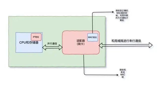
We all know that data is transmitted serially in external media, while computers process internal instructions in parallel. How to convert serially transmitted data into parallel transmission? This requires an adapter. The adapter acts like a bridge, enabling easy conversion of data transmission methods.
CAM Table
We all know that switches are multi-port bridges that use MAC addresses to forward data at the data link layer. In switches, there is a table called the CAM table that does not actually store any information. This table records the MAC addresses of hosts and their corresponding interfaces. Take a look at the diagram below:
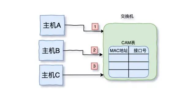
There are three hosts A, B, C connected to the switch. Initially, the CAM table does not store any information.
One day, host A (source MAC) wants to send a message to host B (destination MAC). At this point, the switch will check its CAM table to see if it has stored information about host A. The switch finds that there is no information about A, so it writes A’s information into its CAM table. Now, the switch’s CAM table looks like this:
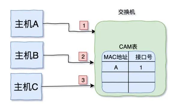
At this point, the switch’s CAM table has stored information about host A, but host A wants to send a message to host B. What should we do? “First”, the switch will check its CAM table to see if there is information about B, “If it exists”, it will directly forward the information to B. “If it does not exist”, what should we do? After some hesitation, the switch has another idea, it broadcasts the message from host A to host B to all hosts connected to it. Host C also receives this message, but host C checks the destination address and finds it is not for itself, so it discards the message. Host B receives this message and also checks the recipient (destination address), finds it is for itself, and thus accepts the message. Afterwards, the switch updates its CAM table, adding one more piece of information:
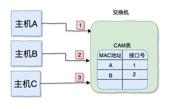
Thus, the CAM table now stores information about hosts A and B. Next time host A wants to send a message to host B, the switch does not need to broadcast anymore.
CSMA/CD Protocol
As of now, the use of CSMA/CD is quite rare, and it is used in the following two places:
- Used in wired networks
- Applied in 10M/100M half-duplex wired networks
“Networks using CSMA/CD have the following three characteristics:”
- “The network is a bus structure”, where all computers are connected to the same bus, and at the same time, only one computer is allowed to send (or receive) messages, which means half-duplex communication.
- “Carrier Sensing”: Before and during transmission, the channel must be continuously monitored, and a message can only be sent when the channel is idle.
- “Collision Detection”: The host will continuously monitor the channel before and during message transmission. If two hosts send messages simultaneously, the transmission of messages will stop immediately. After a random wait, they will retransmit the messages, which is the backoff algorithm.
“Let’s add some characteristics of the backoff algorithm:”
- “Non-persistent CSMA”: If the line is busy, wait for a while before listening again; if it’s idle, send immediately; reduces conflicts, but decreases channel utilization.
- “1-persistent CSMA”: If the line is busy, continue to listen; if it’s idle, send immediately; increases channel utilization, but increases conflicts.
- “p-persistent CSMA”: If the line is busy, continue to listen; if it’s idle, send with probability p, with the remaining probability of 1-p to continue listening (p is a designated probability value).
Network Layer
IP Protocol
Overview of IP
The IP protocol corresponds to the IP address. So what is an IP address?
Wikipedia explains it as follows:
❝
An IP address (English: IP Address, full name: Internet Protocol Address), also translated as Internet Protocol address. When a device connects to the network, it is assigned an IP address as an identifier. Through the IP address, devices can communicate with each other; without an IP address, we would not know which device is the sender and which is the receiver. IP addresses have two main functions: identifying devices or networks and addressing.
❞
The above text essentially explains two points, summarized as follows:
- The IP address is used to mark the address of the host. Without an IP address, the host cannot be identified (marking the host).
- Because it uniquely marks the host, it can be used to locate the host in the network (addressing).
Now, think about what we discussed earlier regarding MAC addresses. A MAC address is a symbol of identity for a host. Once a host leaves the factory, its MAC address is uniquely determined and cannot be changed (of course, it can be modified through software, but it must ensure that there are no two hosts with the same MAC address in the same LAN).
“So, why do we need an IP address if we already have a MAC address? Or conversely, why do we need a MAC address if we already have an IP address?”
This is actually a classic question, and there are many answers online. Here are two recommended articles:
- Why do we need MAC addresses when we have IP addresses?
- Why do we need IP addresses when we have MAC addresses?
After reading these two articles, I summarize as follows:
- “Historical Reasons:” Ethernet was born before the Internet, and MAC addresses were already in use before IP addresses. The combined use of both is to avoid affecting existing protocols.
- “Layered Implementation:” After layer separation of network protocols, the implementation of the data link layer does not need to consider the forwarding of data between layers, and the implementation of the network layer does not need to consider the influence of the data link layer.
- “Division of Labor:” IP addresses change as hosts connect to different networks, while MAC addresses generally do not change. Thus, we can use IP addresses for addressing, and when the datagram and destination host are in the same network, use MAC addresses for data delivery.
IP Datagram
The format of an IP datagram is as follows:
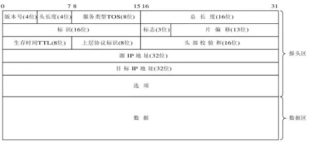
There are several important points that need to be explained:
- “Version Number”: Occupies 4 bits, indicating the version of the IP protocol used by this IP datagram. The main version used on the Internet is IP version 4 from the TCP/IP protocol suite.
- “Header Length”: Occupies 4 bits; this field indicates the length of the entire header (including options), measured in units of 32-bit binary numbers. The receiving end can use this field to determine where the header ends and where to start reading data. A standard IP datagram (without any options) has a value of 5 (i.e., a length of 20 bytes).
- “Type of Service”: Occupies 8 bits, used to specify how this datagram should be processed.
- “Time to Live (TTL)”: Occupies 8 bits, indicating the maximum time this datagram can be transmitted in the network. In practice, the TTL field is set to the maximum number of routers the datagram can pass through. The initial value of TTL is set by the source host (usually 32, 64, 128, or 256). Each time it passes through a router that processes it, its value decreases by 1. When this field reaches 0, the datagram is discarded, and an ICMP message is sent to notify the source host, thus preventing the datagram from being endlessly transmitted in a loop.
- “Upper Layer Protocol Identifier”: Occupies 8 bits; the IP protocol can carry various upper layer protocols, and the target end can route the received IP datagram to upper layer protocols like TCP or UDP based on the protocol identifier.
For a more detailed article on IP datagrams, you can refer to this article: Detailed Explanation of IP Datagram Format.
Subnet Mask and IP Address
When discussing the components of an IP address, we mentioned the network number. Common IP addresses are composed of network addresses and host addresses. So what is a network number? The network number is the name of the network where the computer currently resides, which consists of many hosts. How to calculate the network number? This is where the subnet mask comes into play.
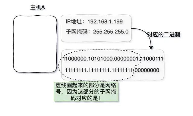
Typically, an IP address and its subnet mask appear in pairs. By comparing the subnet mask with the IP address, we can determine the host number and network number. For convenience, the subnet mask is usually represented with consecutive 1s followed by consecutive 0s, and there should not be alternating 0s and 1s.
See the example below.
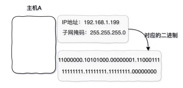
Now that we know the IP address and subnet mask of host A, we can convert them into binary form. By matching the binary subnet mask’s 1s with the IP address, we can identify the network number, while the 0s in the subnet mask correspond to the host number. The following diagram illustrates this clearly:
ICMP Protocol
We know that the IP protocol is an unreliable transmission protocol, while the TCP protocol ensures reliable transmission in the network. So how does the network layer handle situations where messages are not delivered? This is where the ICMP protocol comes into play. What is the ICMP protocol? ICMP stands for Internet Control Message Protocol.
Its function is to more effectively forward IP datagrams as the data part of the IP datagram, which can be divided into ICMP error messages and ICMP query messages. Error messages are used to report errors simply, while how to handle errors is the responsibility of higher-level protocols. Also, error messages are always sent back to the original data source (because the only usable addresses in ICMP datagrams are the source IP and destination IP), and query messages always come in pairs.
ARP Protocol
Earlier, we mentioned that IP addresses are used for addressing, while MAC addresses are used for delivering datagrams when the destination address and datagram are on the same network. Now, suppose host A wants to send a message to host B. The message has gone through a series of forwarding and finally found host B’s IP address. However, we all know that data transmission at the link layer requires a MAC address; knowing only B’s IP address is insufficient for communication. See the diagram below:
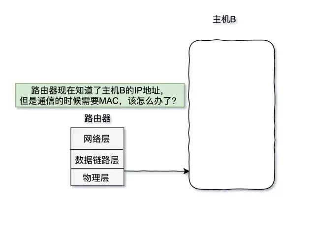
At this point, the ARP protocol comes into play. ARP stands for Address Resolution Protocol, and its basic function is to query the MAC address of the target device through its IP address to ensure smooth communication. It is an indispensable protocol in IPv4 network layers.
“Just as switches operate at the data link layer, routers operate at the network layer. Switches have CAM tables, and routers have routing tables.”
Now, in order for the router to send a message to host B, it must know host B’s MAC address to communicate. At this point, the router will send an ARP request, which is broadcast to all hosts connected to that router. However, only host B checks its IP address and finds it matches the requirement. Therefore, host B sends an ARP response back to the router, telling it its MAC address. This is illustrated in the diagram below:
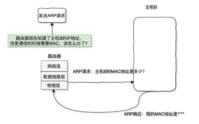
Each time the router sends an ARP request, it adds a piece of data that records the MAC address corresponding to the IP address. This way, the next time the router needs to send a message to that host, it does not need to broadcast anymore. Of course, just as the data in the CAM table has a lifespan, the data in the routing table also has a lifespan. Imagine if data persisted indefinitely, the router would need to use a lot of storage space to cache outdated data.
Interior Gateway Protocols
The main routing protocols on the Internet are RIP and OSPF. Below is a detailed introduction to these two protocols.
“First, let’s introduce the RIP protocol:”
- Routing Information Protocol (RIP) is the first widely used protocol in the Interior Gateway Protocol (IGP). RIP is a distributed, distance-vector based routing protocol and is a standard protocol for the Internet. Its main advantage is its simplicity and low overhead.
- Basic Algorithm: The vector distance algorithm (abbreviated as V-D algorithm) works on the principle that gateways periodically broadcast path refresh messages, which mainly consist of several (V, D) pairs; V represents the gateway that can reach the destination (gateway or host), and D represents the distance, indicating the number of hops to reach destination V. Other gateways update their routing tables based on the shortest path principle upon receiving the (V, D) messages from a gateway.
- RIP is only suitable for small networks (15 hops is the limit). If the network is too large, it takes a long time for the information about a fault to be transmitted to all routers.
“Next, let’s talk about OSPF:”
- Basic Definition: OSPF (Open Shortest Path First) is an Interior Gateway Protocol (IGP) used to make routing decisions within a single autonomous system (AS).
- Basic Algorithm: Dijkstra’s algorithm. It mainly establishes neighbor relationships by sending HELLO packets to neighbors and selecting DR, etc.
Reference Article: Comparison of Routing Principles in Computer Networks: RIP and OSPF.
NAT Protocol
NAT technology is quite simple. So what is the role of NAT?
NAT (Network Address Translation) was proposed in 1994. When some hosts inside a private network have already been assigned local IP addresses (which are only used within the private network), but now want to communicate with hosts on the Internet (which does not require encryption), NAT methods can be used.
This method requires installing NAT software on the router that connects the private network to the Internet. Routers with NAT software are called “NAT Routers”, and “they must have at least one valid external global IP address”. Thus, all hosts using local addresses must convert their local addresses into global IP addresses on the NAT router when communicating with the outside world to connect to the Internet. Additionally, this method of using a small number of public IP addresses to represent many private IP addresses “helps alleviate the exhaustion of available IP address space”.
“In simple terms, NAT technology is a protocol that enables communication between a local area network and the Internet.” NAT can be divided into three different types:
- “Static NAT:” Static NAT is the simplest and easiest to implement. Each host in the internal network is permanently mapped to a legitimate address in the external network. When an internal host must be accessed as a fixed external address, it is achieved through static NAT.
- “Dynamic NAT (Pooled NAT):” Dynamic NAT defines a series of legitimate addresses (address pool) in the external network and uses dynamic allocation to map to the internal network. The process of dynamic NAT conversion is as follows: when an internal host needs to access the external network, it takes an available address from the public IP address pool and assigns it to that host. After communication is complete, the public IP address obtained is released back to the address pool. The external public IP cannot be reassigned to other internal hosts while it is assigned to one internal host for communication.
- “Network Address Port Translation (NAPT):” NAPT maps internal addresses to different ports of a single external IP address in the external network. NAPT allows multiple internal addresses to be mapped to a legitimate public address, but corresponds to different internal addresses with different protocol port numbers, that is, the conversion between and .
Reference Article: NAT: Network Address Translation in Computer Networks.
IPv6 Protocol
The IP addresses we discussed earlier are IPv4. So why do we need IPv6 when we already have IPv4? The answer to this is that people anticipated the day when IPv4 addresses would be exhausted, and thus began the development of IPv6.
“IPv6 (IP version 6) is a standardized internet protocol designed to fundamentally solve the problem of IPv4 address exhaustion.” IPv4 addresses are 4 bytes long, or 32 bits. In contrast, IPv6 addresses are four times longer, at 128 bits, typically written as 8 groups of 16 bits. It can be seen that IPv6 addresses are abundant and inexhaustible. However, why don’t we switch all IPv4 addresses to IPv6? Switching from IPv4 to IPv6 is extremely time-consuming, as it requires resetting the IP addresses of all hosts and routers in the network. When the Internet becomes widely popular, replacing all IP addresses will be an even more daunting task.
In existing networks, both IPv4 and IPv6 coexist. How do they communicate? There are two technologies: “Dual Stack” and “Tunneling Technology”, which will be introduced below:
- “Dual Stack”: This involves changing the header of the IP address, during which some information from the IPv6 header is lost, and this loss is unavoidable during the conversion process.
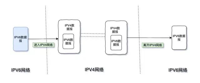
- “Tunneling Technology”: What is tunneling technology? It can be understood literally. Let’s illustrate it with a diagram. Tunneling technology essentially means that data undergoes another layer of encapsulation and decapsulation during transmission. For example, data enters the IPv4 network encapsulated in IPv6 packets.
Transport Layer
Stop-and-Wait Protocol
What is the stop-and-wait protocol? You might understand it better after looking at the diagram below:
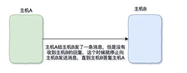
The stop-and-wait protocol consists of the following three parts:
- “No Error Situation”: As shown in the above diagram, to ensure error-free transmission, host A must continue to send messages to host B until it receives a reply from host B.
- “Error Occurrence”: If an error occurs, such as host A not receiving a reply from host B, a mechanism will trigger host A to resend the message to host B. This involves choosing a “Retransmission Time”; this retransmission time should not be less than RTT (the time taken for host A to send a message to host B and for host B to send a reply back to host A).
- “Acknowledgment Loss and Acknowledgment Delay”: For acknowledgment delays and losses, see the diagram below for clarity:
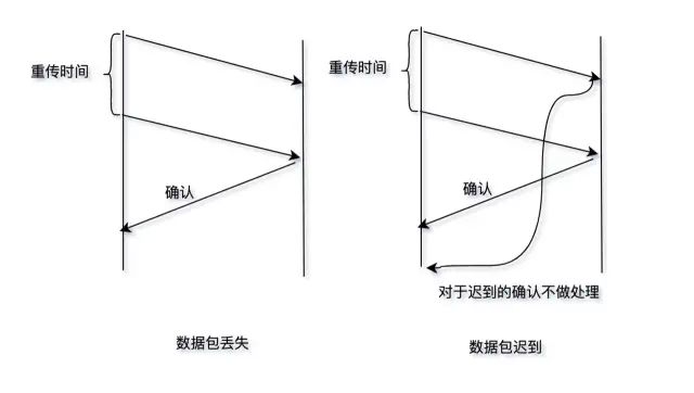
During transmission, data may be lost or delayed. Lost data will be retransmitted, while delayed data will not be processed. Since we are discussing the stop-and-wait protocol, I must also mention the ARQ protocol. What is the ARQ protocol?
The ARQ protocol allows the sender to send multiple packets without waiting for acknowledgment of the previous message, thus improving channel utilization and enabling sufficient data to be transmitted within a certain period.
UDP
UDP protocol is relatively simple compared to TCP protocol, and the focus of the transport layer is naturally the TCP protocol. Below, let’s briefly explain the UDP protocol.
“UDP has the following characteristics:”
- Connectionless protocol, performing unreliable transmission
- Datagram-oriented
- No congestion control
- Small overhead for UDP datagram headers
- Supports one-to-one, one-to-many, many-to-one, and many-to-many data transmissions
TCP
Overview of TCP
“TCP is another protocol at the transport layer and has the following characteristics:”
- TCP is a connection-oriented transport layer protocol
- Provides reliable delivery
- Uses full-duplex communication
- Byte stream-oriented
TCP Datagram
See the image below (image source from the Internet).
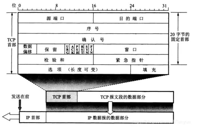
Here, I will explain some fields of the datagram:
- “Source Port”: The port number of the sending host
- “Destination Port”: The port number of the receiving host
- “Sequence Number”: Each byte in the byte stream transmitted in a TCP connection is numbered sequentially. The starting sequence number must be set when the connection is established. The sequence number field in the TCP datagram indicates the sequence number of the first byte of data being sent in this segment.
- “Acknowledgment Number”: The sequence number of the first data byte the sender expects to receive in the next segment. If the acknowledgment number is N, it indicates that all data up to sequence number N-1 has been correctly received.
- “Data Offset”: Indicates how far the data starts from the beginning of the TCP datagram.
- “Window”: The window field specifies the amount of data the sender allows the receiver to send. The window value often changes dynamically. The window refers to the receiving window of the party sending this datagram (not its own sending window).
- “Checksum”: The checksum field checks both the header and the data. When calculating the checksum, a pseudo-header of 12 bytes is added to the front of the TCP datagram (as with UDP).
- “ACK”: The acknowledgment number field is only valid when ACK=1. When ACK=0, the acknowledgment number is invalid. TCP stipulates that all transmitted segments must have ACK set to 1 after the connection is established.
- “Push”: When two application processes are interacting, sometimes one end wants to receive the other’s response immediately after typing a command, rather than waiting for the entire buffer to fill up before delivering. In this case, the sending TCP sets PSH to 1 and immediately creates a segment to send. The receiving TCP, upon receiving a segment with PSH=1, delivers it as quickly as possible to the receiving application process.
- “Reset”: When RST=1, it indicates that a serious error has occurred in the TCP connection (such as due to a host crash or other reasons), necessitating the release of the connection and re-establishing the transport connection.
- “SYN”: Used to synchronize sequence numbers during connection establishment. When SYN=1 and ACK=0, it indicates a connection request segment.
- “FIN”: Used to release a connection.
Sliding Window
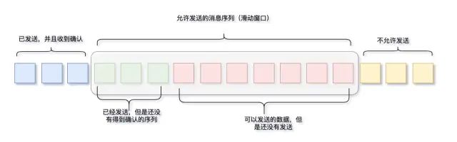
To improve the efficiency of data transmission, TCP uses a mechanism called the sliding window for data sending.
Below is a diagram of the sliding window at the sending end, where the size of the sliding window is the length of the green and red sections. Its working mechanism is that once the sender receives an acknowledgment, the sliding window moves to the right.
Flow Control
<pflow a="" be="" can="" control="" in="" p="" sentence.
❝
The receiving end provides negative feedback to the sending end, which can control the size of the sliding window at the sending end.
❞
Next, let’s see how it’s described on Zhihu; I found an explanation that is the most illustrative and can help with understanding.

Congestion Control
- “Slow Start:” Slow start means that when a TCP link is first established, it should not send a large amount of data at once, leading to a sudden increase in network congestion, but instead gradually increase the congestion window based on feedback.
- “Congestion Avoidance:” Congestion avoidance means that the sliding window increases slowly rather than exponentially as in slow start.
- “Fast Retransmit:” The sender should immediately retransmit any segments that have not been received upon receiving three duplicate acknowledgments, without waiting for the configured retransmission timer to expire.
- “Fast Recovery:” Fast recovery has the following two characteristics:
- When the sender receives three consecutive duplicate acknowledgments, it executes the “multiplicative decrease” algorithm, halving the slow start threshold. This is to prevent network congestion. Note that the slow start algorithm is not executed next.
- When executing the fast recovery algorithm, the sliding window value is adjusted, and then the congestion avoidance algorithm is executed, gradually increasing the congestion window.
Three-Way Handshake
The three-way handshake and the four-way handshake are common topics in interviews, but before introducing the three-way handshake, it is necessary to understand the “Commonalities of Ideal Transmission Conditions”:
- The transmission channel does not generate errors
- No matter how fast the sender transmits data, the receiver can always receive the data in a timely manner.
Ideal conditions are ultimately ideal. The above two situations cannot occur in actual environments. Therefore, we will discuss how to make our actual situations closer to ideal, which is what we will talk about next: the three-way handshake.
First, both the three-way handshake and the four-way handshake are for TCP; UDP is a connectionless protocol and cannot have three-way handshakes or four-way handshakes. The three-way handshake and four-way handshake are designed to ensure reliable transmission. Let’s first look at the process diagram of the three-way handshake.
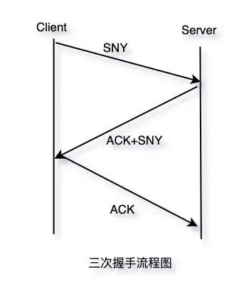
Since it is intended for reliable transmission, it is essential to ensure the normal sending and receiving of data between the client and server.
- “First Handshake”: The Client cannot confirm anything; the Server confirms that the Client has sent correctly.
- “Second Handshake”: The Client confirms: it can send and receive correctly, and the other party can send and receive correctly; the Server confirms: it can receive correctly, and the Client can send correctly.
- “Third Handshake”: The Client confirms: it can send and receive correctly, and the other party can send and receive correctly; the Server confirms: it can send and receive correctly, and the other party can send and receive correctly.
Why is the third handshake necessary? In one sentence, it mainly prevents outdated connection request messages from suddenly being sent to the server, which could lead to errors.
Through the above three steps, the Client and Server can achieve reliable transmission, and none can be omitted.
Four-Way Handshake
Since we understood the three-way handshake, the four-way handshake should pose no difficulty. Let’s first attach the process diagram.
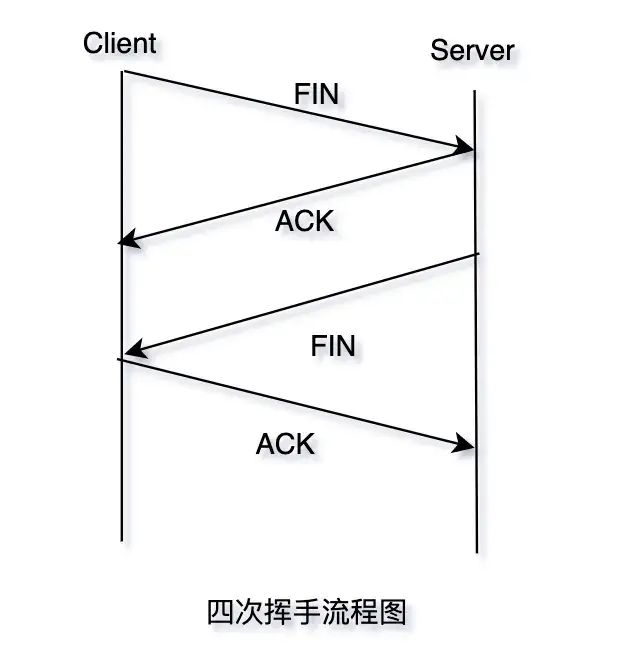
Like the three-way handshake, the four-way handshake is also aimed at ensuring reliable transmission. The four-way handshake is the process of disconnecting the connection between the Client and the Server. You might wonder why it takes four steps to disconnect the connection when three steps are sufficient to establish one. Can’t it be done in one or two steps?
Actually, since both the sending and receiving parties need to confirm, the four-way handshake also requires confirmation from both the sending and receiving parties.
- “First Handshake”: The Client sends a request to the Server to disconnect the connection.
- “Second Handshake”: The Server sends a confirmation of the disconnection to the Client. After receiving this, the TCP enters a half-connection state, and the channel from the Client to the Server for sending data is closed.
- “Third Handshake”: The Server sends a request to the Client to disconnect the connection.
- “Fourth Handshake”: The Client sends a confirmation of the disconnection to the Server. After receiving this, the TCP connection is completely terminated.
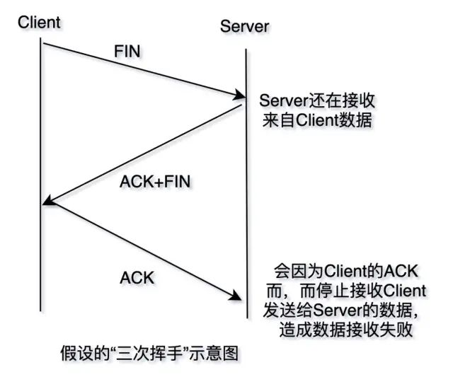
One can also consider the aforementioned issue. If during the second handshake, the Server sends an ACK while simultaneously sending a FIN request to the Client, and if the Server is still receiving data from the Client, it would close the receiving data channel due to the next ACK from the Client, resulting in a failure to receive the data, as illustrated in the diagram below.
Here’s a recommended article to help everyone better understand the establishment and disconnection processes of TCP connections: Two Animated Diagrams to Thoroughly Understand TCP’s Three-Way Handshake and Four-Way Handshake.
Application Scenarios for TCP and UDP
Regarding the relationship between TCP and UDP, you might understand it better after looking at the diagram below (image source from the Internet):
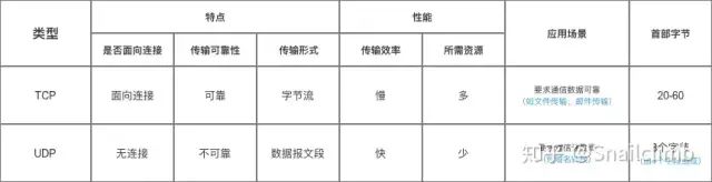
TCP is reliable transmission, while UDP is unreliable transmission. So why do we still need to use unreliable UDP for data transmission?
We know that UDP does not need to establish a connection before transmitting data, and the remote host does not need to acknowledge the receipt of UDP packets. Although UDP does not provide reliable delivery, in some cases, UDP is indeed the most effective way to work (generally used for real-time communication), such as: QQ voice, QQ video, live streaming, etc.
TCP provides connection-oriented services. A connection must be established before data can be transmitted, and the connection must be released after data transmission to save system resources. TCP does not provide broadcast or multicast services. Since TCP aims to provide reliable, connection-oriented transport services (the reliability of TCP is reflected in the fact that before data transmission, there will be a three-way handshake to establish a connection, and during data transmission, there are acknowledgment, window, retransmission, and congestion control mechanisms, and after data is transmitted, the connection is also released to save system resources), this inevitably increases many overheads, such as acknowledgment, flow control, timers, and connection management. This not only enlarges the header of the protocol data unit but also occupies many processor resources. TCP is generally used in scenarios such as file transfer, sending and receiving emails, remote login, etc.
Application Layer
HTTP Protocol
Regarding the definition of HTTP, let’s see what Wikipedia says:
❝
HTTP is a standard for requests and responses between a client (user) and a server (website), typically using the TCP protocol. By using web browsers, web crawlers, or other tools, the client sends an HTTP request to the server on a specified port (default port is 80). This client is called a user agent. The responding server stores some resources, such as HTML files and images. We call this responding server the origin server.
❞
HTTP protocol is now widely used on the World Wide Web. We will discuss HTTP in a separate article later, but for now, we need to talk about HTTPS.
Actually, HTTP and HTTPS are the same protocol, except that HTTPS is encapsulated with SSL (Secure Socket Layer) or TLS (Transport Layer Security). From these two protocols, we can see that HTTPS is secure, while HTTP is not secure.
FTP Protocol
FTP (File Transfer Protocol) is an application layer protocol that operates on top of the TCP/IP protocol suite and is a reliable transmission protocol. Its main function is to facilitate file distribution and sharing among users, as well as to be used by network administrators for tasks such as device version upgrades, log downloads, and configuration saving.
DNS Protocol
Earlier, we mentioned that IP addresses are used to locate hosts, but in real life, it is challenging to remember these arbitrary IP addresses; we only know the domain names of websites. So what should we do?
Thus, the DNS protocol emerged.
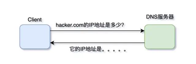
DNS is the Domain Name System; if we know the domain name but not the IP address of the server, we need to use the DNS protocol.
DHCP Protocol
What is the DHCP protocol? Let’s look at the definition on Wikipedia:
❝
Dynamic Host Configuration Protocol (DHCP) is a communication protocol that enables network administrators to centrally manage and automatically allocate IP network addresses. In an IP network, each device connected to the Internet requires a unique IP address. DHCP allows network administrators to monitor and allocate IP addresses from a central point. When a computer moves to another location within the network, it can automatically receive a new IP address.
❞
Wikipedia has explained it very clearly; the function of DHCP is to dynamically assign IP addresses to hosts, significantly reducing the workload of network administrators.
Source | 22j.co/cPaX
-
The interviewer asks: What to do when the auto-increment ID of MySQL runs out?
-
After inserting 10 million records into ArrayList, I doubted the JVM…
-
The second interview at Ant Group, the interviewer asked me about the implementation principle of zero-copy, and I was stunned…
Recently, I interviewed at BAT and organized an interview material titled "Java Interview BAT Pass Manual," covering Java core technologies, JVM, Java concurrency, SSM, microservices, databases, data structures, etc. The way to obtain it: click "Like," follow the public account, and reply with 666 to receive it. More content will be released gradually.See you tomorrow (。・ω・。)ノ♡