Background
The I2S bus is a common bus that needs to be mastered.
Concepts
The I2S (Inter-IC Sound) bus, also known as the integrated circuit built-in audio bus, is a bus standard formulated by Philips for audio data transmission between digital audio devices. This bus is responsible for data transmission between audio devices and is widely used in various multimedia systems. It employs a design that transmits clock and data signals along separate wires, avoiding distortion caused by timing differences and saving users the cost of purchasing specialized equipment to resist audio jitter.
I2S Bus Specifications
I2S has four lines, including: IISDI (serial data input), IISDO (serial data output), IISLRCK (left-right channel selection), and SCLK (serial bit clock).
The devices generating
IISLRCKandIISCLKare the master devices.
I2S has three main signals: 1. Serial clock SCLK, also called bit clock (BCLK), corresponds to each bit of digital audio data, with one pulse for each SCLK. The frequency of SCLK = 2 × sampling frequency × sampling bit count.
-
Frame clock LRCK (also known as WS) is used to switch the data of the left and right channels. LRCK being “1” indicates that the data being transmitted is for the right channel, while “0” indicates that the data is for the left channel. The frequency of LRCK equals the sampling frequency.
3. Serial data SDATA, which represents audio data in binary two’s complement. (MSB —> LSB: data is transmitted from high bit to low bit)
4. Generally, there is also MCLK, the master clock, also known as the system clock (Sys Clock), which is 256 or 384 times the sampling frequency.
Sometimes, to better synchronize between systems, an additional signal MCLK, called the master clock, needs to be transmitted.
No matter how many bits of valid data an I2S formatted signal has, the highest bit of the data always appears at the second SCLK pulse after the LRCK changes (which indicates the start of a frame).
This allows the number of valid bits at the receiving end to differ from that at the sending end (because there is a fixed format, it is known how to retain or expand).
If the number of valid bits that the receiving end can handle is less than that of the sending end, it can discard the excess low bits from the data frame;
If the number of valid bits that the receiving end can handle is more than that of the sending end, it can fill in the remaining bits itself.
This synchronization mechanism makes interconnection between digital audio devices more convenient without causing data misalignment.
No matter how many bits of valid data an I2S formatted signal has, the highest bit (MSB) of the data is always transmitted first, and the amount of data that can be sent at one time is determined by the effective bit count of the I2S format.
Features of I2S
1. Supports full duplex/half duplex
2. Supports master/slave mode
3. Compared to PCM, I2S is more suitable for stereo systems. Of course, variants of I2S also support multi-channel time-division multiplexing, thus supporting multi-channel audio.
Various Standards of I2S
With the development of technology, various data formats have emerged under a unified I2S hardware interface, which can be divided into left-aligned (MSB) standard, right-aligned (LSB) standard, and I2S Philips standard. The I2S supported by STM32 is a 3-pin synchronous serial interface communication protocol. It supports four audio standards, including the Philips I2S standard, MSB and LSB aligned standards, and PCM standard. It can operate in both master and slave modes in half-duplex communication. When it acts as the master device, it provides clock signals to external slave devices through the interface.
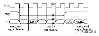
1) I2S Philips Standard
Uses the WS signal to indicate the channel to which the currently sent data belongs; when it is 0, it indicates left channel data. This signal becomes valid from one clock before the first bit (MSB) of the current channel data. The sender changes the data on the falling edge of the clock signal (CK), while the receiver reads the data on the rising edge. The WS signal also changes on the falling edge of SCK. Refer to Figure 383 for the 24-bit data encapsulated in a 32-bit frame transmission waveform. As mentioned earlier, the frequency of the WS line corresponds to the sampling frequency FS; one WS line cycle includes sending left and right channel data, and 64 CK cycles are actually needed to complete one transmission.
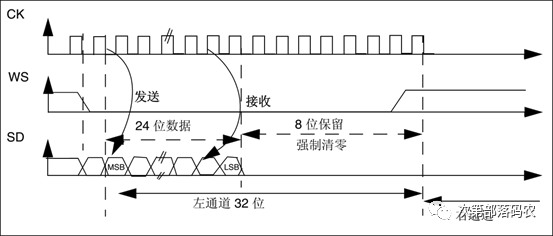
I2S Philips Standard 24-bit Transmission
2) Left-Aligned Standard
Data transmission begins simultaneously with the WS flip; refer to Figure 384 for the 24-bit data encapsulated in a 32-bit frame transmission waveform. This standard is used less frequently. Note that when WS is 1, the data being transmitted is for the left channel, which is exactly the opposite of the I2S Philips standard.
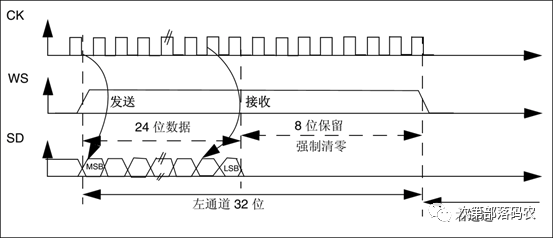
Left-Aligned Standard 24-bit Transmission
3) Right-Aligned Standard
Similar to the left-aligned standard; refer to Figure 385 for the 24-bit data encapsulated in a 32-bit frame transmission waveform.
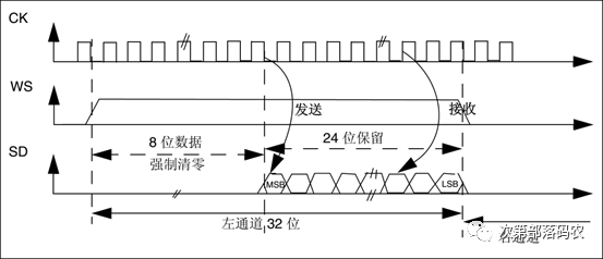
Right-Aligned Standard 24-bit Transmission
4) PCM Standard
PCM, or Pulse Code Modulation, is the result of sampling, quantizing, and arranging analog voice signals. WS no longer serves as a channel data selector. It has two modes: short frame mode and long frame mode, determined by the high-level holding time of the WS signal. Long frame mode holds for 13 CK cycles, while short frame mode holds for only 1 CK cycle, selectable via related register bits. If multi-channel data is transmitted within one WS cycle, the right channel data follows immediately after the left channel data is sent. Figure 386 shows the waveform for sending mono data expanded from 16-bit to 32-bit data frame.
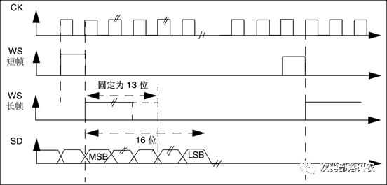
PCM Standard 16-bit Transmission