Development Trends: Flat Wire, Oil Cooling, Multi-in-One
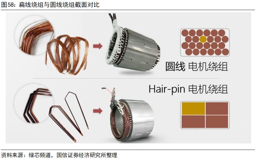
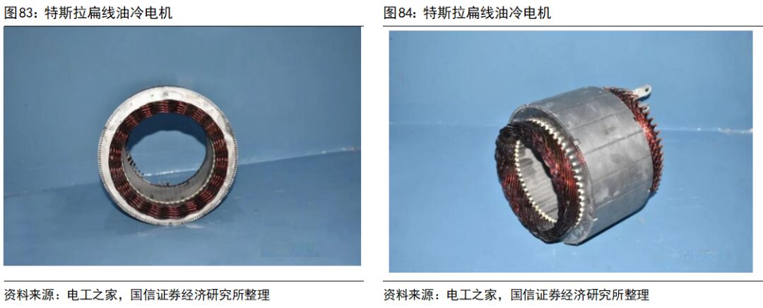
The flat wire motor refers to replacing the traditional cylindrical enameled copper wire in the stator winding with flat wire processed into a hairpin shape. In the cross-section of the round wire motor’s stator, there are large gaps left between the round copper wires, while the rectangular copper wires in the flat wire motor’s stator cross-section can fill the space better, improving the slot fill factor. This is the fundamental difference between flat wire motors and round wire motors.
The flat wire motor can improve the bare copper slot fill rate by 20%-30% compared to the traditional round wire motor. An increase in slot fill rate means that the motor can output higher power and torque under the same volume conditions; or, under the same power conditions, the outer diameter and volume of the motor can be reduced, thereby reducing the weight of the motor. Therefore, flat wire winding motors have a higher power density, allowing permanent magnet motors to continue to develop towards miniaturization.
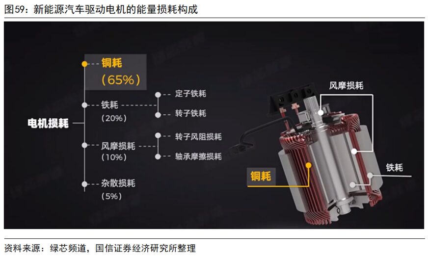
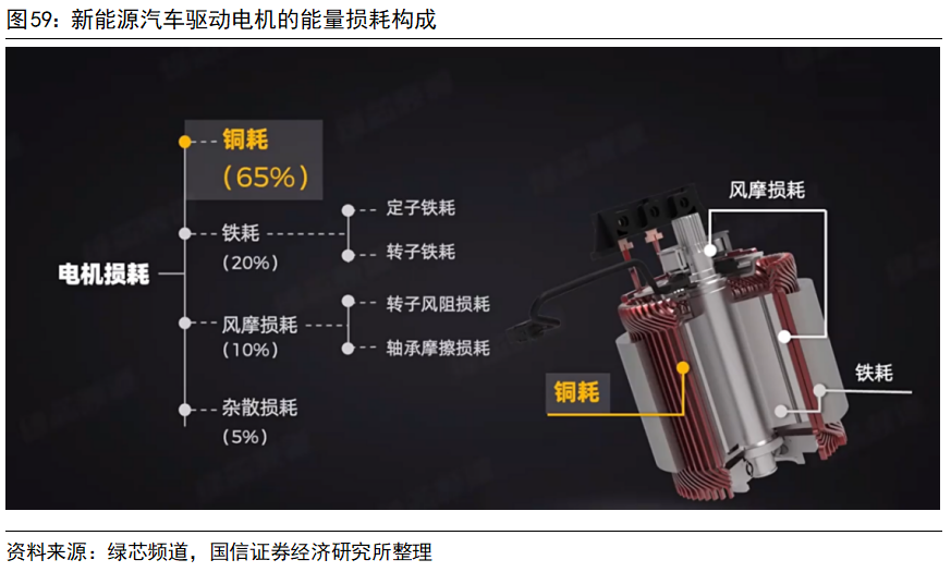
Compared to round wire motors, the primary advantage of flat wire motors is reduced losses and improved efficiency. In permanent magnet synchronous motors, copper losses (mainly losses in the stator winding) account for about 65%, iron losses (losses in the stator and rotor iron cores) account for about 20%, and other losses account for a relatively low proportion. The iron loss levels of flat wire motors and round wire motors are similar, with the main difference being in copper loss.Compared to traditional round wire motors, the bare copper slot fill rate of flat wire motors can be improved by 20%-30%, total copper loss is reduced by 21%, and efficiency increases by about 1%.
2. Oil Cooling Technology
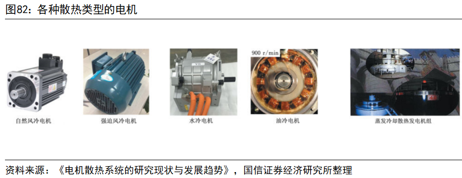
Air cooling, liquid cooling, and evaporative cooling systems are three common motor cooling systems. Air cooling systems have been widely used in small power motor cooling due to their low cost, high reliability, and ease of installation. Liquid cooling systems have high cooling power, with cooling efficiency reaching 50 times that of air cooling, suitable for scenarios with high heat generation and heat flow density. However, liquid cooling systems require additional circulation liquid paths and sealing systems, increasing the cost and complexity of the motor system. Evaporative cooling systems are mainly applied in megawatt-class large capacity generator sets, utilizing gas-liquid phase change cycles for efficient motor cooling.
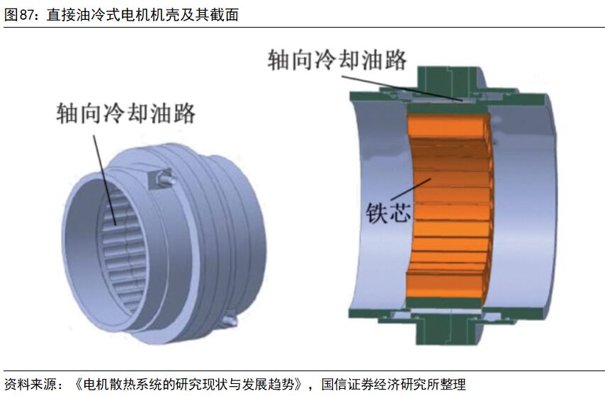
 The liquid cooling forms for automotive permanent magnet synchronous motors can be roughly divided into two types: direct cooling and indirect cooling. Indirect cooling is designed with cooling channels inside the casing, where the coolant flows through the entire casing to carry away heat. Direct cooling involves injecting cooling oil into the sealed motor, utilizing the high specific heat capacity of the cooling oil for cooling. Moreover, direct cooling can increase the contact area with the heat source, resulting in better cooling effects. Permanent magnet synchronous motors have significant heat generation at the winding ends; under water cooling, the coolant cannot directly contact the windings, but under oil cooling, the cooling oil can directly contact the windings, leading to higher cooling efficiency and more prominent advantages.
Under oil cooling technology, the cooling oil can directly contact the motor’s heat-generating components, and the cooling efficiency is far superior to traditional water cooling systems. Additionally, the oil medium has advantages such as good insulation, high dielectric constant, low freezing point, and high boiling point. The drive motor in BYD’s DMI system uses direct injection rotor oil cooling technology, which can increase the motor’s power density by 32%.
3. Multi-in-One Electric Drive System
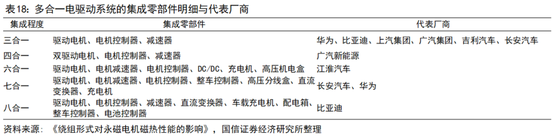
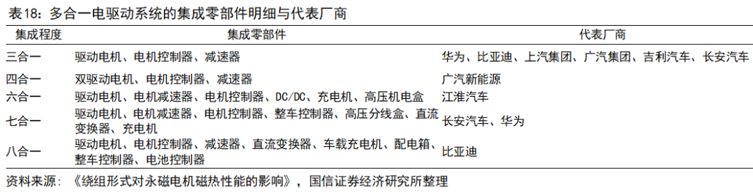
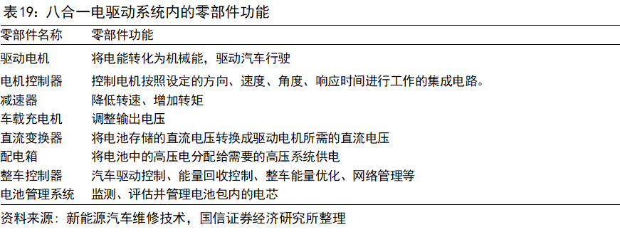
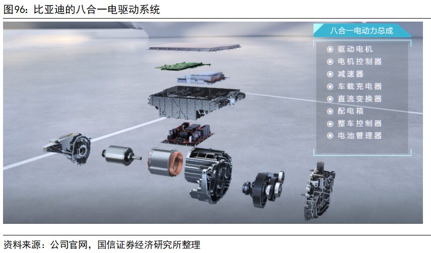
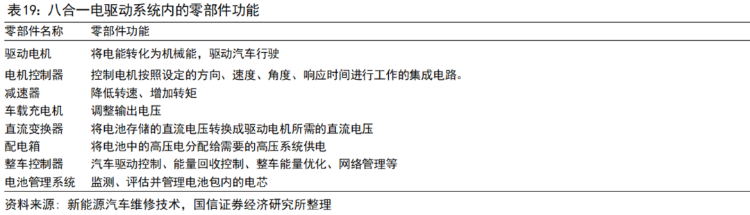
With the increasing requirements for range, power density, and energy utilization efficiency in new energy vehicles, electric drive systems are rapidly developing towards integration, miniaturization, and lightweight. Currently, multi-in-one electric drive systems have been released in three-in-one, four-in-one, six-in-one, seven-in-one, and even eight-in-one configurations, with the most common being the three-in-one electric drive system. Multi-in-one electric drive systems integrate components such as motors, reducers, and controllers, sharing parts like housings and wiring harnesses to achieve integration, cost reduction, and lightweight.
The liquid cooling forms for automotive permanent magnet synchronous motors can be roughly divided into two types: direct cooling and indirect cooling. Indirect cooling is designed with cooling channels inside the casing, where the coolant flows through the entire casing to carry away heat. Direct cooling involves injecting cooling oil into the sealed motor, utilizing the high specific heat capacity of the cooling oil for cooling. Moreover, direct cooling can increase the contact area with the heat source, resulting in better cooling effects. Permanent magnet synchronous motors have significant heat generation at the winding ends; under water cooling, the coolant cannot directly contact the windings, but under oil cooling, the cooling oil can directly contact the windings, leading to higher cooling efficiency and more prominent advantages.
Under oil cooling technology, the cooling oil can directly contact the motor’s heat-generating components, and the cooling efficiency is far superior to traditional water cooling systems. Additionally, the oil medium has advantages such as good insulation, high dielectric constant, low freezing point, and high boiling point. The drive motor in BYD’s DMI system uses direct injection rotor oil cooling technology, which can increase the motor’s power density by 32%.
3. Multi-in-One Electric Drive System
With the increasing requirements for range, power density, and energy utilization efficiency in new energy vehicles, electric drive systems are rapidly developing towards integration, miniaturization, and lightweight. Currently, multi-in-one electric drive systems have been released in three-in-one, four-in-one, six-in-one, seven-in-one, and even eight-in-one configurations, with the most common being the three-in-one electric drive system. Multi-in-one electric drive systems integrate components such as motors, reducers, and controllers, sharing parts like housings and wiring harnesses to achieve integration, cost reduction, and lightweight.
 Flat wire motors have larger gaps between flat copper wires, allowing cooling oil to penetrate easily, promoting the application of direct oil cooling technology. Additionally, the cooling oil has good insulation properties and can be reused in multiple scenarios, accelerating the integration process of the vehicle’s thermal management system and promoting the widespread adoption of multi-in-one electric drive system assemblies.
Performance Requirements: High Efficiency, Large Torque, Strong Cooling
New energy vehicle drive motors are a type of industrial motor, and their principles (electromagnetic induction), analytical methods (ordinary electromagnetic analysis methods), computational tools (finite element software), and electromagnetic equations (Maxwell’s equations) are consistent with those of ordinary industrial motors. The classification methods and control methods also do not have fundamental differences.However, due to the special environment of vehicles, the special performance requirements of new energy vehicle drive motors mainly manifest in high power density, wide speed range, high starting torque, broad efficiency range, and strong cooling needs.
1) High Power Density: Vehicle drive motors have strict volume, weight, and power requirements. Most industrial scenarios have ample space, with the primary goal being to meet industrial demands, and motor size limitations are not prominent. However, in new energy vehicles, the size and weight of the motor directly affect the vehicle’s dynamic performance and driving experience. The design direction and challenges for motors lie in being small in size, light in weight, and high in power, maximizing power-to-weight and power-to-volume density.
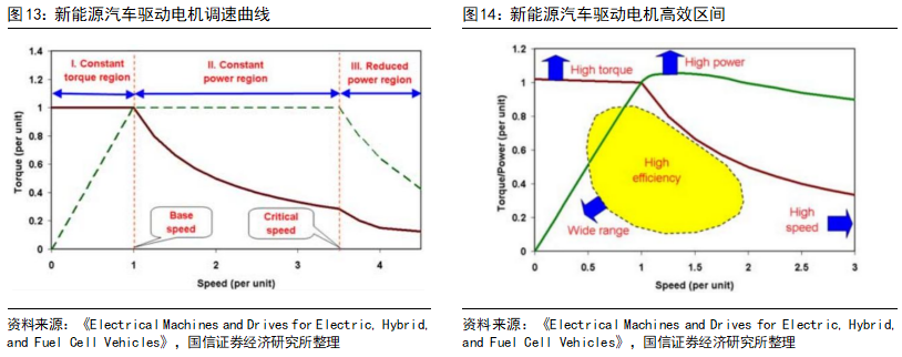
2) Wide Speed Range: A broad speed range can help new energy vehicles eliminate multi-speed gearboxes, using only fixed gear sets, effectively reducing costs. Therefore, the wider the speed range of new energy vehicle drive motors, the better, with maximum speeds exceeding four times the base speed. The basic version of Tesla Model S has a maximum motor speed of 18,000 RPM, while the motor of BYD’s E platform 3.0 exceeds 17,000 RPM.
3) High Starting Torque: As cars emphasize performance indicators such as acceleration, new energy vehicle drive motors require ultra-high torque at startup or low speeds, quickly elevating the vehicle’s speed to the desired level. General industrial motors do not have such high requirements for starting speeds.
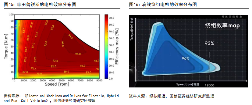
4) Broad Efficiency Range: New energy vehicles, especially pure electric vehicles, are powered by onboard battery packs rather than by overhead lines as in electric locomotives. Therefore, the efficiency of the motor directly affects the range, leading to high efficiency requirements for motors. The drive motors of new energy vehicles need to have as broad a high-efficiency operating range as possible. Under normal road conditions, cars do not frequently start or run at high speeds; rather, they mostly accelerate or decelerate while cruising at a constant speed, making the efficiency during the middle portion of operation particularly important.
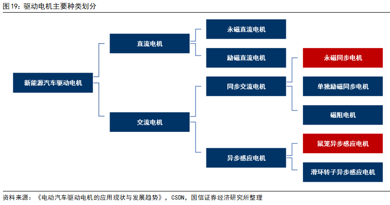
5) Strong Cooling Needs: Due to the high power density requirements of new energy vehicle drive motors, cooling issues arise. A traditional power system assembly with a peak power of 150KW has a volume of about 409L. In contrast, an electric vehicle power system assembly with a peak power of 150KW has a volume of only 82L, roughly 20% of the traditional power assembly’s volume. High power in a small volume leads to issues such as cooling, mechanical vibration, electromagnetic compatibility, and NVH (noise, vibration, and harshness). The energy conversion efficiency of motors is about 90% or more, with peak efficiency around 95%. The average energy loss is about 10%, and this 10% energy loss is mostly manifested in the form of heat, resulting in strong cooling demands for drive motors.
Technical Path: Permanent Magnet Synchronous Motors Account for 94%
Early new energy vehicle drive motors mostly used DC motors, partly due to the advantages of DC motors, such as simple control strategies, good speed performance, and low cost. On the other hand, the control technology of AC motors is complex and costly. The speed of DC motors is directly proportional to the voltage, making them easy to control; while the speed of AC motors is proportional to the frequency and the number of poles, requiring higher control technology.
However, DC motors have some inherent defects. With substantial advancements in AC motor technology, DC motors are currently on the verge of being phased out.
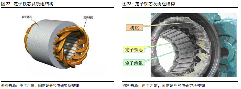
1) Brushed DC Motors: Brushes in brushed DC motors serve the function of current commutation. In actual use, brushes wear out quickly and often require maintenance, while the commutation spark limits the motor’s high-speed operation, posing threats to the motor’s stability and safety, making these issues difficult to overcome.
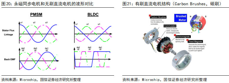
2) Brushless DC Motors: The voltage and current waveforms of brushless DC motors are rectangular or trapezoidal waves, accompanied by significant torque pulsations, leading to noticeable jolts during vehicle operation, negatively impacting user experience. In contrast, the waveforms of AC motors are typically sinusoidal, resulting in smoother torque and less vibration.
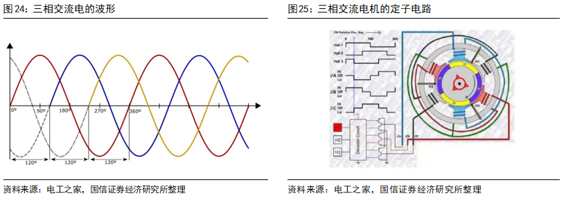
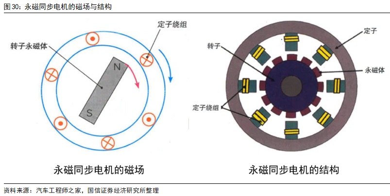
Three common types of AC motors are permanent magnet synchronous motors, induction asynchronous motors, and synchronous reluctance motors. The stators of AC motors are basically the same, with the main difference being in the rotors. The stator mainly consists of the iron core and coils; the stator iron core is made of laminated silicon steel sheets; the enameled wire is wound into coils, embedded in the stator slots, and then insulated; the insulated iron core is fitted into the casing to obtain the stator.
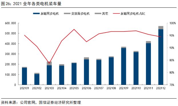
The stator winding connects to the AC power supply (usually three-phase AC), and when combined with coils that are 120° apart in space, their synthesized magnetic field acts like a uniformly strong magnetic field that rotates, pulling the rotor to rotate.
According to data from Gaogong Lithium Battery, in 2021, the cumulative installed capacity of permanent magnet synchronous motors/induction asynchronous motors/other motors was 323/17/2 million units, accounting for 94%/5%/1%, respectively. Permanent magnet synchronous motors dominate the domestic new energy vehicle drive motor market.
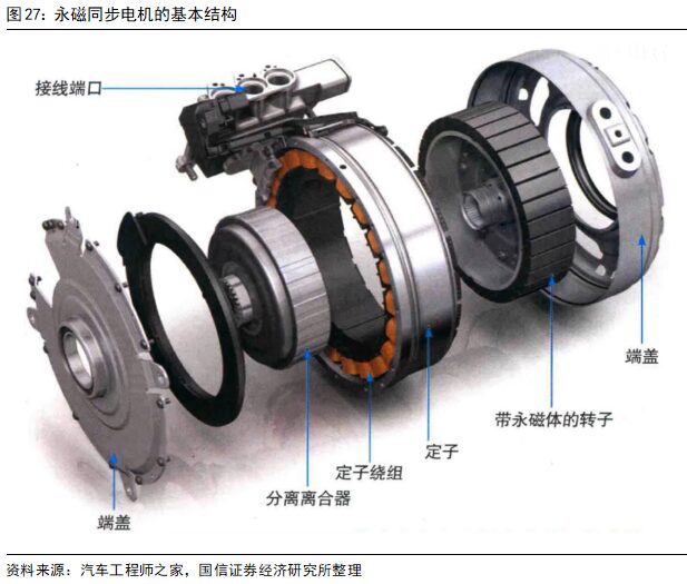
The rotor of a permanent magnet synchronous motor consists of an iron core, magnetic steel, and a shaft assembly, where the magnetic steel provides the magnetic flux for the motor and has the most significant impact on motor performance, typically made from rare earth neodymium-iron-boron through powder metallurgy.
Flat wire motors have larger gaps between flat copper wires, allowing cooling oil to penetrate easily, promoting the application of direct oil cooling technology. Additionally, the cooling oil has good insulation properties and can be reused in multiple scenarios, accelerating the integration process of the vehicle’s thermal management system and promoting the widespread adoption of multi-in-one electric drive system assemblies.
Performance Requirements: High Efficiency, Large Torque, Strong Cooling
New energy vehicle drive motors are a type of industrial motor, and their principles (electromagnetic induction), analytical methods (ordinary electromagnetic analysis methods), computational tools (finite element software), and electromagnetic equations (Maxwell’s equations) are consistent with those of ordinary industrial motors. The classification methods and control methods also do not have fundamental differences.However, due to the special environment of vehicles, the special performance requirements of new energy vehicle drive motors mainly manifest in high power density, wide speed range, high starting torque, broad efficiency range, and strong cooling needs.
1) High Power Density: Vehicle drive motors have strict volume, weight, and power requirements. Most industrial scenarios have ample space, with the primary goal being to meet industrial demands, and motor size limitations are not prominent. However, in new energy vehicles, the size and weight of the motor directly affect the vehicle’s dynamic performance and driving experience. The design direction and challenges for motors lie in being small in size, light in weight, and high in power, maximizing power-to-weight and power-to-volume density.
2) Wide Speed Range: A broad speed range can help new energy vehicles eliminate multi-speed gearboxes, using only fixed gear sets, effectively reducing costs. Therefore, the wider the speed range of new energy vehicle drive motors, the better, with maximum speeds exceeding four times the base speed. The basic version of Tesla Model S has a maximum motor speed of 18,000 RPM, while the motor of BYD’s E platform 3.0 exceeds 17,000 RPM.
3) High Starting Torque: As cars emphasize performance indicators such as acceleration, new energy vehicle drive motors require ultra-high torque at startup or low speeds, quickly elevating the vehicle’s speed to the desired level. General industrial motors do not have such high requirements for starting speeds.
4) Broad Efficiency Range: New energy vehicles, especially pure electric vehicles, are powered by onboard battery packs rather than by overhead lines as in electric locomotives. Therefore, the efficiency of the motor directly affects the range, leading to high efficiency requirements for motors. The drive motors of new energy vehicles need to have as broad a high-efficiency operating range as possible. Under normal road conditions, cars do not frequently start or run at high speeds; rather, they mostly accelerate or decelerate while cruising at a constant speed, making the efficiency during the middle portion of operation particularly important.
5) Strong Cooling Needs: Due to the high power density requirements of new energy vehicle drive motors, cooling issues arise. A traditional power system assembly with a peak power of 150KW has a volume of about 409L. In contrast, an electric vehicle power system assembly with a peak power of 150KW has a volume of only 82L, roughly 20% of the traditional power assembly’s volume. High power in a small volume leads to issues such as cooling, mechanical vibration, electromagnetic compatibility, and NVH (noise, vibration, and harshness). The energy conversion efficiency of motors is about 90% or more, with peak efficiency around 95%. The average energy loss is about 10%, and this 10% energy loss is mostly manifested in the form of heat, resulting in strong cooling demands for drive motors.
Technical Path: Permanent Magnet Synchronous Motors Account for 94%
Early new energy vehicle drive motors mostly used DC motors, partly due to the advantages of DC motors, such as simple control strategies, good speed performance, and low cost. On the other hand, the control technology of AC motors is complex and costly. The speed of DC motors is directly proportional to the voltage, making them easy to control; while the speed of AC motors is proportional to the frequency and the number of poles, requiring higher control technology.
However, DC motors have some inherent defects. With substantial advancements in AC motor technology, DC motors are currently on the verge of being phased out.
1) Brushed DC Motors: Brushes in brushed DC motors serve the function of current commutation. In actual use, brushes wear out quickly and often require maintenance, while the commutation spark limits the motor’s high-speed operation, posing threats to the motor’s stability and safety, making these issues difficult to overcome.
2) Brushless DC Motors: The voltage and current waveforms of brushless DC motors are rectangular or trapezoidal waves, accompanied by significant torque pulsations, leading to noticeable jolts during vehicle operation, negatively impacting user experience. In contrast, the waveforms of AC motors are typically sinusoidal, resulting in smoother torque and less vibration.
Three common types of AC motors are permanent magnet synchronous motors, induction asynchronous motors, and synchronous reluctance motors. The stators of AC motors are basically the same, with the main difference being in the rotors. The stator mainly consists of the iron core and coils; the stator iron core is made of laminated silicon steel sheets; the enameled wire is wound into coils, embedded in the stator slots, and then insulated; the insulated iron core is fitted into the casing to obtain the stator.
The stator winding connects to the AC power supply (usually three-phase AC), and when combined with coils that are 120° apart in space, their synthesized magnetic field acts like a uniformly strong magnetic field that rotates, pulling the rotor to rotate.
According to data from Gaogong Lithium Battery, in 2021, the cumulative installed capacity of permanent magnet synchronous motors/induction asynchronous motors/other motors was 323/17/2 million units, accounting for 94%/5%/1%, respectively. Permanent magnet synchronous motors dominate the domestic new energy vehicle drive motor market.
The rotor of a permanent magnet synchronous motor consists of an iron core, magnetic steel, and a shaft assembly, where the magnetic steel provides the magnetic flux for the motor and has the most significant impact on motor performance, typically made from rare earth neodymium-iron-boron through powder metallurgy.
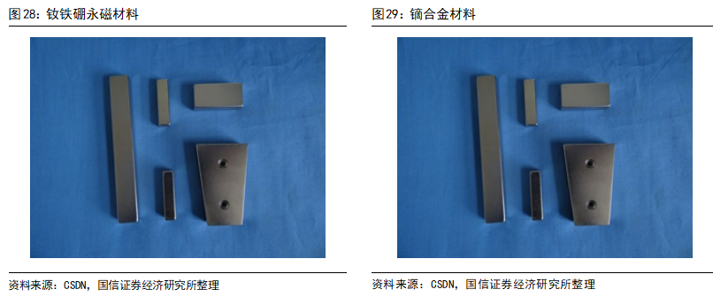
 In early motors, permanent magnet motors were very rare, primarily due to the lack of sufficiently strong permanent magnets. In 1982, Masato Sagawa of Sumitomo Special Metals discovered neodymium magnets. This type of magnet has a magnetic energy product greater than samarium-cobalt magnets, making it the material with the highest magnetic energy product in the world at that time. Later, Sumitomo Special Metals successfully developed powder metallurgy methods, and General Motors successfully developed the spray melting method, enabling the preparation of neodymium-iron-boron magnets. This type of magnet is the second most magnetic permanent magnet after absolute zero holmium magnets and is also the most commonly used rare earth magnet. Its advantages include high anti-demagnetization properties and cost-effectiveness; however, its disadvantages include strong temperature dependence and weak corrosion resistance, necessitating appropriate coatings or electroplating. To improve the temperature resistance and coercivity of neodymium-iron-boron, magnet manufacturers often add dysprosium to the formula, further increasing manufacturing costs.
 The rotor speed of a permanent magnet synchronous motor is synchronized with the speed of the stator magnetic field. Its workflow is that the stator winding is connected to AC power, generating a rotating magnetic field in the stator, and the rotor’s magnetic field, induced by the stator’s rotating magnetic field, follows the rotation, resulting in motor rotation and power output.
The main advantages of permanent magnet synchronous motors are high power density, high operating efficiency, simple and compact structure, large and smooth torque, and good speed control performance.
1) High Power Density: The neodymium-iron-boron magnetic material in permanent magnet synchronous motors has excellent magnetic performance. After magnetization, it does not require additional external energy to construct a strong magnetic field, and the magnetic field has permanent characteristics, eliminating the need for additional circuits for excitation (i.e., energizing conductors to create a magnetic field), maintaining a smaller volume and lighter weight. At rated power, under the same cooling conditions and insulation materials, the power density of permanent magnet synchronous motors is usually more than twice that of induction asynchronous motors.
2) High Operating Efficiency: Thanks to the permanent magnets in the rotor, the rotor of permanent magnet synchronous motors typically does not need to be energized (except for some self-starting conditions or eddy current losses), which reduces related energy losses and results in higher efficiency.
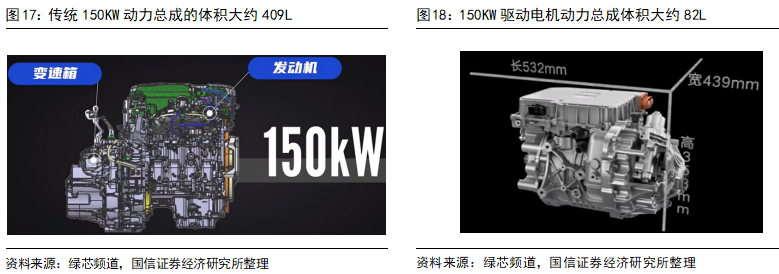
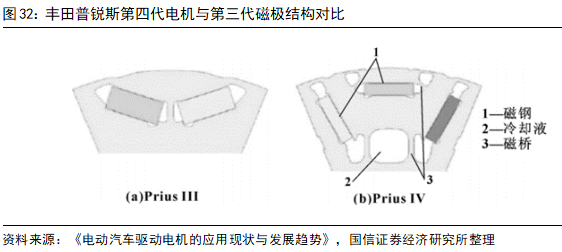
3) Simple and Compact Structure: Permanent magnet synchronous drive motors do not have excitation power supply structures or excitation winding structures, reducing structural complexity. The related components are relatively compact, ensuring that permanent magnet synchronous drive motors operate more reliably. The fourth-generation permanent magnet synchronous motor in the Toyota Prius has a 20% reduction in stator diameter compared to the third generation, resulting in a more compact overall structure and smaller volume.
4) Large and Smooth Torque: Within the rated current range, increasing the current can quickly enhance the torque of permanent magnet synchronous motors. Additionally, the rotating magnetic field formed by three-phase AC in the stator is also relatively stable, resulting in smaller torque pulsations. Especially in low-speed high-torque conditions (corresponding to the starting acceleration phase of new energy vehicles), permanent magnet synchronous motors have outstanding advantages compared to asynchronous induction motors.
5) Good Speed Control Performance: The relationship between electricity, magnetism, and force in permanent magnet synchronous motors is simpler than in induction asynchronous motors, making speed control easier. The state equation of asynchronous motors is fourth-order, with coupling between the rotor and stator equations (the current in the rotor is generated by the rotating stator magnetic field); the state equation of permanent magnet synchronous motors is second-order, with the magnetic field of the permanent magnet existing independently, making control much easier at both low and high speeds (above rated speed) compared to induction asynchronous motors.
The main disadvantages of permanent magnet synchronous motors are issues related to weak magnetic control, back electromotive force, demagnetization in high-temperature vibration environments, self-starting issues, and cost issues.
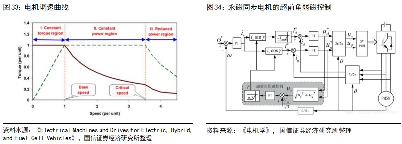
1) Weak Magnetic Control Issues: According to the basic winding voltage formula, since the voltage V that the power supply can provide is limited, when the motor’s speed reaches a certain level, additional speed increases require weak magnetic control to reduce inductance. This process is reflected in the motor’s speed curve as it transitions from the constant torque region to the constant power region. Since the rotor magnetic field of permanent magnet synchronous motors is provided by the permanent magnet, weak magnetic control requires consuming extra current to counteract part of the rotor magnetic field, reducing the operating efficiency under high-speed conditions and placing additional burdens on the power supply and inverter.
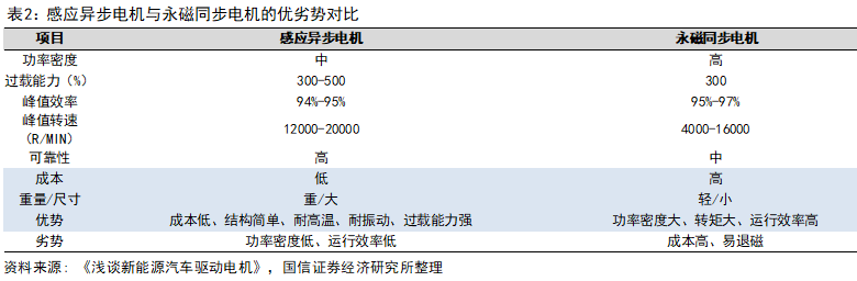
2) Back Electromotive Force Issues: When the rotor of a permanent magnet synchronous motor rotates at high speeds, the stator coil cuts the magnetic field lines of the rotor’s permanent magnets, generating an induced electromotive force. This induced electromotive force opposes the direction of the original coil voltage, hence the term back electromotive force. Back electromotive force offsets the input drive voltage of the stator, requiring higher input voltages to drive the motor at high speeds, which can lead to greater eddy current losses and high temperatures, damaging the stator coil and rotor permanent magnets. The faster the speed, the lower the efficiency. At high speeds, permanent magnet synchronous motors increasingly resemble generators.
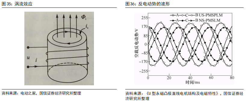
3) Demagnetization Issues in High-Temperature Vibration Environments: Commonly used neodymium-iron-boron permanent magnets, while excellent in performance, are prone to demagnetization in high temperatures, vibrations, and strong external magnetic fields. In addition to the heat generated by the energized stator winding, the rotor of permanent magnet synchronous motors, although not energized, still generates heat due to centrifugal forces, eddy current losses, and other factors.
The eddy current loss refers to the energy loss caused by induced currents within a conductor moving in a non-uniform magnetic field or situated in a time-varying magnetic field. The rotor speed of permanent magnet synchronous motors theoretically matches the speed of the stator magnetic field; however, due to the existence of stator teeth, the spatial distribution of windings, and the fact that the currents in three-phase windings are not standard sinusoidal waves, these factors lead to distortion in the internal magnetic field, resulting in high harmonic content in the air gap magnetic field, causing eddy currents in the motor’s iron core and permanent magnets, resulting in significant eddy current losses. At high speeds, the working frequency is high, and the rotor’s eddy current losses lead to more severe temperature issues.
The rotor speed of a permanent magnet synchronous motor is synchronized with the speed of the stator magnetic field. Its workflow is that the stator winding is connected to AC power, generating a rotating magnetic field in the stator, and the rotor’s magnetic field, induced by the stator’s rotating magnetic field, follows the rotation, resulting in motor rotation and power output.
The main advantages of permanent magnet synchronous motors are high power density, high operating efficiency, simple and compact structure, large and smooth torque, and good speed control performance.
1) High Power Density: The neodymium-iron-boron magnetic material in permanent magnet synchronous motors has excellent magnetic performance. After magnetization, it does not require additional external energy to construct a strong magnetic field, and the magnetic field has permanent characteristics, eliminating the need for additional circuits for excitation (i.e., energizing conductors to create a magnetic field), maintaining a smaller volume and lighter weight. At rated power, under the same cooling conditions and insulation materials, the power density of permanent magnet synchronous motors is usually more than twice that of induction asynchronous motors.
2) High Operating Efficiency: Thanks to the permanent magnets in the rotor, the rotor of permanent magnet synchronous motors typically does not need to be energized (except for some self-starting conditions or eddy current losses), which reduces related energy losses and results in higher efficiency.
3) Simple and Compact Structure: Permanent magnet synchronous drive motors do not have excitation power supply structures or excitation winding structures, reducing structural complexity. The related components are relatively compact, ensuring that permanent magnet synchronous drive motors operate more reliably. The fourth-generation permanent magnet synchronous motor in the Toyota Prius has a 20% reduction in stator diameter compared to the third generation, resulting in a more compact overall structure and smaller volume.
4) Large and Smooth Torque: Within the rated current range, increasing the current can quickly enhance the torque of permanent magnet synchronous motors. Additionally, the rotating magnetic field formed by three-phase AC in the stator is also relatively stable, resulting in smaller torque pulsations. Especially in low-speed high-torque conditions (corresponding to the starting acceleration phase of new energy vehicles), permanent magnet synchronous motors have outstanding advantages compared to asynchronous induction motors.
5) Good Speed Control Performance: The relationship between electricity, magnetism, and force in permanent magnet synchronous motors is simpler than in induction asynchronous motors, making speed control easier. The state equation of asynchronous motors is fourth-order, with coupling between the rotor and stator equations (the current in the rotor is generated by the rotating stator magnetic field); the state equation of permanent magnet synchronous motors is second-order, with the magnetic field of the permanent magnet existing independently, making control much easier at both low and high speeds (above rated speed) compared to induction asynchronous motors.
The main disadvantages of permanent magnet synchronous motors are issues related to weak magnetic control, back electromotive force, demagnetization in high-temperature vibration environments, self-starting issues, and cost issues.
1) Weak Magnetic Control Issues: According to the basic winding voltage formula, since the voltage V that the power supply can provide is limited, when the motor’s speed reaches a certain level, additional speed increases require weak magnetic control to reduce inductance. This process is reflected in the motor’s speed curve as it transitions from the constant torque region to the constant power region. Since the rotor magnetic field of permanent magnet synchronous motors is provided by the permanent magnet, weak magnetic control requires consuming extra current to counteract part of the rotor magnetic field, reducing the operating efficiency under high-speed conditions and placing additional burdens on the power supply and inverter.
2) Back Electromotive Force Issues: When the rotor of a permanent magnet synchronous motor rotates at high speeds, the stator coil cuts the magnetic field lines of the rotor’s permanent magnets, generating an induced electromotive force. This induced electromotive force opposes the direction of the original coil voltage, hence the term back electromotive force. Back electromotive force offsets the input drive voltage of the stator, requiring higher input voltages to drive the motor at high speeds, which can lead to greater eddy current losses and high temperatures, damaging the stator coil and rotor permanent magnets. The faster the speed, the lower the efficiency. At high speeds, permanent magnet synchronous motors increasingly resemble generators.
3) Demagnetization Issues in High-Temperature Vibration Environments: Commonly used neodymium-iron-boron permanent magnets, while excellent in performance, are prone to demagnetization in high temperatures, vibrations, and strong external magnetic fields. In addition to the heat generated by the energized stator winding, the rotor of permanent magnet synchronous motors, although not energized, still generates heat due to centrifugal forces, eddy current losses, and other factors.
The eddy current loss refers to the energy loss caused by induced currents within a conductor moving in a non-uniform magnetic field or situated in a time-varying magnetic field. The rotor speed of permanent magnet synchronous motors theoretically matches the speed of the stator magnetic field; however, due to the existence of stator teeth, the spatial distribution of windings, and the fact that the currents in three-phase windings are not standard sinusoidal waves, these factors lead to distortion in the internal magnetic field, resulting in high harmonic content in the air gap magnetic field, causing eddy currents in the motor’s iron core and permanent magnets, resulting in significant eddy current losses. At high speeds, the working frequency is high, and the rotor’s eddy current losses lead to more severe temperature issues.
 In summary, the above three issues of permanent magnet synchronous motors—weak magnetic control issues, back electromotive force issues, and demagnetization issues in high-temperature vibration environments—are limitations in high-speed conditions. These factors explain why electric vehicles equipped with permanent magnet synchronous motors often excel in zero-to-hundred acceleration performance but show weak secondary acceleration under high-speed cruising conditions and have limited peak speeds, making it difficult to sustain high-speed cruising.
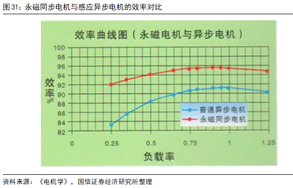
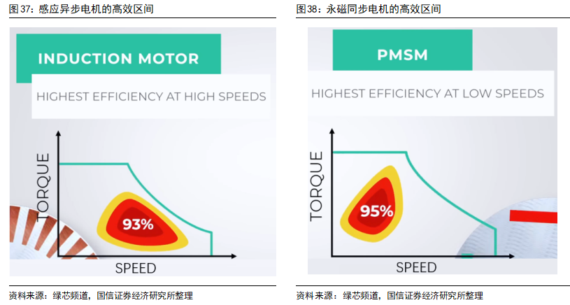
Comparing the efficiency graphs of permanent magnet synchronous motors and induction motors, we can clearly see that the peak efficiency of permanent magnet synchronous motors is higher than that of induction asynchronous motors, but the high-efficiency range is more concentrated in relatively low-speed areas, while the high-efficiency range of induction asynchronous motors extends more into the high-speed region.
4) Self-Starting Issues: Once the power supply is connected, the rotating magnetic field is immediately generated and rotates at high speed. The rotor, due to inertia, cannot follow immediately. As the stator magnetic poles repeatedly pass the rotor magnetic poles, the magnetic forces acting on the rotor magnetic poles are equal in magnitude but opposite in direction, resulting in zero average torque due to the very short time interval. Therefore, permanent magnet synchronous motors cannot self-start. Solving the self-starting issue requires additional configuration of an inverter (external frequency conversion, slow speed increase) or incorporating a squirrel cage structure from an induction motor into the rotor.
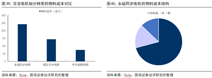
5) Cost Issues: The rotor of permanent magnet synchronous motors requires rare earth materials like neodymium-iron-boron, leading to material costs that are significantly higher than those of induction asynchronous motors. For example, for a common 30KW power drive motor, the material costs of neodymium-iron-boron, copper, and steel are about 68% higher than those of induction asynchronous motors. The cost of neodymium-iron-boron materials accounts for up to 71% of the three main material costs in permanent magnet synchronous motors.
According to data from the United States Geological Survey, in 2020, global rare earth reserves were approximately 116 million tons, with China’s rare earth reserves accounting for about 44.0 million tons, or 37.9% of global rare earth reserves. The abundant rare earth resources in China have laid a foundation for the widespread use of permanent magnet synchronous motors.
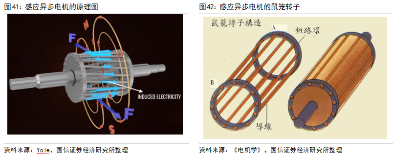
The stator of induction AC motors is fundamentally the same as that of permanent magnet synchronous motors, with the main difference being in the rotor, which typically uses a copper or aluminum squirrel cage structure. According to Faraday’s law of electromagnetic induction, placing a closed conductor in a magnetic field will induce electromotive force in the loop due to the changing magnetic field, generating induced current. According to Lorentz force law, electromagnetic force will act on the current-carrying coil, causing the coil to rotate, and the rotor begins to rotate. Each bar in the squirrel cage will generate induced current, which shorts at both ends of the squirrel cage, causing the rotor to start rotating. The rotor is equipped with thin insulated iron core sheets, ensuring minimal eddy current losses. The rotor rotates at a speed slightly lower than the synchronous speed, and this difference is known as slip, which is generally about 2%-6% of the synchronous speed. Asynchronous motors do not require permanent magnets, commutators, or position sensors, can self-start, and the rotor speed is positively correlated with the speed of the magnetic field, which is in turn positively correlated with the frequency of the input AC power supply.
The main advantages and disadvantages of permanent magnet synchronous motors revolve around the rotor permanent magnet materials, while the advantages and disadvantages of induction asynchronous motors revolve around the rotor squirrel cage structure. Since the rotor does not use permanent magnets but rather a field excitation squirrel cage structure, the primary advantages of induction asynchronous motors include low cost, low difficulty in weak magnetic control, high reliability, high temperature resistance, vibration resistance, and strong overload capacity. The main disadvantages include lower power density, larger size and weight, lower energy conversion efficiency, and the need for a separate cooling system for the rotor.
In summary, the above three issues of permanent magnet synchronous motors—weak magnetic control issues, back electromotive force issues, and demagnetization issues in high-temperature vibration environments—are limitations in high-speed conditions. These factors explain why electric vehicles equipped with permanent magnet synchronous motors often excel in zero-to-hundred acceleration performance but show weak secondary acceleration under high-speed cruising conditions and have limited peak speeds, making it difficult to sustain high-speed cruising.
Comparing the efficiency graphs of permanent magnet synchronous motors and induction motors, we can clearly see that the peak efficiency of permanent magnet synchronous motors is higher than that of induction asynchronous motors, but the high-efficiency range is more concentrated in relatively low-speed areas, while the high-efficiency range of induction asynchronous motors extends more into the high-speed region.
4) Self-Starting Issues: Once the power supply is connected, the rotating magnetic field is immediately generated and rotates at high speed. The rotor, due to inertia, cannot follow immediately. As the stator magnetic poles repeatedly pass the rotor magnetic poles, the magnetic forces acting on the rotor magnetic poles are equal in magnitude but opposite in direction, resulting in zero average torque due to the very short time interval. Therefore, permanent magnet synchronous motors cannot self-start. Solving the self-starting issue requires additional configuration of an inverter (external frequency conversion, slow speed increase) or incorporating a squirrel cage structure from an induction motor into the rotor.
5) Cost Issues: The rotor of permanent magnet synchronous motors requires rare earth materials like neodymium-iron-boron, leading to material costs that are significantly higher than those of induction asynchronous motors. For example, for a common 30KW power drive motor, the material costs of neodymium-iron-boron, copper, and steel are about 68% higher than those of induction asynchronous motors. The cost of neodymium-iron-boron materials accounts for up to 71% of the three main material costs in permanent magnet synchronous motors.
According to data from the United States Geological Survey, in 2020, global rare earth reserves were approximately 116 million tons, with China’s rare earth reserves accounting for about 44.0 million tons, or 37.9% of global rare earth reserves. The abundant rare earth resources in China have laid a foundation for the widespread use of permanent magnet synchronous motors.
The stator of induction AC motors is fundamentally the same as that of permanent magnet synchronous motors, with the main difference being in the rotor, which typically uses a copper or aluminum squirrel cage structure. According to Faraday’s law of electromagnetic induction, placing a closed conductor in a magnetic field will induce electromotive force in the loop due to the changing magnetic field, generating induced current. According to Lorentz force law, electromagnetic force will act on the current-carrying coil, causing the coil to rotate, and the rotor begins to rotate. Each bar in the squirrel cage will generate induced current, which shorts at both ends of the squirrel cage, causing the rotor to start rotating. The rotor is equipped with thin insulated iron core sheets, ensuring minimal eddy current losses. The rotor rotates at a speed slightly lower than the synchronous speed, and this difference is known as slip, which is generally about 2%-6% of the synchronous speed. Asynchronous motors do not require permanent magnets, commutators, or position sensors, can self-start, and the rotor speed is positively correlated with the speed of the magnetic field, which is in turn positively correlated with the frequency of the input AC power supply.
The main advantages and disadvantages of permanent magnet synchronous motors revolve around the rotor permanent magnet materials, while the advantages and disadvantages of induction asynchronous motors revolve around the rotor squirrel cage structure. Since the rotor does not use permanent magnets but rather a field excitation squirrel cage structure, the primary advantages of induction asynchronous motors include low cost, low difficulty in weak magnetic control, high reliability, high temperature resistance, vibration resistance, and strong overload capacity. The main disadvantages include lower power density, larger size and weight, lower energy conversion efficiency, and the need for a separate cooling system for the rotor.
 It is worth mentioning that induction motors almost do not have armature reaction, and their performance in high-speed conditions often surpasses that of permanent magnet synchronous motors. However, at low speeds, as the magnetic current in the rotor is inversely proportional to the rotor speed, the magnetic current establishes a magnetic field without doing work, leading to the phenomenon where the lower the speed of the asynchronous induction motor, the greater the reactive power and the lower the motor efficiency.
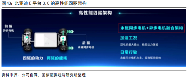
Permanent magnet synchronous motors have high starting torque but weak performance in high-speed conditions, while induction asynchronous motors have low starting torque but strong performance in high-speed conditions. The two complement each other, and leading electric vehicle companies like Tesla and BYD often choose front-drive induction asynchronous motors paired with rear-drive permanent magnet synchronous motors.
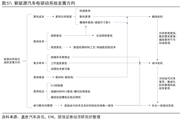
Development Trends: Flat Wire, Oil Cooling, Multi-in-One
As mentioned earlier, the special performance requirements of new energy vehicle drive motors mainly manifest in high power density, wide speed range, high starting torque, broad efficiency range, and strong cooling needs. Therefore, the development trends of new energy vehicle drive motors also revolve around these performances, with the current mainstream directions being flat wire motors, oil-cooled motors, and multi-in-one electric drive assemblies.
Flat wire motors have higher power density, with larger gaps between flat copper wires, allowing cooling oil to penetrate easily. The development of flat wire motors promotes the application of direct oil cooling technology. Additionally, the cooling oil has good insulation properties and can be used as lubricating oil for reducers and gear bearings, as well as to collect waste heat from the motor for battery pack insulation. Direct oil cooling technology accelerates the integration process of the entire vehicle’s thermal management system, promoting the development of multi-in-one electric drive system assemblies.
Flat Wire Motor: Improving Efficiency and Reducing Losses, with Increases in Copper Wire, Insulation Coating, and Equipment
Flat wire motors refer to replacing the traditional cylindrical enameled copper wire in the stator winding with flat wire processed into a hairpin shape. In the cross-section of the round wire motor’s stator, there are large gaps left between the round copper wires, while the rectangular copper wires in the flat wire motor’s stator cross-section can fill the space better, improving the slot fill factor. This is the fundamental difference between flat wire motors and round wire motors.
Flat wire motors can improve the bare copper slot fill rate by 20%-30% compared to traditional round wire motors. An increase in slot fill rate means that the motor can output higher power and torque under the same volume conditions; or, under the same power conditions, the outer diameter and volume of the motor can be reduced, thereby reducing the weight of the motor. Therefore, flat wire winding motors have a higher power density, allowing permanent magnet motors to continue to develop towards miniaturization.
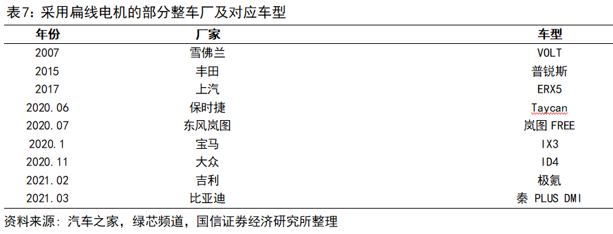
Currently, more and more vehicle models are adopting flat wire winding motors, including Toyota Prius, Volkswagen ID4, BYD Qin PLUS DMI, Geely Zeekr, and domestic Tesla Model 3/Model Y.
Compared to round wire motors, the primary advantages of flat wire motors are reduced losses and improved efficiency. In permanent magnet synchronous motors, copper losses (mainly losses in the stator winding) account for about 65%, iron losses (losses in the stator and rotor iron cores) account for about 20%, and other losses account for a relatively low proportion. The iron loss levels of flat wire motors and round wire motors are similar, with the main difference being in copper loss.
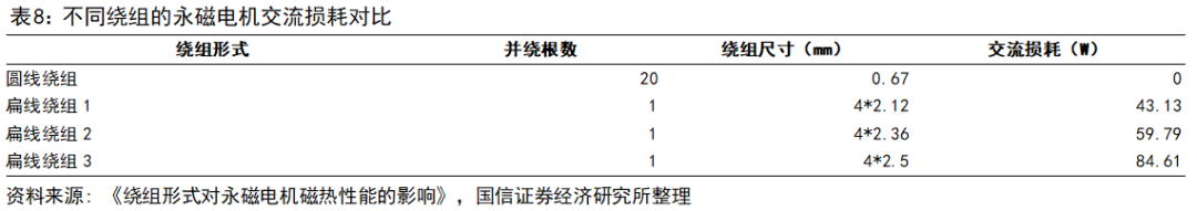
Copper losses can be specifically divided into DC losses and AC losses. Both round wire and flat wire have DC losses, but the round wire winding usually has negligible AC losses due to the smaller cross-section size of individual windings, while flat wire windings, due to their larger conductor cross-section size, are significantly affected by skin effect and proximity effect, making AC losses important as well.
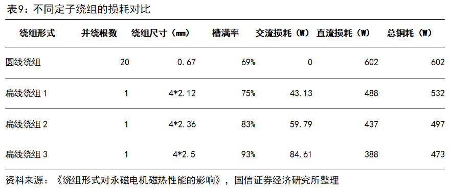
In terms of DC losses, with the number of phases and effective current given, DC losses are proportional to the DC resistance of the windings. Since round wires are thinner, their resistance is higher, thus the DC losses of round wire motors are generally higher than those of flat wire motors under the same conditions. According to the simulation calculations in “The Influence of Winding Form on the Magnetic Thermal Performance of Permanent Magnet Motors,” the DC losses of a permanent magnet synchronous motor with a rated power of 35KW were simulated using finite element software, resulting in a DC loss of 601.6W for round wire windings, while flat wire windings had a DC loss of 388-488W, a reduction of 113-214W compared to round wire windings, with a decrease of 19%-36%.
It is worth mentioning that induction motors almost do not have armature reaction, and their performance in high-speed conditions often surpasses that of permanent magnet synchronous motors. However, at low speeds, as the magnetic current in the rotor is inversely proportional to the rotor speed, the magnetic current establishes a magnetic field without doing work, leading to the phenomenon where the lower the speed of the asynchronous induction motor, the greater the reactive power and the lower the motor efficiency.
Permanent magnet synchronous motors have high starting torque but weak performance in high-speed conditions, while induction asynchronous motors have low starting torque but strong performance in high-speed conditions. The two complement each other, and leading electric vehicle companies like Tesla and BYD often choose front-drive induction asynchronous motors paired with rear-drive permanent magnet synchronous motors.
Development Trends: Flat Wire, Oil Cooling, Multi-in-One
As mentioned earlier, the special performance requirements of new energy vehicle drive motors mainly manifest in high power density, wide speed range, high starting torque, broad efficiency range, and strong cooling needs. Therefore, the development trends of new energy vehicle drive motors also revolve around these performances, with the current mainstream directions being flat wire motors, oil-cooled motors, and multi-in-one electric drive assemblies.
Flat wire motors have higher power density, with larger gaps between flat copper wires, allowing cooling oil to penetrate easily. The development of flat wire motors promotes the application of direct oil cooling technology. Additionally, the cooling oil has good insulation properties and can be used as lubricating oil for reducers and gear bearings, as well as to collect waste heat from the motor for battery pack insulation. Direct oil cooling technology accelerates the integration process of the entire vehicle’s thermal management system, promoting the development of multi-in-one electric drive system assemblies.
Flat Wire Motor: Improving Efficiency and Reducing Losses, with Increases in Copper Wire, Insulation Coating, and Equipment
Flat wire motors refer to replacing the traditional cylindrical enameled copper wire in the stator winding with flat wire processed into a hairpin shape. In the cross-section of the round wire motor’s stator, there are large gaps left between the round copper wires, while the rectangular copper wires in the flat wire motor’s stator cross-section can fill the space better, improving the slot fill factor. This is the fundamental difference between flat wire motors and round wire motors.
Flat wire motors can improve the bare copper slot fill rate by 20%-30% compared to traditional round wire motors. An increase in slot fill rate means that the motor can output higher power and torque under the same volume conditions; or, under the same power conditions, the outer diameter and volume of the motor can be reduced, thereby reducing the weight of the motor. Therefore, flat wire winding motors have a higher power density, allowing permanent magnet motors to continue to develop towards miniaturization.
Currently, more and more vehicle models are adopting flat wire winding motors, including Toyota Prius, Volkswagen ID4, BYD Qin PLUS DMI, Geely Zeekr, and domestic Tesla Model 3/Model Y.
Compared to round wire motors, the primary advantages of flat wire motors are reduced losses and improved efficiency. In permanent magnet synchronous motors, copper losses (mainly losses in the stator winding) account for about 65%, iron losses (losses in the stator and rotor iron cores) account for about 20%, and other losses account for a relatively low proportion. The iron loss levels of flat wire motors and round wire motors are similar, with the main difference being in copper loss.
Copper losses can be specifically divided into DC losses and AC losses. Both round wire and flat wire have DC losses, but the round wire winding usually has negligible AC losses due to the smaller cross-section size of individual windings, while flat wire windings, due to their larger conductor cross-section size, are significantly affected by skin effect and proximity effect, making AC losses important as well.
In terms of DC losses, with the number of phases and effective current given, DC losses are proportional to the DC resistance of the windings. Since round wires are thinner, their resistance is higher, thus the DC losses of round wire motors are generally higher than those of flat wire motors under the same conditions. According to the simulation calculations in “The Influence of Winding Form on the Magnetic Thermal Performance of Permanent Magnet Motors,” the DC losses of a permanent magnet synchronous motor with a rated power of 35KW were simulated using finite element software, resulting in a DC loss of 601.6W for round wire windings, while flat wire windings had a DC loss of 388-488W, a reduction of 113-214W compared to round wire windings, with a decrease of 19%-36%.
 In terms of AC losses, we have already mentioned the back electromotive force issue when discussing permanent magnet synchronous motors. In high-speed rotating motors, the stator coil generates back electromotive force due to cutting magnetic field lines. The magnetic flux generating stator eddy currents mainly consists of three parts: the motor’s fundamental frequency magnetic flux (fundamental wave), stator slotting, core saturation, and internal harmonics produced by rotor motion, as well as external harmonics generated by PWM inverters. Additionally, AC losses increase due to skin effect and proximity effect caused by alternating current.
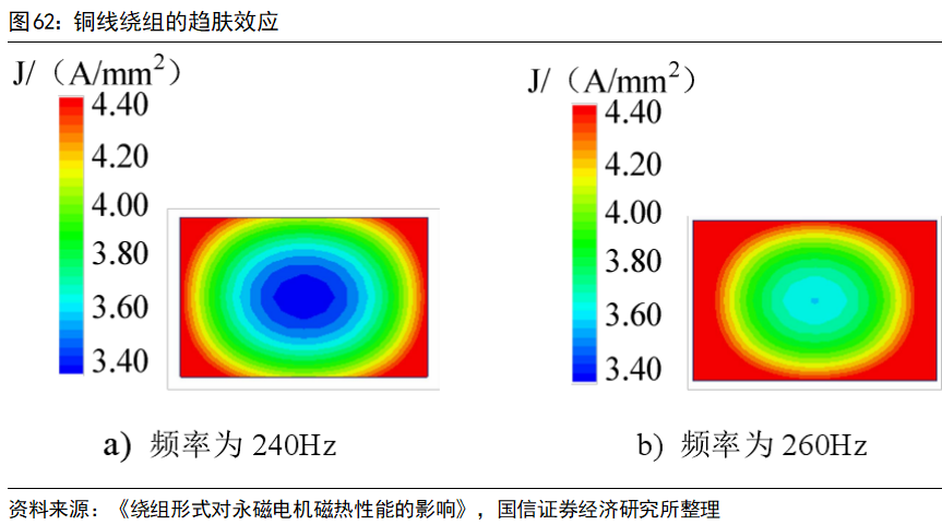
Skin effect refers to the phenomenon where when alternating current flows through a conductor, the changing magnetic field around the conductor induces an induced current within the conductor, resulting in a stronger back electromotive force internally than at the surface, leading to uneven current distribution across the conductor’s cross-section, concentrating towards the outer surface. The higher the current frequency, the stronger the back electromotive force and the more pronounced the skin effect.
In terms of AC losses, we have already mentioned the back electromotive force issue when discussing permanent magnet synchronous motors. In high-speed rotating motors, the stator coil generates back electromotive force due to cutting magnetic field lines. The magnetic flux generating stator eddy currents mainly consists of three parts: the motor’s fundamental frequency magnetic flux (fundamental wave), stator slotting, core saturation, and internal harmonics produced by rotor motion, as well as external harmonics generated by PWM inverters. Additionally, AC losses increase due to skin effect and proximity effect caused by alternating current.
Skin effect refers to the phenomenon where when alternating current flows through a conductor, the changing magnetic field around the conductor induces an induced current within the conductor, resulting in a stronger back electromotive force internally than at the surface, leading to uneven current distribution across the conductor’s cross-section, concentrating towards the outer surface. The higher the current frequency, the stronger the back electromotive force and the more pronounced the skin effect.
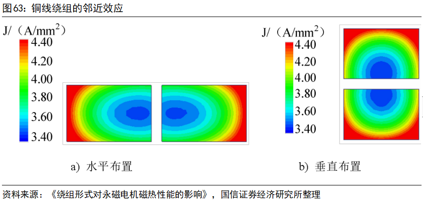
 Proximity effect refers to the phenomenon where when alternating current flows through closely spaced conductors, each conductor is subjected to the electromagnetic field generated by its own current as well as that generated by the current in nearby conductors, causing the current distribution in each conductor to be unevenly influenced by adjacent conductors. If the current directions of two conductors are the same, the current concentrates towards both sides; if the current directions are opposite, the current concentrates towards the center.
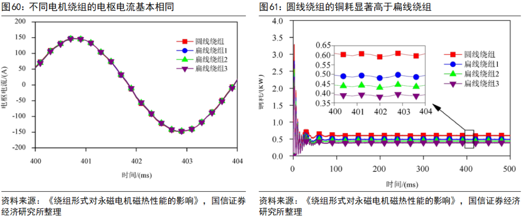
According to “The Influence of Winding Form on the Magnetic Thermal Performance of Permanent Magnet Motors,” when measuring the AC losses of a permanent magnet synchronous motor with a rated power of 35KW using finite element software, it can be clearly seen that the larger the flat wire winding size, the greater the AC losses.
Overall, in terms of total copper losses, flat wire motors still hold an advantage, and the higher the slot fill rate, the greater the advantage. The flat wire winding with the highest slot fill rate compared to the round wire winding has a total copper loss reduction of 21%.
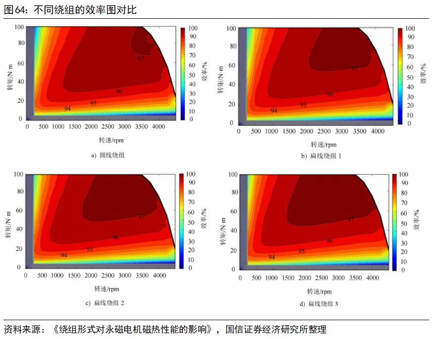
Lower losses mean higher efficiency. According to the simulation calculations in “The Influence of Winding Form on the Magnetic Thermal Performance of Permanent Magnet Motors,” the maximum efficiency of the motor can reach 97%. The maximum efficiency operating area of round wire windings is relatively small, while that of flat wire windings is comparatively large and positively correlated with the slot fill rate. The efficiency of flat wire motors can improve by about 1% compared to round wire motors.
Proximity effect refers to the phenomenon where when alternating current flows through closely spaced conductors, each conductor is subjected to the electromagnetic field generated by its own current as well as that generated by the current in nearby conductors, causing the current distribution in each conductor to be unevenly influenced by adjacent conductors. If the current directions of two conductors are the same, the current concentrates towards both sides; if the current directions are opposite, the current concentrates towards the center.
According to “The Influence of Winding Form on the Magnetic Thermal Performance of Permanent Magnet Motors,” when measuring the AC losses of a permanent magnet synchronous motor with a rated power of 35KW using finite element software, it can be clearly seen that the larger the flat wire winding size, the greater the AC losses.
Overall, in terms of total copper losses, flat wire motors still hold an advantage, and the higher the slot fill rate, the greater the advantage. The flat wire winding with the highest slot fill rate compared to the round wire winding has a total copper loss reduction of 21%.
Lower losses mean higher efficiency. According to the simulation calculations in “The Influence of Winding Form on the Magnetic Thermal Performance of Permanent Magnet Motors,” the maximum efficiency of the motor can reach 97%. The maximum efficiency operating area of round wire windings is relatively small, while that of flat wire windings is comparatively large and positively correlated with the slot fill rate. The efficiency of flat wire motors can improve by about 1% compared to round wire motors.
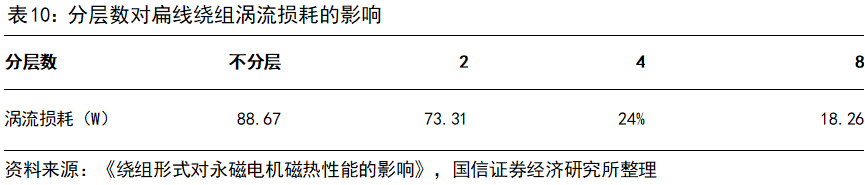
 However, as the motor speed increases, the effects of the skin effect and proximity effect become more pronounced, and the advantages of flat wire motors in terms of high efficiency and low losses may be weakened. When the frequency of the alternating current applied to the flat wire winding is fixed, the larger the cross-sectional area of the flat wire winding, the greater the eddy current losses. In contrast, traditional round wire winding motors typically employ designs that split the windings into multiple finer round wires, mitigating the skin effect on the windings. Therefore, with the equivalent cross-sectional area of the flat wire winding remaining unchanged, dividing the flat wire winding into multiple layers to form multi-layer parallel branches will reduce the cross-sectional area of individual flat wire windings, thereby decreasing eddy current losses caused by the skin effect. According to “The Influence of Winding Form on the Magnetic Thermal Performance of Permanent Magnet Motors,” when the flat wire winding is divided into 2, 4, or 8 layers, the eddy current losses of the corresponding motor model can be significantly reduced, weakening the skin effect.
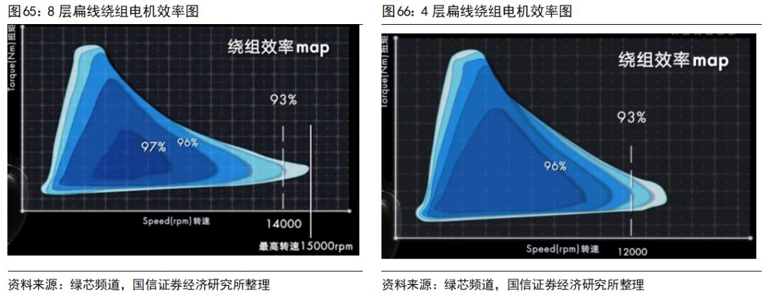
 According to data from Green Core Channel, a 4-layer flat wire winding motor can support a maximum speed of 12,000 RPM within a 93% high-efficiency range, while an 8-layer flat wire winding motor can support a maximum speed of 14,000 RPM within the same range. Moreover, the high-efficiency operating range of the 8-layer flat wire winding motor is significantly larger than that of the 4-layer flat wire winding motor.
Increasing the number of layers of flat wire windings can effectively weaken the skin effect, but the number of layers cannot be increased indefinitely: 1) Manufacturing processes are limited, increasing manufacturing costs; 2) Each layer of winding requires insulation varnish, and excessive layers will reduce the available space in the slots, decreasing the slot fill rate; 3) While increasing layers weakens the skin effect, it strengthens the proximity effect, and excessive layering will lead to increased AC losses.
In addition to improving efficiency and reducing losses, flat wire motors have higher power density (higher slot fill rate), stronger cooling capabilities (lower thermal resistance within the slots), and better NVH performance (lower mechanical and electromagnetic noise) compared to round wire motors.
Compared to round wire motors, the incremental segments of the flat wire motor industry chain mainly focus on copper wire, insulation coating, and production equipment. In terms of copper wire, the processing difficulty of flat copper wire is significantly higher than that of traditional round wire, and the difficulty of coating the insulation also increases, especially at the R corners of flat copper wire. The design process must address how to minimize the R corners, control the coating thickness, ensure uniformity, and guarantee structural strength at the bending points, all of which require high design and processing capabilities. The consistency requirements for flat wire precision are also much higher than for round wire; due to the larger cross-sectional area and fewer layers of a single flat copper wire, inconsistencies in wire dimensions can have a significant negative impact on the overall performance of the winding.
Oil-Cooled Motors: Direct Cooling, Efficient Heat Dissipation
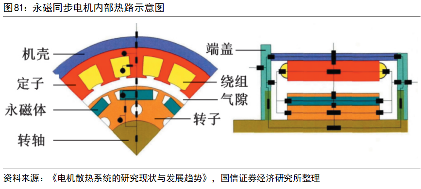
New energy vehicle development has raised higher requirements for motor efficiency, power density, response speed, and vibration noise, prompting motors to evolve towards high precision, high power density, miniaturization, lightweight, and electromechanical integration, resulting in a sharp increase in internal heat generation and a serious lack of effective heat dissipation space, which limits further improvements in the power density of motor systems. High temperatures inside the motor can lead to demagnetization of permanent magnet materials, aging of insulation layers, and increased resistance of copper wire windings at high temperatures, reducing motor efficiency and exacerbating heat generation. According to “Design and Performance Analysis of Cooling Systems for New Energy Vehicle Motors Based on Heat Pipes,” 30%-40% of permanent magnet motor failures are caused by excessive temperature rise.
There are low thermal conductivity materials such as insulation varnish, insulation paper, and air between the contact surfaces of key components such as motor windings, stators, and casings, increasing the contact thermal resistance between the motor components and significantly reducing the heat dissipation efficiency of critical components. The long heat transfer path and large contact thermal resistance between the key heat-generating components inside the motor and the casing pose high requirements for the cooling system.
According to data from Green Core Channel, a 4-layer flat wire winding motor can support a maximum speed of 12,000 RPM within a 93% high-efficiency range, while an 8-layer flat wire winding motor can support a maximum speed of 14,000 RPM within the same range. Moreover, the high-efficiency operating range of the 8-layer flat wire winding motor is significantly larger than that of the 4-layer flat wire winding motor.
Increasing the number of layers of flat wire windings can effectively weaken the skin effect, but the number of layers cannot be increased indefinitely: 1) Manufacturing processes are limited, increasing manufacturing costs; 2) Each layer of winding requires insulation varnish, and excessive layers will reduce the available space in the slots, decreasing the slot fill rate; 3) While increasing layers weakens the skin effect, it strengthens the proximity effect, and excessive layering will lead to increased AC losses.
In addition to improving efficiency and reducing losses, flat wire motors have higher power density (higher slot fill rate), stronger cooling capabilities (lower thermal resistance within the slots), and better NVH performance (lower mechanical and electromagnetic noise) compared to round wire motors.
Compared to round wire motors, the incremental segments of the flat wire motor industry chain mainly focus on copper wire, insulation coating, and production equipment. In terms of copper wire, the processing difficulty of flat copper wire is significantly higher than that of traditional round wire, and the difficulty of coating the insulation also increases, especially at the R corners of flat copper wire. The design process must address how to minimize the R corners, control the coating thickness, ensure uniformity, and guarantee structural strength at the bending points, all of which require high design and processing capabilities. The consistency requirements for flat wire precision are also much higher than for round wire; due to the larger cross-sectional area and fewer layers of a single flat copper wire, inconsistencies in wire dimensions can have a significant negative impact on the overall performance of the winding.
Oil-Cooled Motors: Direct Cooling, Efficient Heat Dissipation
New energy vehicle development has raised higher requirements for motor efficiency, power density, response speed, and vibration noise, prompting motors to evolve towards high precision, high power density, miniaturization, lightweight, and electromechanical integration, resulting in a sharp increase in internal heat generation and a serious lack of effective heat dissipation space, which limits further improvements in the power density of motor systems. High temperatures inside the motor can lead to demagnetization of permanent magnet materials, aging of insulation layers, and increased resistance of copper wire windings at high temperatures, reducing motor efficiency and exacerbating heat generation. According to “Design and Performance Analysis of Cooling Systems for New Energy Vehicle Motors Based on Heat Pipes,” 30%-40% of permanent magnet motor failures are caused by excessive temperature rise.
There are low thermal conductivity materials such as insulation varnish, insulation paper, and air between the contact surfaces of key components such as motor windings, stators, and casings, increasing the contact thermal resistance between the motor components and significantly reducing the heat dissipation efficiency of critical components. The long heat transfer path and large contact thermal resistance between the key heat-generating components inside the motor and the casing pose high requirements for the cooling system.
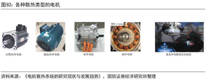
 Air cooling, liquid cooling, and evaporative cooling systems are three common motor cooling systems. Air cooling systems have been widely used in small power motor cooling due to their low cost, high reliability, and ease of installation. Liquid cooling systems have high cooling power, with cooling efficiency reaching 50 times that of air cooling, suitable for scenarios with high heat generation and heat flow density. However, liquid cooling systems require additional circulation liquid paths and sealing systems, increasing the cost and complexity of the motor system. Evaporative cooling systems are mainly applied in megawatt-class large capacity generator sets, utilizing gas-liquid phase change cycles for efficient motor cooling.
 The liquid cooling forms for automotive permanent magnet synchronous motors can be roughly divided into two types: direct cooling and indirect cooling. Indirect cooling is designed with cooling channels inside the casing, where the coolant flows through the entire casing to carry away heat. Direct cooling involves injecting cooling oil into the sealed motor, utilizing the high specific heat capacity of the cooling oil for cooling. Moreover, direct cooling can increase the contact area with the heat source, resulting in better cooling effects. Permanent magnet synchronous motors have significant heat generation at the winding ends; under water cooling, the coolant cannot directly contact the windings, but under oil cooling, the cooling oil can directly contact the windings, leading to higher cooling efficiency and more prominent advantages.
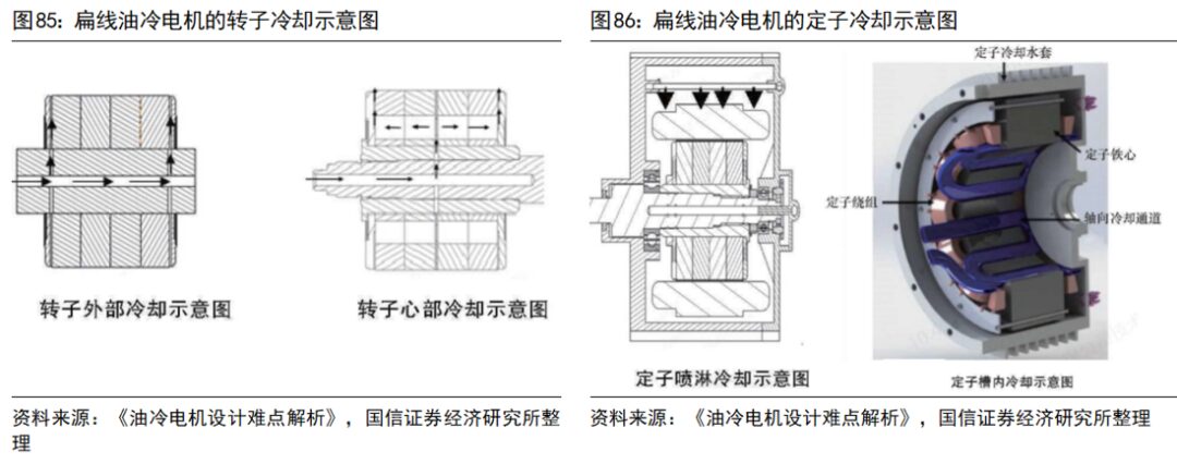
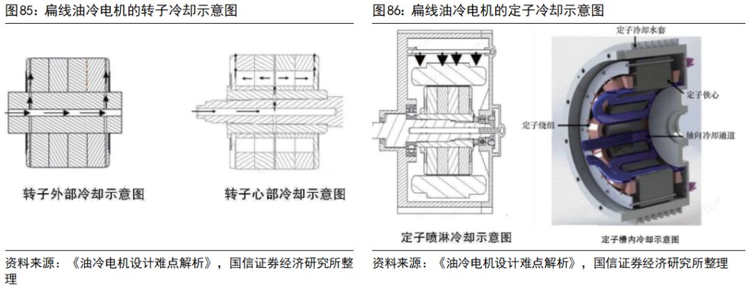
 Oil cooling solutions can generally be divided into three types: 1) Stator Oil Drenching: Oil is sprayed directly onto the stator winding or stator iron core for cooling. 2) Stator Oil Drenching + Rotor Oil Flinging: While the stator is cooled by oil drenching, the rotor also has designed oil channels, and the cooling oil in the rotor oil channel is flung towards the stator under the rotor’s centrifugal force, cooling both the stator and rotor. 3) Internal Oil Path + Stator Oil Drenching + Rotor Oil Flinging: This solution adds internal cooling to the stator based on solution 2, further enhancing the cooling effect.
In terms of rotor cooling, cooling oil is generally introduced into the oil channels between the rotor core and the two end plates through a hollow shaft, flowing out from the end plates under the rotor’s centrifugal force, effectively lowering the working temperature of the magnetic steel, significantly enhancing both the lifespan of the magnetic steel and the output capacity of the motor. In terms of stator cooling, cooling oil is generally sprayed onto the stator windings and iron core through oil drenching, flowing to other locations under the influence of gravity, achieving cooling for the stator.
Oil cooling solutions can generally be divided into three types: 1) Stator Oil Drenching: Oil is sprayed directly onto the stator winding or stator iron core for cooling. 2) Stator Oil Drenching + Rotor Oil Flinging: While the stator is cooled by oil drenching, the rotor also has designed oil channels, and the cooling oil in the rotor oil channel is flung towards the stator under the rotor’s centrifugal force, cooling both the stator and rotor. 3) Internal Oil Path + Stator Oil Drenching + Rotor Oil Flinging: This solution adds internal cooling to the stator based on solution 2, further enhancing the cooling effect.
In terms of rotor cooling, cooling oil is generally introduced into the oil channels between the rotor core and the two end plates through a hollow shaft, flowing out from the end plates under the rotor’s centrifugal force, effectively lowering the working temperature of the magnetic steel, significantly enhancing both the lifespan of the magnetic steel and the output capacity of the motor. In terms of stator cooling, cooling oil is generally sprayed onto the stator windings and iron core through oil drenching, flowing to other locations under the influence of gravity, achieving cooling for the stator.
 Water cooling systems have potential issues such as rust, blockage, and leakage. Once a leak occurs, it directly jeopardizes the safety of the motor, necessitating high reliability sealing for the water cooling system’s circulation pipelines. Compared to water media, oil media have advantages such as good insulation, high dielectric constant, low freezing point, and high boiling point, enhancing the motor system’s adaptability to external environments and avoiding issues like cavitation and scaling. The cooling oil in direct oil cooling systems directly contacts the motor’s heat-generating components, providing cooling efficiency far superior to water cooling systems. The drive motor in BYD’s DMI system employs direct injection rotor oil cooling technology, which can increase the motor’s power density by 32%.
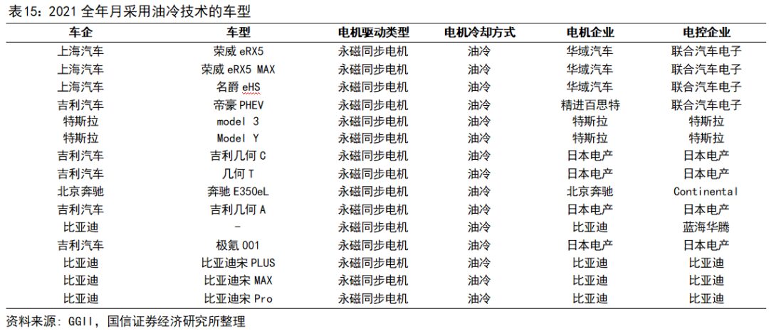
 According to data from Gaogong Lithium Battery, in 2021, major vehicle manufacturers in China using oil cooling technology included BYD, Tesla, Geely, SAIC, and Mercedes-Benz, with models including BYD Song MAX, BYD Song Pro, BYD Song Plus, Tesla Model 3, Tesla Model Y, SAIC Roewe eRX5, Geely Geometry C, Geely Emgrand PHEV, and Zeekr 001. Corresponding motor suppliers mainly include BYD self-produced, Tesla self-produced, Nidec, Jieneng Baishite, and Huayu Automotive.
 Additionally, due to the larger gaps between the flat wire end conductors, when the nozzle releases oil, it directly penetrates into the flat wire winding ends, carrying away heat from each conductor. In contrast, the round wire winding ends, after varnishing, become a solid whole, making it difficult for cooling oil to penetrate internally and carry away heat from the intermediate layer conductors, easily forming thermal islands within the windings. Therefore, flat wire and oil cooling are a golden pair; when used together, they can significantly enhance cooling capabilities, thereby improving power density.
Compared to traditional water-cooled motors, the main incremental segments in oil-cooled motors involve electronic oil pumps, filters, and radiators, with market prices typically around 150/50/50 yuan, fluctuating based on the purchasing volume of manufacturers. Additionally, the cooling oil used in oil-cooled motors is generally ATF oil (automatic transmission fluid).
Multi-in-One Electric Drive System Assembly: Integration Achieving Cost Reduction and Efficiency Improvement
New energy vehicles have increasing requirements for range, power density, and energy utilization efficiency, leading to rapid development of electric drive systems towards integration, miniaturization, and lightweight. Currently, multi-in-one electric drive systems have been released in configurations such as three-in-one, four-in-one, six-in-one, seven-in-one, and even eight-in-one, with the most common still being the three-in-one electric drive system.
The “multi-in-one” integration scheme of electric drive systems allows for the sharing of housings, coupling, and cooling systems among the system’s components (for example, the lubricating oil for the reducer can be used to cool the drive motor, while Tesla recycles motor heat to keep the battery warm), sharing circuits and power semiconductors, reducing cable usage, effectively shrinking the size and weight of the electric drive system, enhancing power density, and achieving lightweight.
1) Broad Applicability: Multi-in-one electric drive systems require top-level design and planning based on vehicle platforms, which can significantly shorten development cycles and meet the needs of various vehicle models at lower costs;
2) Cost Reduction: Reducing high-voltage wiring harnesses, connectors, and other components within the powertrain reduces weight and lowers costs;
3) Space Optimization: More compactly integrating motors, inverters, reducers, and other modules frees up space, facilitating vehicle layout;
4) Improved Energy Efficiency: Reducing or shortening the connection wiring between the inverter and motor decreases power losses, enhancing the energy utilization efficiency of the electric drive system;
Common three-in-one electric drive systems can be roughly divided into five types based on the position of the motor controller. The motor controller may be distributed in parallel with the drive motor and reducer, integrated within the drive motor, or integrated within the reducer, each having advantages and disadvantages in terms of size, wiring usage, and technical difficulty.
The main barriers to multi-in-one electric drive systems include:
1) Product Design Coordination: The core components in the electric drive system, such as the motor, reducer, and inverter, may come from different suppliers, requiring integrated manufacturers to unify design, planning, and production, facilitating cross-domain coordination.
2) Cooling System Integration: Multi-in-one electric drive systems often share housings and cooling systems, significantly raising the design requirements for the cooling system due to the heat sources from the motor, motor controller, DC/DC converter, etc.
3) Quality Control Issues: The integration of multiple core components places high demands on production processes and quality control levels, and the impact of a single component failure on the integrated system cannot be overlooked.
4) EMC Issues: The integration of numerous electronic components and drive motors necessitates finding a balance concerning electromagnetic interference issues.
Source: Guosen Securities
Additionally, due to the larger gaps between the flat wire end conductors, when the nozzle releases oil, it directly penetrates into the flat wire winding ends, carrying away heat from each conductor. In contrast, the round wire winding ends, after varnishing, become a solid whole, making it difficult for cooling oil to penetrate internally and carry away heat from the intermediate layer conductors, easily forming thermal islands within the windings. Therefore, flat wire and oil cooling are a golden pair; when used together, they can significantly enhance cooling capabilities, thereby improving power density.
Compared to traditional water-cooled motors, the main incremental segments in oil-cooled motors involve electronic oil pumps, filters, and radiators, with market prices typically around 150/50/50 yuan, fluctuating based on the purchasing volume of manufacturers. Additionally, the cooling oil used in oil-cooled motors is generally ATF oil (automatic transmission fluid).
Multi-in-One Electric Drive System Assembly: Integration Achieving Cost Reduction and Efficiency Improvement
New energy vehicles have increasing requirements for range, power density, and energy utilization efficiency, leading to rapid development of electric drive systems towards integration, miniaturization, and lightweight. Currently, multi-in-one electric drive systems have been released in configurations such as three-in-one, four-in-one, six-in-one, seven-in-one, and even eight-in-one, with the most common still being the three-in-one electric drive system.
The “multi-in-one” integration scheme of electric drive systems allows for the sharing of housings, coupling, and cooling systems among the system’s components (for example, the lubricating oil for the reducer can be used to cool the drive motor, while Tesla recycles motor heat to keep the battery warm), sharing circuits and power semiconductors, reducing cable usage, effectively shrinking the size and weight of the electric drive system, enhancing power density, and achieving lightweight.
1) Broad Applicability: Multi-in-one electric drive systems require top-level design and planning based on vehicle platforms, which can significantly shorten development cycles and meet the needs of various vehicle models at lower costs;
2) Cost Reduction: Reducing high-voltage wiring harnesses, connectors, and other components within the powertrain reduces weight and lowers costs;
3) Space Optimization: More compactly integrating motors, inverters, reducers, and other modules frees up space, facilitating vehicle layout;
4) Improved Energy Efficiency: Reducing or shortening the connection wiring between the inverter and motor decreases power losses, enhancing the energy utilization efficiency of the electric drive system;
Common three-in-one electric drive systems can be roughly divided into five types based on the position of the motor controller. The motor controller may be distributed in parallel with the drive motor and reducer, integrated within the drive motor, or integrated within the reducer, each having advantages and disadvantages in terms of size, wiring usage, and technical difficulty.
The main barriers to multi-in-one electric drive systems include:
1) Product Design Coordination: The core components in the electric drive system, such as the motor, reducer, and inverter, may come from different suppliers, requiring integrated manufacturers to unify design, planning, and production, facilitating cross-domain coordination.
2) Cooling System Integration: Multi-in-one electric drive systems often share housings and cooling systems, significantly raising the design requirements for the cooling system due to the heat sources from the motor, motor controller, DC/DC converter, etc.
3) Quality Control Issues: The integration of multiple core components places high demands on production processes and quality control levels, and the impact of a single component failure on the integrated system cannot be overlooked.
4) EMC Issues: The integration of numerous electronic components and drive motors necessitates finding a balance concerning electromagnetic interference issues.
Source: Guosen Securities
Advertising Cooperation ▎ 18240442679(WeChat same number) Mr. Fu
Editor ▎ Yu Yongchu
Review ▎Cao Xuelei
Gold Powder MallPopular Book Rankings
☞ Favorite Book Rankings
☞ Mechanical Book Rankings
☞ Production Management Rankings
☞ Design Software Rankings

-
To publish an article in the 2023 annual issue of “Automotive Engineer,” here’s what you need to do
-
April Car Sales: New Energy Vehicles account for 29.5% market share, with new car manufacturers “Weixiaoli” showing divergent performances
-
Domestic Solid-State Battery and Process Patents
-
A large automotive supply chain behind many domestic car companies, recommended for collection!
-
Discussion on Application Technologies of Automotive Parts Processing Tools
-
BYD will supply batteries to Tesla; the eight major processes of blade battery production are not simple!
-
What are “4680” and “full-tab” batteries? No company dares to publicly disclose this technology at this stage!
-
3D Printing Tools Assist Efficient Processing of Motor Housings and Transmissions
-
It is a “smart-level” process tool that ensures automobile quality and plays an indispensable role in industrial production
-
Necessity and Goals of Building Digital Factories for New Energy Batteries
-
5G empowerment recommended by Ren Zhengfei has been published! This PPT lets you know everything about the content.
-
Great Wall’s Xushui Intelligent Factory: 286 Robots Creating Luxury and Safety for VV5s

For submissions, please click on the image above