Source: Jicheng Training Network (Teacher Liang Zhibin) ▏Siemens S7-200 Series 17
1.6.4 Network Wiring
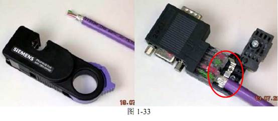
For RS485 networks such as PPI, MPI, and Profibus, it is recommended to use the cables and connectors shown in Figure 1-33. When using, pay attention to:
• Do not reverse the wiring;
• The cable shielding layer must be pressed onto the metal part of the connector, as indicated by the red circle in the figure.
• You can use the Siemens quick wire stripper (Order No. 6GK1905-6AA00).
A standard RS-485 network uses terminal resistors and bias resistors. When the network connection is very short, temporary, or for laboratory testing, terminal and bias resistors can also be omitted.
• Terminal resistor: A resistor connected in parallel across a pair of communication lines at both ends of the linear network. According to transmission line theory, terminal resistors can absorb reflected waves on the network, effectively enhancing signal strength. The value of two parallel terminal resistors should be approximately equal to the characteristic impedance of the transmission line at the communication frequency.
• Bias resistor: The bias resistor is used to ensure the relative relationship of the A and B signals under complex electrical conditions, ensuring the reliability of the “0” and “1” signals.
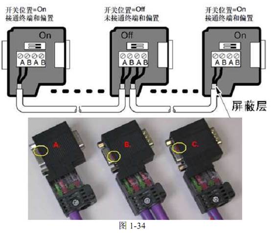
Siemens network connectors have built-in terminal and bias resistors, which can be conveniently turned on or off with a switch. The values of the terminal and bias resistors fully meet the requirements of Siemens communication ports and cables. The resistors need to be set to ON at the beginning and end of the network, as shown in Figure 1-34.
When using RS485 networks, the following precautions should be noted:
• Use genuine cables and connectors;
• Connectors must be made according to specifications;
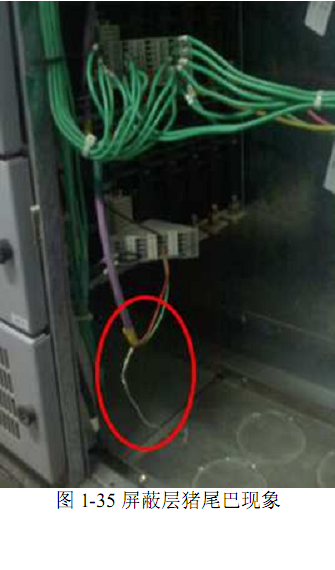
• The shielding layer must be properly grounded, avoiding “pig tails,” as shown in Figure 1-35;
• The PE terminal of the CPU or module must be grounded; otherwise, the shielding layer will be ineffective;
• Communication cables should be kept away from power cables; avoid parallel routing;
• Maintain a common mode voltage difference between communication ports within a certain range. For non-isolated communication ports (such as those on the CPU), ensuring they are at the same potential is very important. When networking S7-200 CPUs, you can connect the M terminals of the sensor power outputs of all CPU modules in series with wires. When communicating between the S7-200 CPU and the inverter, connect the M terminals of all inverter communication ports (in the Siemens MM4 series, this is terminal 2) together and connect them to the M of the sensor power on the CPU.
(This course is one of the premium courses from Jicheng Training Network and is absolutely worth a look!)
This article’s content is from: Jicheng paid video tutorial + Jicheng supplementary internal book content “Siemens S7-200 PLC From Beginner to Expert” Video address: http://www.jcpeixun.com/lesson/3/
Copyright belongs to Jicheng. Unauthorized reproduction will be pursued!
Sharing is a virtue!

Click [Read Original] to see more wonderful content!
▼