If you are a power engineer, you can skip the introduction to power modules. However, if you are a beginner or studying microcontrollers, it is best to read carefully.
A power module is a power supply that can be directly mounted on a printed circuit board (see Figure 1). It is designed to provide power to application-specific integrated circuits (ASICs), digital signal processors (DSPs), microprocessors, memory, field-programmable gate arrays (FPGAs), and other digital or analog loads. Generally, these modules are referred to as point-of-load (POL) power supply systems or point-of-use power supply systems (PUPS). Due to the numerous advantages of modular structures, various modules are widely adopted in high-performance telecommunications, networking, and data communication systems. Although there are many benefits to using modules, engineers often overlook reliability and measurement issues when designing power modules and most on-board DC/DC converters. This article will delve into these issues and propose relevant solutions.
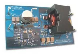
Figure 1, Power Supply
Advantages of Using Power Modules
Currently, various suppliers have launched different power modules in the market, with varying input voltages, output power, functions, and topologies. Using power modules can save development time, allowing products to be brought to market faster, making power modules superior to integrated solutions. Power modules also have several other advantages:
● Each module can be rigorously tested individually to ensure high reliability, including power-on testing to eliminate non-compliant products. In contrast, integrated solutions are more challenging to test because the entire power system is closely linked to other functional systems on the circuit.
● Different suppliers can design modules of the same size according to existing technical standards, providing engineers designing power supplies with various options.
● The design and testing of each module are conducted according to standard performance specifications, helping to reduce the risks associated with adopting new technologies.
● If an integrated solution encounters a problem with the power supply system, the entire main board must be replaced; with a modular design, only the problematic module needs to be replaced, which helps save costs and development time.
Commonly Overlooked Design Issues in Power Modules
Despite the numerous advantages of modular designs, there are inherent issues in modular designs and on-board DC/DC converter designs that many people are unaware of or do not give sufficient attention to. Some of these issues include:
● Measurement of output noise;
● Design of magnetic systems;
● Breakdown phenomena in synchronous buck converters;
● Reliability of printed circuit boards.
These issues will be discussed in detail below, along with various simple techniques to address them.
Measurement Techniques for Output Noise
All switch-mode power supplies will output noise. The higher the switching frequency, the more critical it is to use the correct measurement techniques to ensure that the measured data is accurate and reliable. When measuring output noise and other important data, a Tektronix probe (commonly referred to as a cold spray probe) as shown in Figure 2 can be used to ensure that the measurements are accurate and meet expectations. This measurement technique also minimizes ground loop issues.
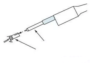
Figure 2, Measuring Output Noise Digitally
When conducting measurements, we must also consider the propagation delay that measuring instruments may introduce. Most current probes have a longer propagation delay than voltage probes. Therefore, simultaneous display of voltage and current waveforms cannot ensure measurement accuracy unless the different delays are manually balanced.
Current probes also introduce inductance into the circuit. A typical current probe introduces 600nH of inductance. For high-frequency circuit designs, since the circuit can only tolerate inductance up to 1mH, the inductance introduced by the probe can affect the accuracy of di/dt current measurements, potentially leading to significant measurement errors. If the inductor is saturated, a more accurate method of measuring current can be employed, such as measuring the voltage across a small shunt resistor in series with the inductor.
Magnetic Design
The reliability of the magnetic core is another frequently overlooked issue. Most output inductors use ferrite cores because ferrite is the lowest-cost material. Approximately 95% of the composition of ferrite cores consists of pure iron particles, which are bonded together using organic adhesives. These adhesives also separate each iron particle, creating air gaps throughout the core.
While ferrite is the raw material for the core, it contains small amounts of impurities such as manganese and chromium, which can affect the reliability of the core, depending on the quantity of impurities present. We can use a scanning electron microscope (SEM) to closely examine the cross-section of the core to determine the relative distribution of impurities. The reliability of the core hinges on whether the material can be predicted and whether its supply is stable and reliable.
If ferrite cores are exposed to high-temperature environments for extended periods, core losses may increase, and once losses increase, they cannot be restored, as the organic adhesives undergo molecular decomposition, leading to increased eddy current losses. This phenomenon is referred to as thermal aging, which may ultimately lead to thermal runaway in the core.
The magnitude of core losses is influenced by several factors, including AC flux density, operating frequency, core size, and material type. For high-frequency operations, most losses are eddy current losses. In contrast, for low-frequency operations, hysteresis losses are the predominant losses.
Eddy current losses can heat the core, thereby affecting efficiency. The cause of eddy current losses is that ferromagnetic materials subjected to varying magnetic flux over time generate circulating currents within the material. By selecting laminated ferromagnetic sheets instead of solid ferromagnetic materials for the core, we can reduce eddy current losses. For example, Metglas, which is made from magnetic tape, is one such core material. Other ferromagnetic product suppliers, such as Magnetics, also produce cores made from magnetic tape.
Suppliers of core products like Micrometals provide engineers designing magnetic products with the latest information and calculations regarding thermal aging of cores. Ferrite cores using inorganic adhesives do not experience thermal aging. Such cores are already available on the market, with Micrometals’ 200C series cores belonging to this category.
Breakdown Phenomena in Synchronous Buck Converters
Point-of-load (POL) power supply systems or point-of-use power supply systems (PUPS) widely use synchronous buck converters (see Figure 3). These synchronous buck converters replace the clamp diode of traditional buck converters with high-side and low-side MOSFETs to reduce losses in load current.
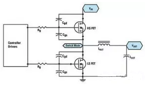
Figure 3, Synchronous Buck Converter
When designing buck converters, engineers often overlook the issue of “breakdown.” Whenever the high-side and low-side MOSFETs are fully or partially turned on simultaneously, a “breakdown” phenomenon occurs, allowing input voltage to directly deliver current to ground.
The breakdown phenomenon can cause current spikes at the moment of switching, preventing the converter from achieving its maximum efficiency. We cannot use current probes to measure breakdown conditions because the probe’s inductance severely interferes with circuit operation. We can check the gate-source voltage of the two field-effect transistors (FETs) to see if spikes occur. This is another method to detect breakdown phenomena (the gate-source voltage of the upper MOSFET can be monitored differentially).
We can reduce the occurrence of breakdown phenomena using the following methods.
Using a controller chip with a “fixed dead time” is one feasible approach. This controller chip ensures that after the upper MOSFET is turned off, there is a delay before the lower MOSFET is turned back on. This method is relatively simple, but care must be taken during implementation. If the dead time is too short, it may not prevent breakdown phenomena. If the dead time is too long, conduction losses will increase because the built-in diode of the lower FET will be conducting throughout the dead time. Since this diode conducts during the dead time, the efficiency of the system using this method depends on the characteristics of the built-in diode of the lower MOSFET.
Another method to reduce breakdown is to use a controller chip with an “adaptive dead time.” The advantage of this method is that it continuously monitors the gate-source voltage of the upper MOSFET to determine when to turn on the lower MOSFET.
When the high-side MOSFET turns on, it induces a dv/dt spike at the gate of the low-side MOSFET through the inductor, raising the gate voltage (see Figure 4). If the gate-source voltage is high enough to turn it on, breakdown phenomena will occur.
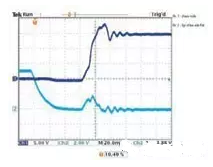
Figure 4, Induced dv/dt Voltage Amplitude at the Low-Side MOSFET
The adaptive dead time controller is responsible for monitoring the gate voltage of the MOSFET externally. Therefore, any newly added external gate resistors will divide the voltage of the controller’s internal pull-down resistor, causing the gate voltage to be higher than what the controller monitors.
Predictive gate driving is another feasible solution, which involves using a digital feedback circuit to detect the conduction state of the built-in diode and adjust the dead time delay to minimize the conduction of the built-in diode, ensuring that the system can achieve maximum efficiency. If this method is used, the controller chip will need to add more pins, which will increase the cost of the chip and the power module.
It is important to note that even with predictive gate driving, there is no guarantee that the field-effect transistors will not turn on due to inductive dv/dt.
Delaying the turn-on of the high-side MOSFET also helps reduce the occurrence of breakdown. While this method can reduce or completely eliminate breakdown phenomena, the downside is that switching losses are higher, and efficiency will decrease. Selecting better MOSFETs can also help reduce the dv/dt voltage amplitude at the gate of the low-side MOSFET. The higher the ratio between Cgs and Cgd, the lower the inductive voltage that appears at the MOSFET gate.
Breakdown testing conditions are often overlooked, such as during load transients—especially whenever the load is released or suddenly reduced—the controller continuously generates narrow frequency pulses. Currently, most high-current systems use multi-phase designs, utilizing driver chips to drive MOSFETs. However, using driver chips complicates the breakdown issue, especially when the load is in a transient state. For example, interference from narrow frequency drive pulses, combined with propagation delays in the driver, can lead to breakdown phenomena.
Most driver chip manufacturers specifically stipulate that the pulse width of the controller must not fall below a certain minimum requirement; if it does, there will be no pulse input to the gate of the MOSFET.
Additionally, manufacturers also add a configurable dead time (TRT) feature to enhance the accuracy of adaptive switching timing. This is done by placing a resistor between the configurable dead time pin and ground to determine the dead time during the high-low transition. This dead time setting feature, combined with propagation delays, can turn off complementary MOSFETs during the transition process to prevent breakdown phenomena in synchronous buck converters.
Reliability
Any module must undergo rigorous testing in the early stages to ensure a reliable design, preventing unexpected issues from arising in the final stages of production. The module must be tested within the customer’s system to ensure that all potential factors that could lead to system failures, such as fan failures, intermittent fan stoppages, etc., are adequately considered. Engineers using distributed structures hope that their designed systems can operate continuously for many years with few or no failures. Given that test data shows that the MTBF of power modules can reach millions of hours, achieving this goal is not particularly difficult.
However, the reliability of printed circuit boards is often overlooked. Currently, the trend is that the area of printed circuit boards is shrinking, while the amount of current they need to handle is increasing, leading to increased current density that may cause hidden or other vias to fail to function properly.
Some hidden vias on printed circuit boards must carry large amounts of current; for these hidden vias, there must be sufficient copper protection around them to ensure a more reliable and durable design. This protective measure can also suppress the thermal expansion in the z-axis; otherwise, if there are any changes in the environmental temperature during production or product use, the hidden vias may become exposed. Engineers must refer to the expertise of printed circuit board manufacturers to thoroughly review the design of printed circuit boards, and PCB manufacturers can provide professional advice on the reliability of PCB designs based on their production capabilities.
Conclusion
To build a reliable power supply system using power modules, we must address design reliability issues. This article focused on several key issues, including the reliability of ferrite cores, characteristics of magnetic systems, breakdown phenomena in synchronous buck converters, and the reliability of printed circuit boards in high-current systems.