J1939 to Modbus Master – ADFweb Gateway Converter– Guangzhou Xinyu IoT
Author: Zou Wuyi Mobile185-020-77899Email[email protected]
1、Product Features: Configurable J1939 to Modbus master gateway supports the following functions:
- Baud rate can be changed via software;
- Electrical isolation between the two buses;
- Can read data requested by the gateway from J1939 frames to Modbus devices;
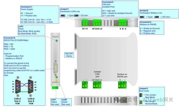
- Power supply range is 8…19 VAC (4 VA) or 8…35 VDC (4 W);
- 35mm DIN rail mounting;
- Operating temperature range is -40°C to 85°C.
Configuration:“J1939 to Modbus gateway” allows J1939 networks to communicate with Modbus networks. You need to install Compositor SW67050 software on your PC to perform the following actions:
- Define parameters for the two communication lines;
- Define J1939 frames;
- Define which Modbus registers to read;
- Update firmware and / or projects.
2、New Project / Open Project: The “New Project” button creates a folder containing the entire device configuration. Device configurations can also be imported and exported: To clone the programmable J1939 configuration to the Modbus gateway (or from Modbus gateway to programmable J1939), the folder and all its contents must be retained; To clone a project for a different version of that project, simply copy the project folder to another name and open the new folder with the “Open Project” button; When creating a new project or opening an existing project, various configuration sections of the software will be accessible:
- Set communication;
- Define J1939 frames;
- Define which Modbus registers to read.
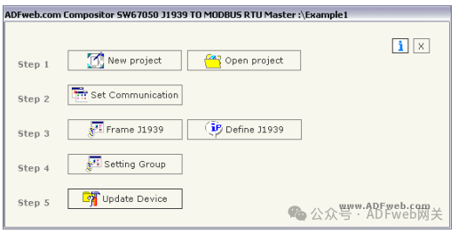
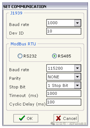
3、Set Communication: This section defines the basic communication parameters for the two buses (J1939 and Modbus). By clicking the “Set Communication” button in the main window (for SW67050, see Figure 3), the “Set Communication” window will appear (see Figure 4):
This window is divided into two parts, one for J1939 and the other for Modbus.
“J1939” Field Meaning:
- In the “Baud Rate” field, you can select the baud rate for the J1939 bus;
- In the “Device ID” field, you can assign an ID to the J1939 end.
“Modbus” Field Meaning:
- If the “RS232” field is checked, the serial line used is RS232; if the “RS485” field is checked, the serial line used is RS485;
- In the “Baud Rate” field, define the baud rate for the serial line;
- In the “Parity” field, define the parity method for the serial line;
- In the “Stop Bits” field, define the number of stop bits;
- In the “Timeout” field, define the maximum time the device waits for a slave response;
- In the “Loop Delay” field, define the delay time between two requests.
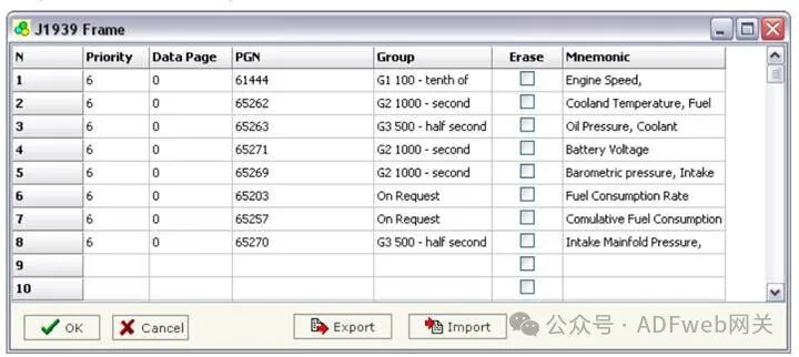
4、FRAME J1939: By clicking the “Frame J1939” button in the main window (for SW67050, see Figure 3), you can open the “J1939 Frame” window (see Figure 5). The meanings of each field are as follows:
- In the “Priority” field, insert the priority of the frame; in the J1939 protocol, the priority is a number between 0 and 7. Where 0 indicates the highest priority, and 7 indicates the lowest priority;
- In the “Data Page” field, insert the data page; in the J1939 protocol, the value of the data page is 0 or 1;
- In the “PGN” field, insert the PGN you wish to read from Modbus to J1939 (in the J1939 protocol, PGN is an identifier);
- In the “Group” field, you can select the sending group of the frame on the J1939 end. Groups are defined in the “Set Group” section. If no group is selected, the default value is “On request”, meaning that other J1939 devices need to request the gateway to send that frame;
- If the “Erase” field is checked, when the main Modbus device does not receive a reply to the request within the “Timeout (ms)” defined in “Set Communication”, the value of the J1939 frame will be set to 0;
- In the “Mnemonic” field, you can insert descriptive information.