This article is approximately 9,800 words long, recommended for saving and reading.
Author | Beiwai Nannxiang
Produced by | Automotive Electronics and Software
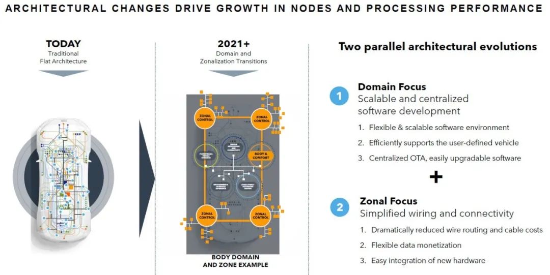
The automotive electronic and electrical architecture is transitioning from a traditional decentralized “flat architecture” to a more efficient “domain control” and “zonal control.” This transformation not only simplifies wiring and hardware integration, reduces costs, but also brings more flexible software development and more efficient OTA upgrade capabilities, laying the foundation for the functional expansion and data applications of smart vehicles.
The zonal aggregator, as the main node for integrating and transmitting data within the vehicle, plays an important role in the vehicle electronic system. The S32K3 series microcontrollers (MCUs) effectively address the challenges faced by zonal aggregators in communication interfaces, power consumption performance, and anti-interference capabilities, providing strong support for the development of intelligent vehicles.
#01
Introduction to Zonal Modules
1.1 Background Introduction
The zonal module (Zonal Modules) is a key component in modern automotive electronic electrical architecture, divided into three levels: Zonal Aggregator, Zonal Controller, and Zonal Processor. Each level gradually enhances in complexity, processing capability, and functionality to meet various system demands.
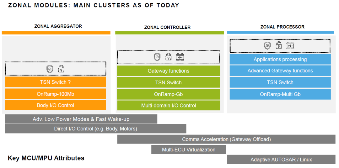
- Zonal Aggregator: Basic I/O control, low bandwidth access, suitable for simple tasks like body control.
- Zonal Controller: Provides gateway and multi-domain control functions, supports Gigabit Ethernet, suitable for complex data interactions.
- Zonal Processor: Advanced application processing and gateway functions, supports multiple Gigabit Ethernet and complex security features, suitable for intelligent driving and advanced infotainment systems.
1.2 Challenges
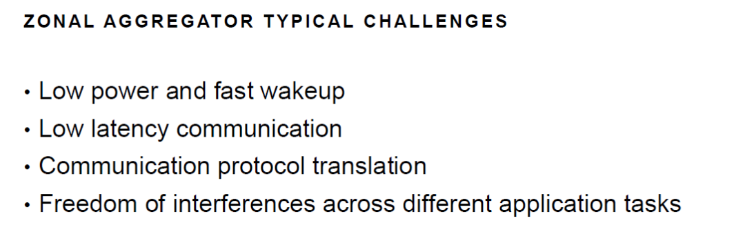
Although the zonal aggregator is at the basic level within the overall architecture, the challenges it faces involve power management, real-time communication, protocol compatibility, and system stability. Addressing these challenges relies not only on the efficient design of hardware (such as low-power MCUs and high-speed communication interfaces) but also requires deep optimization at the software level (such as real-time scheduling, protocol stack optimization, and virtualization technologies). The collaborative application of these technologies ensures the efficient, stable, and reliable operation of modern automotive electronic systems.
#02Introduction to S32K3
2.1 Introduction to the S32K3 Platform
NXP’s S32K3 platform expands the application range of the S32 platform by supporting zonal control and edge nodes, meeting the needs of advanced body electronics, battery management, and zonal control. Its software reuse capability significantly reduces development complexity, enabling Tier 1 suppliers and OEMs to develop and deploy various automotive electronic systems more quickly and efficiently.
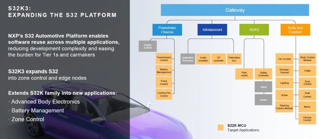
NXP (NXP Semiconductors) S32K series microcontrollers (MCUs) product portfolio and application fields. The S32K series is widely used in automotive electronic systems, providing different functionalities, safety levels, and performance to meet various demands.
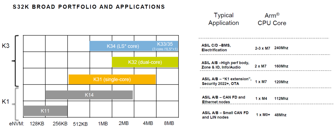
1. K1 Series:
- Application Scenarios: Mainly targeting the mid-to-low-end market, such as CAN FD, LIN node control, etc., with lower costs, suitable for mass applications.
- Core Features: Small storage capacity, low to medium performance, supports basic functional safety (ASIL A/B).
2. K3 Series:
- Application Scenarios: Targeting applications with high performance and high safety requirements, such as electrification, BMS, and high-performance body control.
- Core Features: Multi-core design, large storage capacity, high operating frequency, supports higher functional safety levels (ASIL C/D).
This product line’s wide coverage can meet the needs of automotive electronic systems with varying complexities and safety requirements, from simple sensor nodes to complex battery management systems.
2.2 Features of the S32K3 Platform
As shown in the figure, the features of NXP’s S32K3 platform and its packaging options are highlighted, emphasizing its excellent scalability.
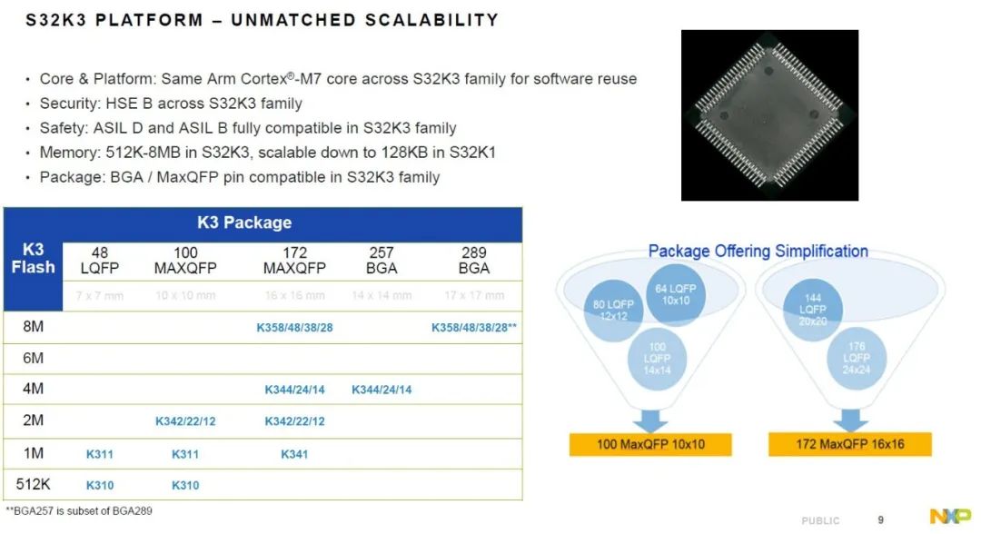
NXP’s S32K3 platform provides highly scalable and secure solutions for automotive and industrial applications through a unified Arm Cortex-M7 core, advanced security features (HSE B), comprehensive ASIL safety level support, and flexible memory configurations.
| ClassCategory | Description |
| Core and Platform | Using the same Arm Cortex®-M7 core, covering the entire S32K3 family, facilitating software reuse, reducing development time and costs. |
| Security | HSE B security module (Hardware Security Engine B) applied across the entire S32K3 family, providing hardware-level security protection. |
| Functional Safety | Supports ASIL D and ASIL B level functional safety standards, meeting the highest safety requirements in automotive electronic systems. |
| Memory Configuration | Memory ranges from 512KB to 8MB and is backward compatible with the S32K1 family of 128KB, ensuring flexible choice space. |
| Packaging Compatibility | Provides BGA (Ball Grid Array) and MaxQFP (Max Quad Flat Package), and is pin-compatible within the S32K3 family, simplifying hardware design. |
Additionally, through packaging simplification strategies, the complexity of design and manufacturing is further reduced, making it an ideal choice for multi-scenario applications.
NXP S32K3 series achieves excellent low-power performance while providing high performance through flexible operating modes and standby modes. Through the power estimation tool, developers can accurately assess energy consumption during the design phase, optimizing system configuration. These features make S32K3 an ideal choice for automotive and industrial applications that require a coexistence of high efficiency and low power consumption.
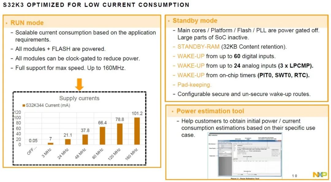
| Mode/Tools | Features/Functions |
| 1.RUN Mode(Running Mode) | |
| Scalable current consumption | Current consumption can be dynamically adjusted based on application needs, balancing performance and energy consumption. |
| All modules and flash powered | All hardware modules and internal flash are powered, ensuring the microcontroller fully performs its functions. |
| Clock gating | Reduces power consumption by turning off clock signals to inactive modules. |
| Maximum speed support | Supports operating speeds of up to 160MHz, providing strong processing power. |
| 2.Standby Mode(Standby Mode) | |
| Main core/platform/flash/PLL power off | Main core, platform module, flash, and phase-locked loop (PLL) power off, with most SoCs in an inactive state, significantly reducing power consumption. |
| STANDBY-RAM | Provides 32KB of standby memory, ensuring data retention in low-power state, reducing energy consumption from frequent wake-ups. |
| Wake-up function | |
| -Digital input wake-up | Supports up to 60 digital input signals to trigger wake-up. |
| -Analog input wake-up | Supports up to 24 analog inputs to trigger wake-up, including 3 low-power comparators (LPCMP). |
| -On-chip timer wake-up | Supports wake-up via on-chip timers like PIT0, SWT0, RTC, etc. |
| Pad-keeping | Maintains pin level status in standby mode, avoiding external circuit abnormalities. |
| Configurable secure/non-secure wake-up paths | Select secure or non-secure wake-up paths based on application scenarios to meet different safety needs. |
| 3.Power Estimation Tool(Power Estimation Tool) | |
| Initial power/current estimation | Provides initial power and current consumption estimates based on specific usage scenarios, optimizing system design and power management. |
| Tool interface display | The tool interface supports selecting MCUs, configuring parameters, and viewing power consumption results. Users can adjust frequency, peripheral enable states, and other parameters to simulate different scenarios. |
As shown in the figure, the communication interface characteristics of the NXP S32K3 series microcontrollers (MCUs) are highlighted.
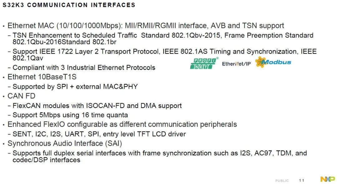
| Module/Interface | Characteristics/Functions |
| 1.Ethernet MAC (10/100/1000Mbps) | |
| Interface and Support | |
| -MII/RMII/RGMII interface | MII: 10/100Mbps; RMII: simplified version of MII; RGMII: 1Gbps. |
| -AVB and TSN support | AVB: Audio Video Bridging; TSN: enhances real-time performance and reliability. |
| TSN Enhanced Features | |
| -802.1Qbv-2015 | Deterministic transmission, time-slicing scheduling traffic. |
| -802.1Qbu-2016 | High-priority packets interrupt low-priority packets, reducing latency. |
| -802.1br | Bridging device port expansion, optimizing traffic management. |
| Protocol Support | |
| -IEEE 1722 | Audio video streaming transport protocol. |
| -IEEE 802.1AS | High-precision time synchronization, suitable for industrial automation and vehicle communication. |
| -IEEE 802.1Qav | Traffic shaping, reducing congestion, ensuring smooth audio and video transmission. |
| Industrial Ethernet Protocol Compatibility | Profinet, EtherNet/IP, Modbus, suitable for automation control and industrial device networking. |
| 2.Ethernet 10BaseT1S | |
| 10BaseT1S | Single-pair Ethernet standard, reducing wiring costs, supporting multi-node interconnections. |
| SPI+External MAC&PHY support | Collaborates with external MAC and PHY via SPI to achieve data transmission. |
| 3.CAN FD (Flexible Data-Rate CAN) | |
| FlexCAN module support | |
| -ISOCAN-FD | ISO-standard compliant CAN FD protocol, supports higher data transmission rates and larger data frames. |
| -DMA support | Direct Memory Access, reducing CPU load, enhancing efficiency. |
| Supports 5Mbps rate | Five times faster than traditional CAN, suitable for high-bandwidth demand scenarios. |
| 16 time quanta | Improving data transmission accuracy and time synchronization capability. |
| 4.Enhanced FlexIO | |
| FlexIO functionality | Configurable for various communication peripherals, providing hardware-level flexibility. |
| Supported Protocols | |
| -SENT | Single-edge nibble transmission protocol, suitable for sensor data transmission. |
| -I2C | Multi-master/slave serial communication protocol, suitable for short-distance device communication. |
| -I2S | Audio device serial bus protocol. |
| -UART | Universal Asynchronous Receiver-Transmitter, widely used in serial communication. |
| -SPI | High-speed synchronous serial communication protocol, suitable for short-distance high-speed data exchange. |
| Entry-level TFT LCD driver | Supports basic LCD display control to meet simple graphical display needs. |
| 5.Synchronous Audio Interface (SAI) | |
| Full-duplex serial interface | Simultaneously sends and receives data, improving communication efficiency. |
| Frame synchronization | Ensures synchronization of audio data streams, crucial for multi-channel audio transmission. |
| Supported Audio Protocols | |
| -I2S | Protocol designed for digital audio devices. |
| 0 | Audio codec standard commonly used in PC audio systems. |
| -TDM | Time Division Multiplexing, allowing multiple audio signals to be transmitted over the same line. |
| Codec/DSP Interface | Suitable for audio processors and digital signal processing units. |
The S32K3 series MCUs provide a rich set of communication interfaces, supporting everything from industrial Ethernet to high-bandwidth CAN FD, flexible multi-protocol FlexIO, and advanced audio interfaces, suitable for various scenarios in automotive, industrial automation, and embedded systems.
The S32K3 Ethernet IP module features extensive interface and rate support, combined with powerful TSN and AVB features, making it particularly suitable for applications requiring high real-time performance and determinism in automotive and industrial network scenarios. These features not only enhance network performance but also ensure data synchronization and traffic management in complex systems.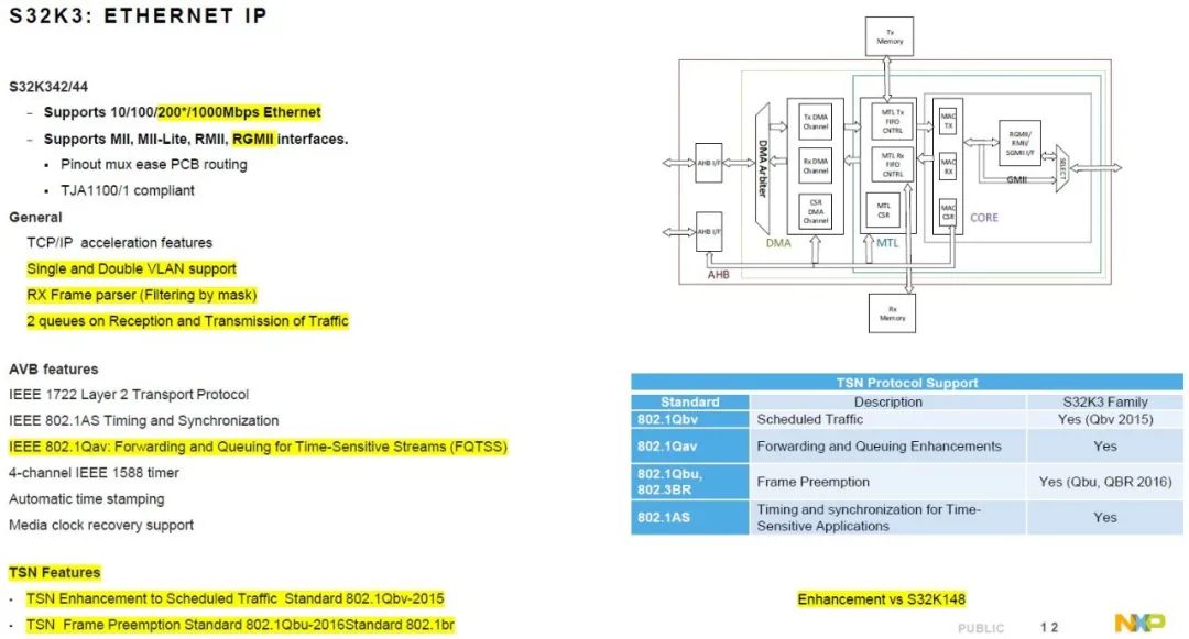
| Category/Feature | Description |
| 1.Basic Features(S32K342/344) | |
| Supported Rates | |
| -10/100/200*/1000 Mbps | 200 Mbps is special support, suitable for specific industrial or automotive application scenarios. |
| Interface Support | |
| -MII | Standard Media Independent Interface, supports 10/100Mbps. |
| -MII-Lite | Simplified version of MII, reducing costs or complexity. |
| -RMII | Reduces pin count, enhancing hardware design flexibility. |
| -RGMII | Supports Gigabit Ethernet, fewer pins, suitable for high-bandwidth applications. |
| Hardware Compatibility | |
| -Pin multiplexing design | Simplifies PCB wiring. |
| -Compatible with TJA1100/1 | Compatible with NXP’s automotive Ethernet PHY transceivers, ensuring compatibility in automotive networks. |
| 2.General Features(General) | |
| TCP/IP acceleration function | Hardware-level acceleration processing, reducing CPU load, improving network transmission efficiency. |
| VLAN Support | |
| -Single-layer VLAN | Applicable for network segmentation and isolation. |
| -Double-layer VLAN (Q-in-Q) | Commonly used in service provider networks, distinguishing different customers’ data flows. |
| RX Frame Parser | Filters and selects received data packets through masking, improving data processing efficiency. |
| Dual Queue Management | Each has two queues for receiving and sending, optimizing network traffic management. |
| 3.AVBFeatures(Audio Video Bridging) | |
| IEEE 1722 | Layer 2 transmission protocol defining audio and video data transmission over Ethernet. |
| IEEE 802.1AS | Timing and synchronization protocol ensuring device clock consistency, core foundation for AVB and TSN. |
| IEEE 802.1Qav | Time-sensitive stream (FQTSS) forwarding and queuing, ensuring important packets are prioritized for transmission, reducing latency and packet loss. |
| 4-channel IEEE 1588 timing | Provides precise time synchronization, suitable for high-demand industrial control and audio-video synchronization applications. |
| Automatic timestamping and media clock recovery | Ensures accurate time marking of data packets, enhancing audio-video playback synchronization and consistency. |
| 4.TSNFeatures(Time-Sensitive Networking) | |
| TSN Enhanced Features | |
| -Scheduled traffic enhancement (802.1Qbv-2015) | Precise control of Ethernet frame transmission time, ensuring high-priority packets are sent at predetermined times. |
| -Frame preemption standard (802.1Qbu, 802.1BR) | Allows high-priority frames to interrupt low-priority frames, improving real-time performance and response speed. |
The FlexCAN module provides powerful CAN bus communication capabilities, supporting everything from standard CAN 2.0 to high-performance CAN FD protocols. Its protocol engine can automatically handle errors and message verification, and the embedded RAM provides efficient message buffer management, supporting multi-instance operation to meet the communication needs of complex systems. Its flexibility and high reliability make it widely applicable in automotive electronics and industrial control fields. 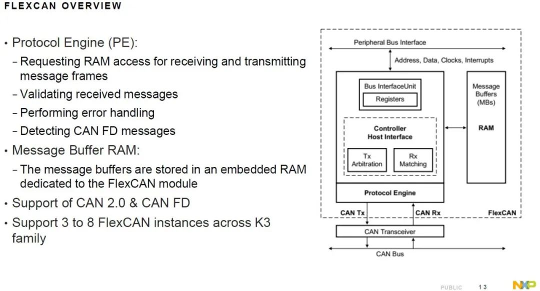
| Module/Function | Description |
| Protocol Engine (PE) | |
| Requests RAM access to receive and send message frames | The protocol engine requests read/write permissions to the embedded RAM via the bus interface to receive and send CAN message frames. Each message frame needs to be stored in a specific buffer in RAM, and the PE controls the read/write of these buffers. |
| Validates received messages | When a message is received on the CAN bus, the PE performs integrity checks on the data, such as CRC checks, to ensure the data has not been corrupted during transmission. |
| Executes error handling | The protocol engine can detect and handle common CAN network errors, such as bit errors, stuffing errors, ACK errors, etc. It can also automatically perform error recovery to maintain stable operation of the bus. |
| Detects CAN FD messages | The protocol engine can distinguish between standard CAN 2.0 messages and CAN FD (Flexible Data-rate) messages. CAN FD allows for larger data payloads and faster transmission rates, and the PE can automatically adapt to different protocols. |
| Message Buffer RAM | |
| Storage of message buffers | Each message buffer (Message Buffer, MB) is used to store a complete CAN message, including ID, data, control information, etc. The FlexCAN module has multiple such buffers, supporting parallel processing of multiple messages, enhancing the system’s response speed and reliability. |
| CAN Protocol Support | |
| Supports CAN 2.0 and CAN FD | The FlexCAN module is compatible with the traditional CAN 2.0 protocol (standard frame format and extended frame format), while also supporting the more efficient CAN FD protocol, meeting the needs for higher data transmission rates and data volumes, adapting to modern automotive and industrial system requirements. |
| Multi-instance Support | |
| Supports 3 to 8 FlexCAN instances | <spanin (or="" (such="" 3="" 8="" adas="" and="" architectures,="" as="" between="" body="" can="" channels).="" chips,="" communication="" complex="" control="" control,="" different="" flexcan="" for="" in="" independent="" instances="" k3="" means="" modern="" module="" multi-network="" multiple="" networks,="" powertrain,="" run="" series="" simultaneously="" span="" such="" suitable="" supports="" system="" systems). |
As shown in the figure, the characteristics comparison of the FlexCAN module in the S32K344 microcontroller covers the functionalities from FlexCAN0 to FlexCAN5.
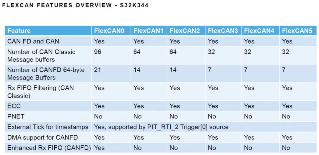
- FlexCAN0 is the most comprehensive module, with the most message buffers, the most CAN FD buffers, and supports enhanced receive FIFO, suitable for complex application scenarios with high data processing requirements.
- FlexCAN1 and FlexCAN2 are slightly less capable in message buffering and CAN FD support but are still suitable for medium-complexity applications.
- FlexCAN3, FlexCAN4, FlexCAN5 have relatively simplified functions, suitable for scenarios with lower communication bandwidth and buffering requirements.
As shown in the figure, the differences in the FlexCAN modules between the K3 and K1 versions in the S32K1 series are presented. 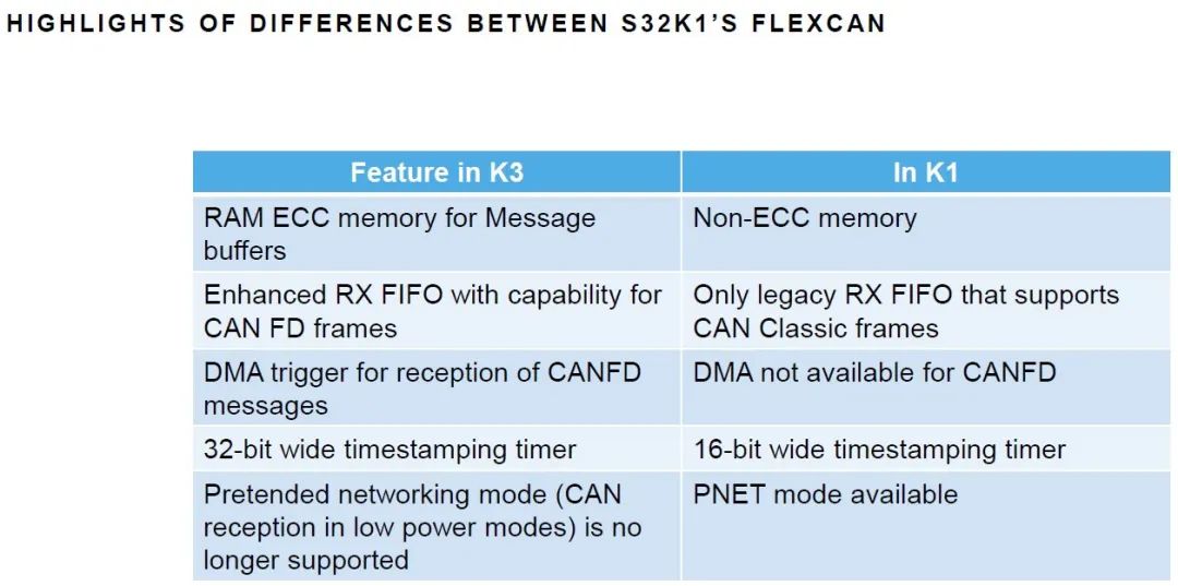
- K3 version of the FlexCAN module overall performance is stronger, especially in data transmission rate, time synchronization accuracy, and error detection, suitable for high-reliability and high-performance application scenarios, such as autonomous driving and complex industrial control systems.
- K1 version performs better in power consumption control, suitable for applications with low power requirements but not high performance demands, such as simple in-vehicle control systems or industrial automation devices.
As shown in the figure, an overview of NXP’s FlexIO module is presented, covering its features, configurations, and emulatable interfaces.
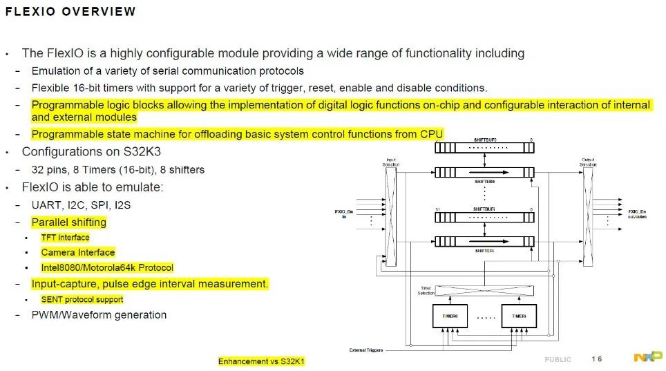
| Module/Function | Description |
| FlexIO Module Overview | |
| Emulation of various serial communication protocols | FlexIO can simulate common serial communication protocols such as UART, I2C, SPI, and I2S. This means that even without these interfaces in hardware, communication can be achieved through FlexIO. |
| Flexible 16-bit timer | FlexIO provides a 16-bit timer supporting various trigger, reset, enable, and disable conditions, allowing users to flexibly configure timer behavior based on needs. |
| Programmable logic block (Highlighted) | Allows the implementation of digital logic functions on-chip and configuration of interactions between internal and external modules. This is similar to embedding small FPGA functionality within the MCU, greatly enhancing flexibility and scalability. |
| Programmable state machine (Highlighted) | Used to offload basic system control functions from the CPU. This means that certain simple logical judgments and control tasks can be handled by FlexIO, reducing CPU load and improving overall system performance. |
| Configuration on S32K3 | |
| 32 pins | These pins can be used as inputs or outputs, providing high flexibility. |
| 8 16-bit timers | Each timer can be configured individually for various timing tasks. |
| 8 shift registers (Shifters) | Used for data shifting operations, core to implementing serial communication and parallel data processing. |
| FlexIO Emulatable Functions | |
| Emulation of serial communication interfaces | UART, I2C, SPI, I2S |
| Parallel shifting (Highlighted) | FlexIO can simulate parallel data shifting, suitable for applications requiring high-speed data transmission, such as TFT interfaces, camera interfaces, Intel 8080/Motorola 64k protocols. |
| Input capture, pulse edge interval measurement (Highlighted) | This allows FlexIO to capture changes in external signals and measure time intervals between pulses, suitable for applications requiring precise timing measurements. |
| SENT protocol support | SENT (Single Edge Nibble Transmission) is a commonly used single-edge communication protocol for automotive sensors, and FlexIO can directly support such protocols. |
| PWM/Waveform generation | FlexIO can also be used to generate PWM signals or other complex waveforms, suitable for motor control, LED dimming, etc. |
| Enhancements vs S32K1 | |
| Functional enhancements | FlexIO on S32K3 has significantly improved functions compared to S32K1, specific improvements may include more pins, higher flexibility, stronger protocol support, etc. |
The FlexIO module is a powerful and flexible functional module that can greatly expand the peripheral functionality of microcontrollers. Through programmable logic blocks and state machines, it can offload CPU tasks, implement various communication protocols and data processing, suitable for embedded systems, automotive electronics, industrial control, and various scenarios. Compared to S32K1, the FlexIO module of S32K3 provides more resources and stronger functionality, further enhancing the flexibility of system design.
#03Support for Multiple Instance Demonstration
3.1 Motor Control
As shown in the figure, the architecture and working principle of the NXP TSN (Time-Sensitive Networking) Motor Control Demonstration highlight the key technologies for achieving real-time motor control in an Ethernet environment.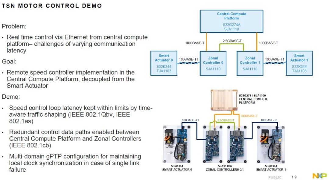
| Module/Function | Description |
| Problem Description | |
| Challenges in real-time control | When performing real-time motor control through Ethernet on a central computing platform, there are challenges related to communication delay fluctuations. This is because Ethernet is inherently non-deterministic, and network delays can fluctuate due to changes in data traffic, topology, and physical link quality, posing challenges for real-time control. |
| Goal | |
| Implementation of remote speed controller | Placing the speed controller’s functionality on the central computing platform rather than directly integrating it into smart actuators. The advantage of this decoupled design is that it can centralize computing resources, simplify actuator complexity, reduce costs, while enhancing system flexibility and maintainability. |
| Demonstration Details | |
| Keep speed control loop delay within controllable range | By employing time-sensitive networking (TSN) technology for time-aware traffic shaping, ensure that the speed control loop’s delay remains within acceptable limits. |
| Key Standards | IEEE 802.1Qbv: Defines time-aware scheduling to ensure that critical traffic is transmitted within specific time windows, thereby reducing delay fluctuations. |
| IEEE 802.1AS: Provides precise time synchronization protocols to ensure that devices across the network remain synchronized, further reducing delays caused by time desynchronization. | |
| Enable redundant control data paths | To enhance system reliability, the demonstration system designs redundant control data paths, meaning there are multiple paths for transmitting control data between the central computing platform and the zonal controllers. |
| Key Standards | IEEE 802.1CB: Provides frame replication and elimination technology, ensuring that even if one link fails, another link can still transmit data normally, guaranteeing the reliability of control signals. |
| Multi-domain gPTP Configuration | Uses multi-domain General Precision Time Protocol (gPTP) to maintain synchronization of local clocks, ensuring consistency in system time even in the case of a single link failure. |
| gPTP is a core part of the TSN architecture, ensuring that all devices operate under the same time reference, which is crucial for real-time control systems. | |
| System Architecture Analysis | |
| Core Hardware Components | |
| Central Computing Platform | Device: S32G274A (main processor), SJA1110 (Ethernet switch) |
| Function: Responsible for running remote speed control algorithms, centrally processing data from all sensors and actuators. | |
| Interface: 2.5GBASE-T: Communicates with Zonal Controllers 0/1, providing high-speed data transmission. | |
| 1000BASE-T: Communicates with other devices or system modules via Gigabit Ethernet. | |
| Zonal Controllers (Zonal Controllers 0/1) | Device: SJA1110 (Ethernet switch) |
| Function: Acts as an intermediate control layer, responsible for forwarding control commands from the central computing platform to smart actuators while aggregating feedback data from actuators. | |
| Interface: 2.5GBASE-T: Connects to the central computing platform, ensuring high-speed low-latency communication. | |
| 100BASE-T1: Connects to smart actuators, transmitting control commands and status data. | |
| Smart Actuators (Smart Actuators 0/1) | Device: S32K344 (microcontroller), TJA1103 (Ethernet PHY) |
| Function: Directly controls the operation of motors, but the control algorithm runs on the central computing platform, with the actuator itself only executing commands and providing feedback. | |
| Interface: 100BASE-T1: Communicates with zonal controllers, ensuring the real-time and accuracy of data flow. | |
| Network Topology and Connection Description | |
| Central Computing Platform | Connects to Zonal Controllers 0 and 1 via 2.5GBASE-T links, ensuring high-speed communication. |
| Smart Actuators | Smart Actuator 0 and Smart Actuator 1 connect to Zonal Controllers 0 and 1 respectively via 100BASE-T1 links. |
| Other System Modules | The central computing platform connects to other system modules (such as upper computers or monitoring systems) via 1000BASE-T links, ensuring data transmission integrity and system expansion capability. |
3.2 5G T-BOX
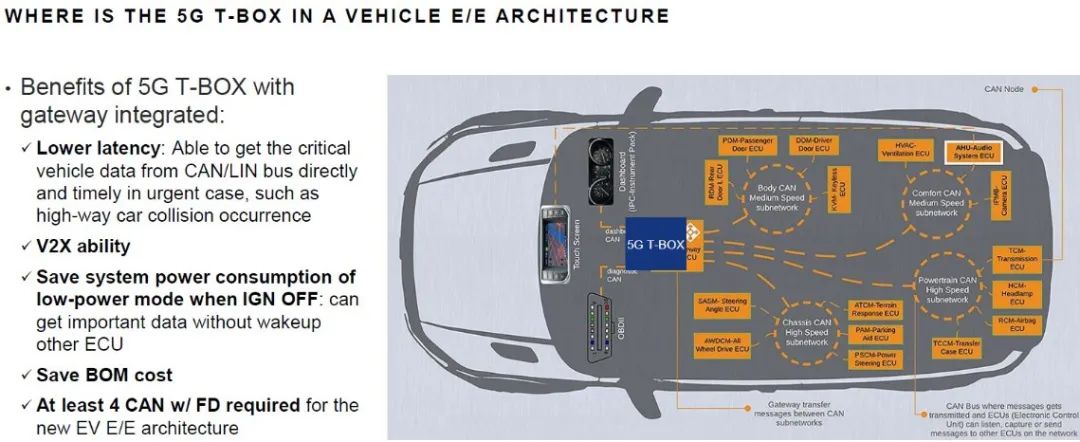
As shown in the figure, the position of the 5G T-BOX in the automotive electronic electrical (E/E) architecture and its advantages of integrating gateways are illustrated.
1. Definition and Position of 5G T-BOX
- 5G T-BOX: This is an in-vehicle remote information processing unit that supports 5G communication. It is typically integrated near the vehicle’s central control module for direct interaction with other electronic control units (ECUs) and in-vehicle bus systems (such as CAN/LIN bus).
- Position in the figure: The 5G T-BOX is located in the lower central area of the vehicle’s front row, close to the dashboard and touchscreen. This position facilitates quick access to critical data from various sub-networks.
2. Advantages of 5G T-BOX with Integrated Gateway
| Function/Feature | Description |
| Lower Latency | |
| Directly obtaining critical vehicle data | The 5G T-BOX can directly obtain critical vehicle data from the CAN/LIN bus without the need for an intermediary layer for forwarding. |
| Quick response in emergencies | In emergencies (such as accidents on highways), data can be quickly obtained and processed, improving response speed. |
| V2X Capability | |
| V2X (Vehicle-to-Everything) | Refers to the communication capability between the vehicle and the external environment (such as other vehicles, infrastructure, pedestrians, etc.). The 5G T-BOX supports V2X functionality, enhancing the level of vehicle networking technology, contributing to intelligent transportation systems and autonomous driving development. |
| Save System Power Consumption in Low-Power Mode when Ignition OFF | |
| Low-power mode | After the vehicle is turned off (IGN OFF), the 5G T-BOX can still obtain important data in low-power mode without waking up other ECUs. This reduces the overall system energy consumption and extends battery life. |
| Reduce BOM Cost | |
| BOM (Bill of Materials) | After integrating the gateway functionality, the 5G T-BOX can reduce the demand for separate gateway devices, thereby lowering the hardware costs of the entire vehicle. |
| At least 4 CAN with FD required | |
| New electronic electrical architecture for electric vehicles requires | At least 4 CAN buses with flexible data rates (FD) to support high-speed, efficient data transmission. The 5G T-BOX must be compatible with these buses to ensure stable communication performance. |
As shown in the figure, the hardware architecture of the 5G T-BOX covers its communication interfaces, key modules, and their functions.
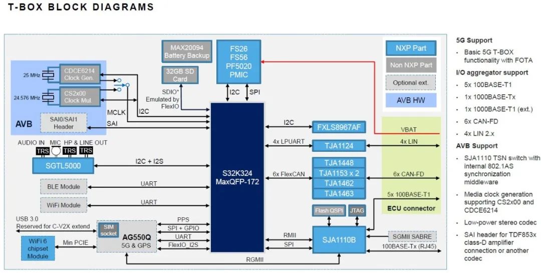
| Module/Function | Description |
| Core Processor and Main Modules | |
| S32K324 (MaxQFP-172) | This is NXP’s 32-bit automotive-grade MCU responsible for the main control tasks of the T-BOX. |
| Interface Support | I2C: Connects to sensors (such as FXLS8967AF) and power management chips (PMIC). |
| SPI: Communicates with power management (PMIC) and TSN switches (SJA1110B). | |
| UART: Connects to Bluetooth modules, WiFi modules, and other communication modules. | |
| 6 FlexCAN: Supports multiple CAN-FD (Flexible Data Rate CAN) for communication with various in-vehicle subsystems. | |
| 4 LIN: Low-speed LAN interface for simple control tasks. | |
| RGMII: Gigabit Ethernet interface, connects to the SJA1110B switch, supporting high-speed data transmission. | |
| JTAG: For debugging and programming. | |
| Communication and Expansion Module | |
| AG550Q (5G&GPS Module) | Integrates 5G communication and GPS positioning, providing high-speed wireless connectivity. |
| Interface | SIM card slot: For 5G network connection. |
| SPI+GPIO, UART, I2O_I2S: For communication with the main control chip. | |
| Mini PCIE: Expansion interface for connecting WiFi 6 chip modules. | |
| WiFi Module&BLE Module | WiFi Module: Supports wireless network communication inside and outside the vehicle. |
| BLE Module: Low-power Bluetooth for short-range communication between in-vehicle devices. | |
| Interface | All connected via UART to S32K324. |
| USB 3.0 Interface | Reserved for use: For C-V2X (Car-to-Everything) expansion, enabling direct communication with external devices or infrastructure. |
| Audio and Clock Module | |
| SGTL5000 (Low-Power Stereo Audio Codec) | Handles in-vehicle audio input and output. |
| Interface | I2C+I2S: For communication with the main control chip. |
| AUDIO IN/MIC/HP&LINE OUT: Audio input, microphone input, and headphone/line output interfaces. | |
| Clock Generation and Synchronization Module | CDCE6214 (Clock Generator)& CS2x00 (Clock Multiplier): Provides stable system clock signals, supporting precise time synchronization. |
| Output signals for use by AVB module and main control chip. | |
| SAI0/SAI1 Header: For connecting TDF853x class D amplifiers or other codecs, supporting audio video bridging (AVB). | |
| Sensors and Power Management | |
| FXLS8967AF (Three-Axis Accelerometer) | Used to detect vehicle acceleration and collision data. |
| Interface | Connected via I2C to the main control chip. |
| Power Management Module (PMIC) | FS26, FS56, PF5020: Responsible for supplying power to various modules of the T-BOX, providing stable power management. |
| Communicates with the main control chip via SPI, supporting power status monitoring and control. | |
| MAX20094 (Battery Backup) | Provides backup power, ensuring the T-BOX can operate normally in the event of a power outage, especially maintaining data transmission capabilities during emergencies. |
| Network and AVB Support | |
| SJA1110B (TSN Switch) | Time-sensitive networking (TSN) switch, supporting IEEE 802.1AS time synchronization protocol, ensuring precise synchronization among different devices in the vehicle network. |
| Interface | RMII: Ethernet connection to the main control chip. |
| SPI: For data communication. | |
| Flash QSPI: For firmware storage. | |
| JTAG: For debugging. | |
| ECU Connector | Interface supports: 5x 100BASE-T1: In-vehicle Ethernet interface for high-speed data transmission. |
| 6x CAN-FD: Flexible data rate CAN interface for high-speed communication among different ECUs in the vehicle. | |
| 4x LIN 2.x: Low-speed LAN interface for simple device control. | |
| 100BASE-Tx (RJ45): Standard Ethernet interface for connecting external devices. |
The T-BOX architecture diagram showcases its strong 5G communication, V2X expansion capabilities, multi-channel CAN-FD, and Ethernet support, integrating rich interfaces and modules to meet modern automotive demands for high-speed, stable communication and multimedia processing. The T-BOX is not only a core component of vehicle networking but also a crucial infrastructure for achieving autonomous driving, remote diagnostics, and in-vehicle intelligence.
3.3 S32K Multi-Network Synchronization Demonstration
As shown in the figure, the content of the S32K multi-network synchronization demonstration includes technical challenges, key features and advantages of the demonstration, as well as system architecture diagrams.
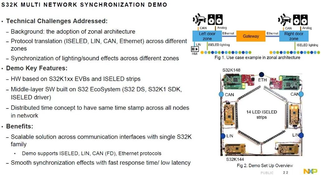
| CategoryDescription | Description |
| Technical Challenges | |
| Background of adopting zonal architecture | The automotive electronic system is transitioning from a traditional domain control architecture to a zonal architecture (Zonal Architecture), segmenting the vehicle into different physical areas (such as door areas) and using centralized gateways for management, helping to reduce harness length and improve system modularity. |
| Protocol conversion across zones | Communication between different zones requires conversion of various protocols, such as ISELED (intelligent LED control), LIN (Local Interconnect Network), CAN (Controller Area Network), and Ethernet, ensuring correct data transmission between different zones is a major challenge. |
| Synchronization of lighting/sound effects | Lighting and sound in different zones need to be precisely synchronized, such as ambient light gradients and multi-speaker audio coordination, requiring the system to possess high-precision time synchronization mechanisms to avoid delays or misalignment. |
| Key Features of the Demonstration | |
| Hardware Foundation | The demonstration system is based on the S32K1xx evaluation boards (EVBs) and ISELED light strips, where the S32K1xx series is NXP’s 32-bit ARM Cortex-M microcontroller widely used in automotive electronics. |
| Middleware Software | The software is based on the NXP S32 ecosystem, including: S32 DS (development environment), S32K1 SDK (software development kit), and ISELED driver (to control ISELED light strips). |
| Distributed Time Concept | Introduces the concept of distributed time synchronization, ensuring all network nodes share the same timestamp, achieving highly synchronized control. |
| Advantages | |
| Scalable solution | A single S32K series microcontroller supports multiple communication interfaces, with high scalability and flexibility. |
| Supported Protocols | Supports ISELED, LIN, CAN FD (Flexible Data Rate Controller Area Network), and Ethernet. |
| Smooth synchronization effects | The system provides fast response and low-latency synchronization effects, ensuring smooth and natural transitions and changes in lighting and sound. |
This demonstration showcases how to utilize the NXP S32K platform to achieve seamless conversion among multiple protocols and high-precision synchronization of lighting/sound under a zonal architecture. It not only addresses the technical challenges of cross-protocol communication and time synchronization but also provides efficient and scalable solutions to meet the complex demands of modern automotive electronic systems.
Based on ISELED and Ethernet AVB, the Smart Door Zone Solution is introduced.
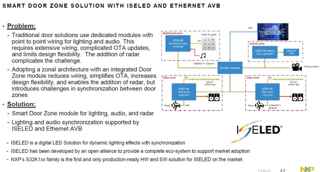
| CategoryContent | Content |
| Problem | |
| Limitations of Traditional Door Solutions | |
| Point-to-point wiring complexity | –Complex and lengthy wiring: Increases the complexity and weight of the vehicle’s internal harness. |
| –OTA updates complexity: Each module operates independently, requiring separate handling during updates, increasing maintenance difficulty. | |
| –Design flexibility limitations: Each module has fixed functions, making it difficult to flexibly adjust system configurations based on needs. | |
| Complexity of Integrating Radar Functions | With the development of ADAS, radar sensors have been added to the door system, further complicating wiring and module coordination. |
| Challenges of Adopting Zonal Architecture | –Reduced wiring but complex synchronization: The zonal architecture reduces harness length through integrated door area modules, simplifies OTA updates, increases design flexibility, and supports radar integration. However, it brings synchronization challenges between different door areas, especially in coordinating lighting and sound effects. |
| Solution | |
| Smart Door Area Module | This module integrates lighting, audio, and radar functions, simplifying wiring and providing greater system flexibility. |
| Synchronization of Lighting and Sound Based on ISELED and Ethernet AVB | –ISELED: Provides dynamic lighting effects and precise synchronization, ensuring consistent and smooth changes in in-vehicle ambient lighting. |
| –Ethernet AVB: Achieves low-latency, high-precision synchronization of audio and video data through Ethernet, ensuring coordinated sound effects in multi-speaker systems. | |
| ISELED Technology Features | |
| Dynamic Lighting Effect Synchronization | ISELED is a digital LED solution for synchronizing dynamic lighting effects, capable of precise control of in-vehicle ambient lighting and multi-zone synchronization, enhancing the driving experience. |
| Open Alliance Development | ISELED is developed by an open alliance, providing a complete ecosystem to support market applications, covering hardware, software, and system integration. |
| NXP’s S32K1xx Series | NXP’s S32K1xx series is the first and only mass-produced ISELED hardware and software solution on the market, designed specifically for automotive applications, providing support for ISELED and Ethernet AVB, and serving as the core hardware for achieving intelligent door zone control. |
This solution demonstrates how to achieve efficient integration and synchronization of lighting, audio, and radar functions in smart door zones through NXP’s S32K1xx series microcontrollers and ISELED technology. It not only addresses the wiring and synchronization challenges of traditional systems but also provides robust support for the flexibility and scalability of future automotive electronic systems. #04Conclusion
The S32K3 series microcontrollers provide efficient and reliable solutions for modern automotive zonal architectures with their rich communication interfaces, low power performance, and excellent anti-interference capabilities. Coupled with various practical application demonstrations, the S32K3 not only accelerates product development but also provides a solid foundation for upgrading and innovating vehicle electronic systems. This series of products is particularly suitable for applications in intelligent doors, cabin control, ambient light synchronization, and ADAS systems, serving as an important technical support for the future development of smart vehicles.
References:
-
NXP S32K3 Domain Controller Application Introduction | NXP Semiconductors
/ END /