This introductory article is used for internal team training and has been publicly released after some content has been omitted.
Author: twowinter. Please credit the author when reproducing this article.
This article is a popular science introduction to LoRaWAN. You have seen countless superficial LoRaWAN articles in your social circles, and it’s time to dive into some real technical insights. This article first provides a horizontal overview of the forces behind LoRaWAN and its network deployment, and then elaborates vertically on the network architecture and specific protocol content, helping LoRa practitioners systematically understand the LoRaWAN protocol.
1. What is LoRaWAN?
According to the official white paper by the LoRa Alliance titled “What is LoRaWAN”, LoRaWAN is a communication protocol and system architecture designed for LoRa long-range communication networks.
LoRaWAN defines the communication protocol and system architecture for the network while the LoRa physical layer enables the long-range communication link.
Additionally, the official document provides this slightly technical protocol hierarchy diagram for everyone to get a general feel.
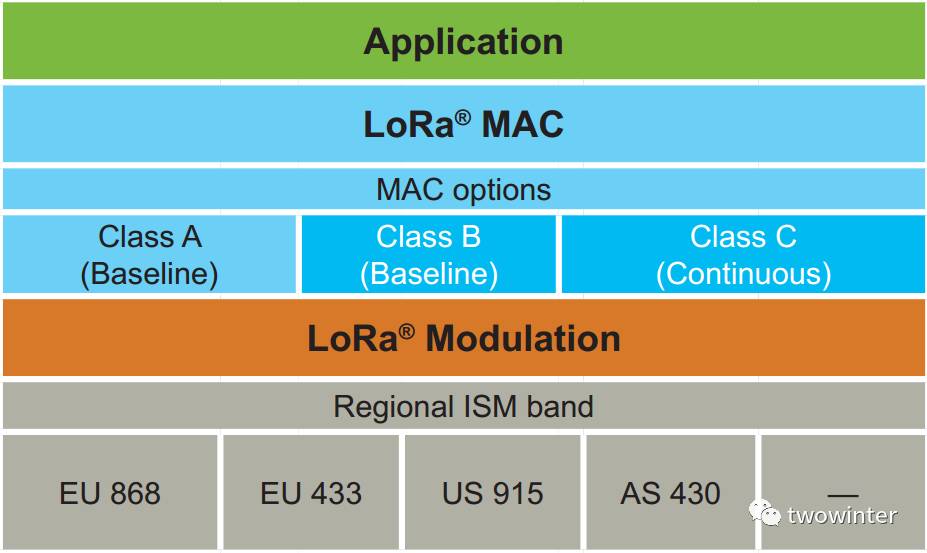
In the design of the protocol and network architecture, LoRaWAN fully considers factors such as node power consumption, network capacity, QoS, security, and the diversity of network applications. The following content will provide a deeper understanding of the introductory paragraph.
2. The Interest Groups Behind LoRaWAN — LoRa Alliance
In contrast to the well-established NB-IoT from the global standards organization 3GPP, the LoRa Alliance, which is behind LoRa, has a somewhat weaker influence. The cover of the protocol shows that the authors are from three board member companies: N. Sornin (Semtech), M. Luis (Semtech), T. Eirich (IBM), T. Kramp (IBM), O.Hersent (Actility).
We know that the promotion of every technology is accompanied by the drive of interests. Although organizations and alliances are non-profit organizations, their member companies do not solely focus on public welfare. From a business perspective, spending $50,000 on an investment is bound to be aimed at leveraging at least $500,000 in returns.
The LoRa Alliance was co-founded in the first half of 2015 by several manufacturers including Cisco, IBM, and Semtech. As of now (April 2017), there are over 400 members, including many large enterprises among the board members, all working together to share the future low-power wide-area network cake. I made a table collecting 19 board members willing to pay a $50,000 membership fee; you can see the aspirations of these companies.
|
Telecom Operators |
bouygues |
One of the three major mobile network operators in France |
|
comcast |
The largest cable operator in the United States |
|
|
KPN |
Royal KPN Telecom Group |
|
|
orange |
Telecom operator in France |
|
|
Proximus |
Telecom operator in Belgium |
|
|
SK telecom |
Telecom operator in South Korea |
|
|
Network Security Solution Provider |
gemalto |
Gemalto, a network security solution provider involved in network encryption design, is a partner of China Mobile |
|
giesecke |
Giesecke, a payment security solution provider involved in network encryption design, is a supplier for ICBC, CCB, etc. |
|
|
Cloud Platform Solution Provider |
actility |
France, ThingPark cloud platform |
|
IBM |
Platform solution provider |
|
|
ZTE |
ZTE, platform solution provider, base station solution provider |
|
|
Base Station Solution Provider |
cisco |
Cisco |
|
kerlink |
Base station solution provider |
|
|
sagemcom |
Base station solution provider |
|
|
Terminal Chip Solution Provider |
semtech |
Supplier of LoRa RF chips |
|
ST |
Microcontroller supplier |
|
|
renesas |
Renesas, microcontroller supplier |
|
|
Industry Application Solution Provider |
flashnet |
Energy management application provider, such as smart streetlights |
|
homerider |
Water meter application provider |
3. Network Deployment Situation of LoRaWAN
After binding with several major telecom operators, the network deployment situation becomes quite promising. According to the official statement as of now (April 2017), the network deployment situation is as follows:
34 publicly declared deployed networks, with at least 150 ongoing city pilot deployments.
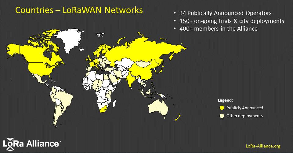
Have you noticed the little white spot on the chicken neck? It may be due to the brilliance of subjectivism shining too bright.
4. LoRaWAN Network Architecture
Having learned that LoRaWAN is very popular, let’s delve into the technical aspects. Below is the network architecture diagram from the official white paper of the LoRa Alliance.
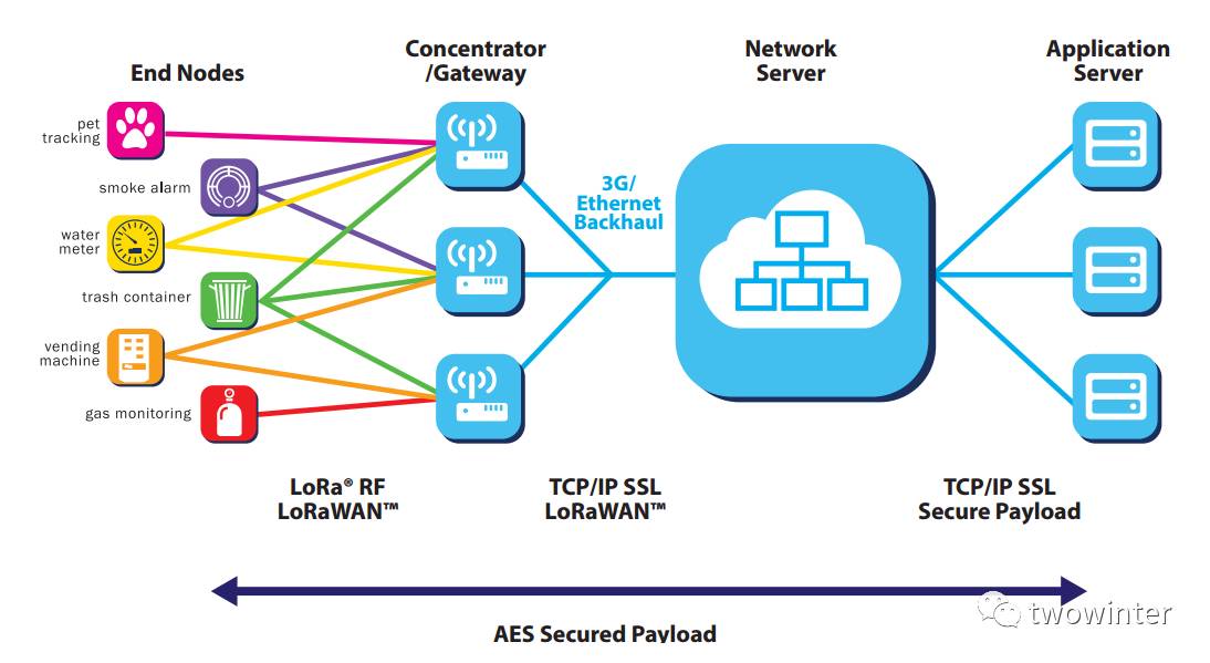
In a LoRaWAN network architecture, there are four components: terminal, base station, NS (network server), and application server. The topology between the base station and terminal is star-shaped, and due to the long-distance characteristics of LoRa, they can communicate using single-hop transmission. In the terminal section, the official document lists six typical applications. A detail to note is that terminal nodes can send data to multiple base stations simultaneously. The base station processes and forwards the LoRaWAN protocol data between NS and terminals, carrying LoRaWAN data on both LoRa RF transmission and TCP/IP.
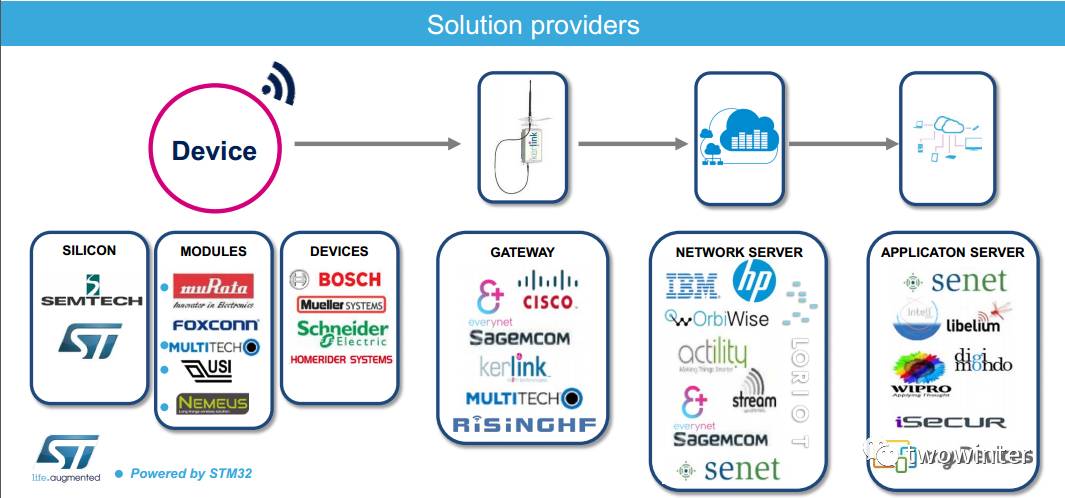
Next, let’s look at this network architecture in conjunction with the industry ecosystem for a deeper understanding. The diagram is from ST’s LoRa white paper “IoT connectivity made easier STM32 MCUs & LoRa”.
5. Protocol Overview
5.1 Classification of Terminal Nodes
In the introduction, we saw that the protocol specifies three classes of terminal devices: Class A/B/C, which basically cover all application scenarios in the Internet of Things.
To facilitate understanding, I have created a table.
|
CLASS |
Description |
Downlink Timing |
Application Scenarios |
|
A (“all”) |
Class A terminals use the ALOHA protocol to report data on demand. After each uplink, two short downlink reception windows immediately follow to achieve bidirectional transmission. This operation is the most power-efficient. |
Must wait for the terminal to report data before sending downlink data. |
Bin monitoring, smoke detectors, gas monitoring, etc. |
|
B (“beacon”) |
Class B terminals, in addition to Class A’s random reception window, will open reception windows at specified times. To enable terminals to open reception windows at specified times, they need to receive time-synchronized beacons from the gateway. |
Can send downlink data during fixed reception windows, with some delay. |
Valve-controlled water, gas, and electricity meters, etc. |
|
C (“continuous”) |
Class C terminals are basically always open to receiving windows, only briefly closing during transmission. Class C terminals consume more power than Class A and Class B. |
Can send downlink data at any time since the terminal is in a continuous receiving state. |
Streetlight control, etc. |
5.2 Uplink and Downlink Transmission of Terminal Nodes
Now let’s look at some timing diagrams for a deeper understanding.
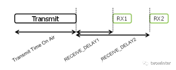
This is the timing diagram for Class A uplink and downlink. Currently, the RX1 reception window generally starts 1 second after the uplink, and the RX2 reception window starts 2 seconds after the uplink.
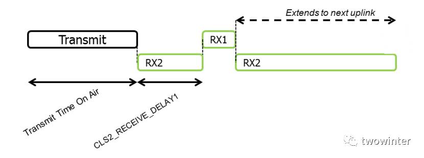
Class C is similar to A, except that during Class A’s sleep period, it keeps the RX2 reception window open.
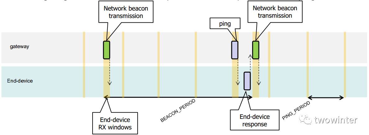
Class B’s timing is a bit more complex, with a synchronization time slot beacon and a fixed-cycle reception window ping time slot. In this example, the beacon period is 128 seconds, and the ping period is 32 seconds.
5.3 Network Joining of Terminal Nodes
After understanding the basic concepts, we can learn how nodes operate. Before formally sending and receiving data, terminals must first join the network.
There are two joining methods: Over-the-Air Activation (OTAA) and Activation by Personalization (ABP).
Commercial LoRaWAN networks generally follow the OTAA activation process to ensure security. This method requires three parameters: DevEUI, AppEUI, and AppKey.
DevEUI is a globally unique ID similar to IEEE EUI64 that identifies a unique terminal device, akin to a device’s MAC address.
AppEUI is a globally unique ID similar to IEEE EUI64 that identifies a unique application provider. For example, each garbage monitoring application, smoke detector application, etc., has its unique ID.
AppKey is assigned to the terminal by the application owner.
After initiating the joining process, the terminal sends a join command, and if the NS (network server) confirms it is correct, it will reply to the terminal, assigning a network address DevAddr (32-bit ID). Both parties use the information in the join reply along with AppKey to generate session keys NwkSKey and AppSKey for data encryption and verification.
If the second joining method, ABP activation, is used, it is simpler and more straightforward, directly configuring the three final communication parameters for LoRaWAN: DevAddr, NwkSKey, and AppSKey, without requiring the join process. In this case, the device can directly send application data.
5.4 Data Transmission and Reception
After joining the network, application data is encrypted.
As mentioned in the introduction, one major consideration in the design of LoRaWAN is to support application diversity. In addition to using AppEUI to classify applications, FPort application ports can also be used to handle data separately during transmission. The range of FPort values is (1~223), specified by the application layer.
5.5 ADR Mechanism
We know that in LoRa modulation, there is the concept of spreading factors, and different spreading factors will have different transmission distances and rates, which do not affect each other.
To expand the capacity of the LoRaWAN network, the protocol has designed a LoRa Adaptive Data Rate (ADR) mechanism, where devices at different transmission distances will, according to transmission conditions, use the fastest data rate possible. This also makes overall data transmission more efficient.
5.6 MAC Commands
For network management needs, the protocol has designed a series of MAC commands to modify network-related parameters, such as reception window delays, device rates, etc. In practical applications, these are generally seldom involved, so we will not cover them for now.
6. Regional Parameters
In addition to the protocol, the LoRa Alliance has released a supplementary document titled “LoRaWAN Regional Parameters”, which describes the specific parameters of LoRaWAN in different regions worldwide. To avoid changes to the document due to the addition of new regions, the regional parameters section has been separated from the protocol specification.
This document mainly discusses the specific physical layer parameters of LoRaWAN in various regions globally, noting that not only frequency bands differ, but also details such as channel divisions, data rates, transmission power, maximum data lengths, etc., vary.
To help everyone understand the overall situation, I have created a table.
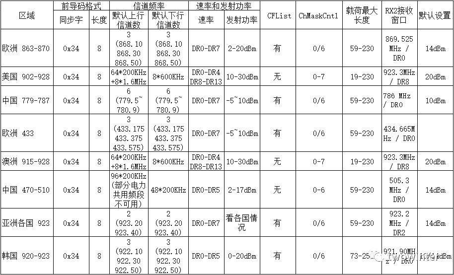
In fact, this table also reveals an interesting point: why South Korea’s parameters are singled out when they are actually quite similar to those of other Asian countries. If you remember the board member records mentioned earlier, you should know the status of SK Telecom in the LoRa Alliance. With such a high status, a little special treatment isn’t too much to ask, right?
7. Examples of LoRaWAN Applications
Now that we have covered the above information, you should have a systematic understanding of LoRaWAN.
After intermittently studying LoRaWAN for the past few months, I deeply feel that IoT manufacturers need to invest significantly to fully understand LoRaWAN, especially when encountering various detailed issues during actual projects. However, there are quicker and easier methods, such as utilizing our long-term partner – Xiamen Sixin’s LoRaWAN serial modules, which provide very simple and clear serial AT commands, allowing manufacturers to focus on their diverse business applications. Yes, that saying goes, what belongs to God is God’s, and what belongs to Caesar is Caesar’s.
i. Basic Network Parameter Configuration
Configure DevEUI
AT+DEI=11:22:33:44:55:66:77:88
Configure AppEUI
AT+AEI=11:22:33:44:55:66:77:88
Configure AppKey
AT+AKY=00:11:22:33:44:55:66:77:88:99:AA:BB:CC:DD:EE:FF
ii. Network Joining Operation
AT+JON // Start joining the network
+JON: 1 Failed // First join failed
+JON: 2 OK
iii. Data Transmission and Reception
Send data 12345 to port 21
AT+TXA=21,12345
Receive data notification from port 21
+RCV:21,abcd
8. End
That’s all.