The backlight module is a very important component in the display industry. Today, let’s take a look at this backlight.
Below is a typical structure; the actual situation is more complex because, with the development of technology, companies use different micro-structural solutions or combinations of functions to reduce costs or avoid patents. However, the main material principles remain unchanged.
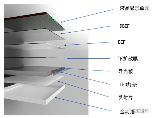
First, let’s look at this simplified diagram. At the top is the liquid crystal display unit, also called cell.The metal frame at the bottom serves a protective function, such as an iron frame, or there are plastic frames, preventing the optical films inside from being affected by impacts and other external forces. Let’s examine the light path one by one.
Light Source
LED light bars. Initially, CCFL tubes were used, but with the advancement of LED technology, increasing brightness and energy efficiency, a design with LEDs on the entire back emerged, known as “direct-lit” light sources. However, this design is no longer in use.
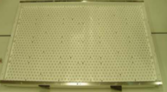
Figure 2: Direct-lit LED light source
As technology develops, with the increase in LED luminous power and the invention of 3M brightness enhancement films, the “edge-lit” light source has emerged, and it is now in its third generation.
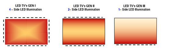
Figure 3: Edge-lit LED light source (the black dashed line represents the LED light bar)
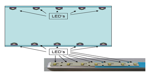
After the LED light source emits light, materials that shade or reflect direct the light into the edge of the light guide plate.
Light Guide Plate
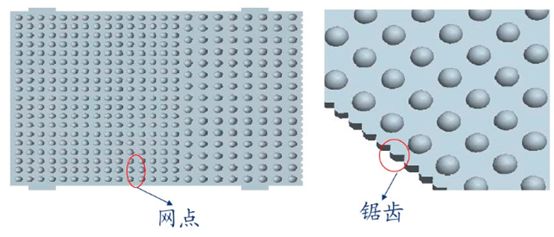
The light from the LED light bar shines into the internal light guide plate from the side edge, and the edges of the light guide plate are serrated as shown below.
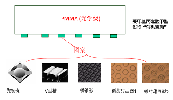
Understanding the working principle of the light guide plate. If it is a pure PC or PMMA transparent plate without surface micro-structures, the light will propagate as shown in the following diagram.
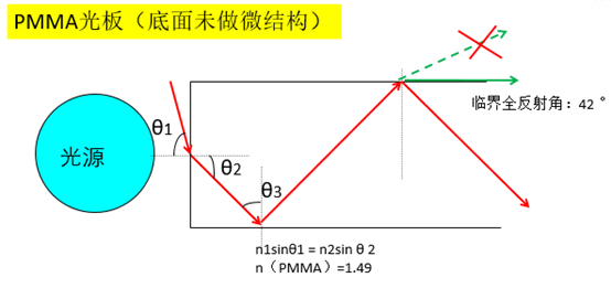
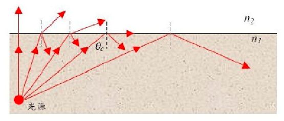
Light travels from one medium to another, reflecting and refracting at the interface. When the angle of incidence exceeds the critical angle θc, total reflection occurs. However, if some graphic processing is done at the bottom of the plate, it can change the angles of incidence and reflection.
Then the light will propagate as shown in the following diagram. Most of it will propagate out from the top of the plate.
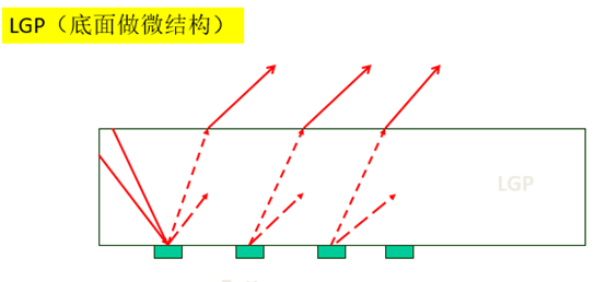
Most of the light will go upwards into the display unit.
Reflective Film
Most of the light coming out of the light guide plate goes upwards, but some also goes down. This part of the light also needs to be fully utilized. Therefore, a reflective film layer is added below to direct the light upwards. A typical reflective film structure is shown below.
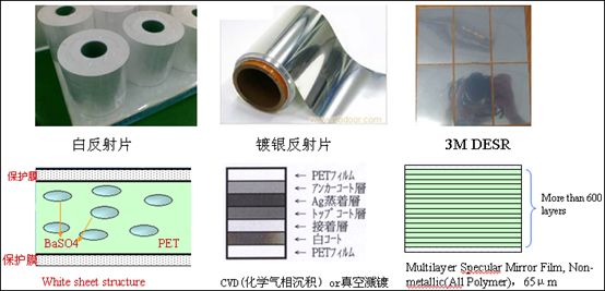
Currently, companies like Jizhi and Changyang in China are producing reflective sheets of the aforementioned types. The best, and also the most expensive, is 3M’s ESR enhanced mirror reflective film, which can achieve a reflectivity of 98%, while other solutions are slightly lower.
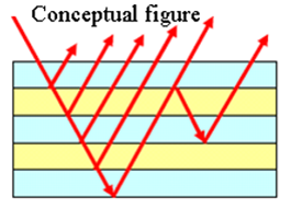
3M’s film has a nano-level thickness coating of 1/4 of the wavelength of light. Utilizing optical principles, it enhances reflection, generally consisting of about 500 layers, totaling 0.065mm thick. In the most extreme cases, 3M has applied this technology to their projectors, achieving over 700 layers.
The most common reflective sheets today are based on PET, printed or laminated with a white reflective layer, with the main raw material being barium sulfate, or silver-coated reflective layers on PET.
Diffusion Film
Once the light exits the light guide plate, including the light reflected from the reflective sheet, it enters the diffusion film.
The structure of the diffusion film is as follows:
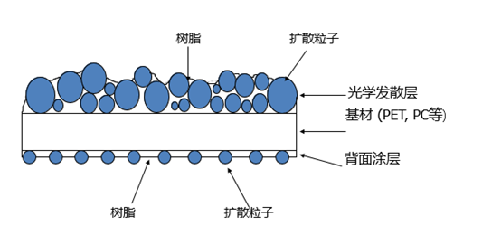
The diffusion film uses the particles above, through the curved surfaces of different particle sizes, to create a large diffusion angle. The coating below has an anti-static function to prevent adhesion to the light guide plate.
In addition, the diffusion film can blur the dots of light on the light guide plate, making the light uniform; eliminate Newton rings and optical interference stripes.
The lower diffusion film is labeled in the image, and you may also see upper diffusion films in other materials, which are designs from about 15 years ago. Nowadays, products have integrated the functions of upper diffusion into other materials to reduce overall thickness, cut costs, and avoid certain patents, such as BEF, DBEF etc.
The function of the upper diffusion basically protects the BEF prism film, increases the light exit angle, and ensures uniform light output. These functions can be integrated into other films.
BEF Brightness Enhancement Film
Once the light exits the diffusion film, it enters the BEF, also known as Prism sheet.
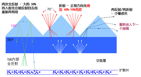
The light entering from the diffusion film encounters three situations: one is reflected back, about 50%; the second is refracted, allowing light to enter DBEF and other optical films; the third involves refraction and reflection, entering other prism structures for further utilization.
Through these light paths of reflection and refraction, the energy of light can be saved by 40%-70%. This reduces the energy demand on LED light sources, saving electricity, being environmentally friendly, and enhancing the battery life of electronic products.
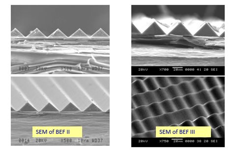
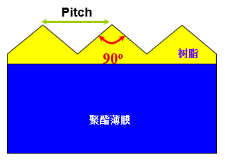
A typical structure of the prism film is shown above. The angle is 90 degrees, which provides the best focusing effect. The larger the pitch, the better the focusing effect.
Although the first image shows a single BEF, many now use 2 BEFs or simply combine 2 BEFs together to gather light from both the vertical and horizontal directions.
BEF concentrates the energy of light, making the light stronger from the front while weakening it from the sides. Although it increases the brightness of the display, it also affects the final light exit angle of the display. This means that if you view the television from the side, the image will not be clear.
DBEF
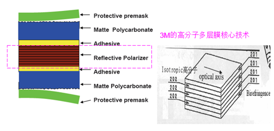
DBEF is Dual Brightness Enhancement Film, which may not be easily understood in English, so we can call it reflective polarizing brightness enhancement film. This is the product with the highest technical content in the backlight.
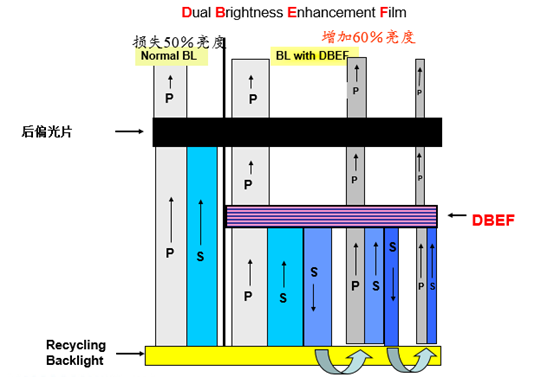
The above describes the working purpose of DBEF, which utilizes multiple layers of materials with different refractive indices. When white light passes through DBEF, it gets polarized into P light parallel to the incident plane and S light perpendicular to it; P comes from the German word for parallel, while S means perpendicular. DBEF can transmit P light while reflecting S light. This allows S light to pass through the diffusion film and become polarized again, turning back into white light, which then re-enters DBEF. This back-and-forth reflection and incidence fully utilize the light’s energy, achieving a brightness enhancement effect.
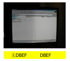
The image below shows the difference in display quality with and without DBEF.
3M’s BEF and DBEF are leading products in this industry, protected by over 100 patents. Of course, with the advancement of technology and the expiration of some BEF patents, many manufacturers of BEF have emerged.
The optical films for backlighting have long been dominated by suppliers from the US and Japan/South Korea. Due to major manufacturers in the optoelectronic industry such as AUO and Innolux, Taiwan also has strong capabilities in optical films. However, the mainland is relatively weak in this area, mostly participating in the cutting or assembly of optical films, with lower technical content. In recent years, companies like Kangdexin, Jizhi, and Changyang have invested in this field, and domestic products are now competing, mainly producing relatively simple reflective sheets, diffusion sheets, and light guide plates, which is already quite good.
Unfortunately for this industry, the technology of OLED is continuously maturing, and since OLED displays are self-emissive and do not require backlight sources, this has a significant impact on the industry.