1. SPI Bus
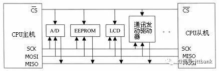
The Serial Peripheral Interface (SPI) bus technology is a synchronous serial interface introduced by Motorola. Most MCUs (Microcontrollers) produced by Motorola, such as the 68 series MCUs, are equipped with SPI hardware interfaces. SPI is used for full-duplex, synchronous serial communication between the CPU and various peripheral devices. It can simultaneously transmit and receive serial data. It requires only four lines to complete communication between the MCU and various peripheral devices, which are: Serial Clock Line (CSK), Master In/Slave Out Data Line (MISO), Master Out/Slave In Data Line (MOSI), and Low Active Slave Select Line (CS). These peripheral devices can be simple TTL shift registers, complex LCD display drivers, A/D, D/A conversion subsystems, or other MCUs. When SPI operates, data in the shift register is output bit by bit from the output pin (MOSI) (with the most significant bit first), while data received from the input pin (MISO) is shifted into the shift register (with the most significant bit first). After sending a byte, the byte data received from another peripheral device enters the shift register. The main SPI clock signal (SCK) synchronizes the transmission. A typical system block diagram is shown below.
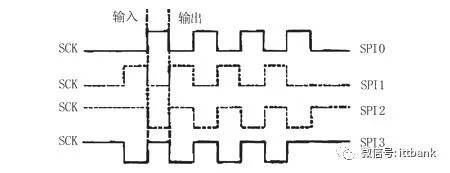
The main features of SPI include: the ability to simultaneously transmit and receive serial data; • Can operate as either a master or a slave; • Provides a programmable clock frequency; • Sends end interrupt flags; • Write collision protection; • Bus contention protection, etc. Figure 2 shows the four modes of operation for the SPI bus, with the most widely used being SPI0 and SPI3 modes (solid lines indicate):
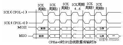
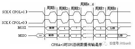
The SPI module can configure the output serial synchronous clock polarity and phase according to the requirements of the peripheral device for data exchange. The clock polarity (CPOL) does not significantly affect the transmission protocol. If CPOL=0, the idle state of the serial synchronous clock is low; If CPOL=1, the idle state of the serial synchronous clock is high. The clock phase (CPHA) can be configured to select one of two different transmission protocols for data transmission. If CPHA=0, data is sampled on the first edge (rising or falling) of the serial synchronous clock; If CPHA=1, data is sampled on the second edge (rising or falling) of the serial synchronous clock. The clock phase and polarity of the SPI master module and the peripheral device it communicates with should be consistent. The timing of the SPI bus interface is shown in the figure below.
2. CAN BusWhat is the CAN Bus? The Controller Area Network (CAN) is one of the most widely used field buses internationally, first proposed by Bosch in Germany. CAN is a multi-master serial communication bus with basic design specifications requiring high bit rates, high electromagnetic interference resistance, and the ability to detect any errors on the bus. When the signal transmission distance reaches 10Km, CAN can still provide data transmission rates of up to 50Kbit/s.
CAN has several superior characteristics:A. Lower cost with extremely high bus utilization; B. Data transmission distances can reach up to 10Km, with transmission rates up to 1Mbit/s; C. Reliable error handling and detection mechanisms, with the ability to automatically retransmit corrupted messages; D. Nodes can automatically exit the bus in case of severe errors; E. Messages do not contain source or destination addresses, only identifiers to indicate functional and priority information; Due to human, natural, and other external influences, as well as the pursuit of safety, reliability, authenticity, and real-time performance in public transport systems, we have higher requirements for communication methods and devices, making CAN bus networks our best choice.CAN Bus Field buses are one of the hot topics in today’s automation technology development, often referred to as the computer local area network in the field of automation. Its emergence provides strong technical support for real-time and reliable data communication between nodes in distributed control systems. CAN (Controller Area Network) falls under the category of field buses and is an effective serial communication network that supports distributed control or real-time control. Compared to many RS-485 based distributed control systems, distributed control systems based on the CAN bus have significant advantages in the following aspects: First, the CAN controller operates in a multi-master mode, where all nodes in the network can compete to send data to the bus using a lossless structure with bitwise arbitration based on bus access priority (determined by message identifiers), and the CAN protocol eliminates station address encoding, replacing it with encoding of communication data, allowing different nodes to receive the same data simultaneously. These features make the data communication between nodes in a CAN bus network highly real-time and facilitate redundancy structures, improving system reliability and flexibility. In contrast, RS-485 can only form a master-slave structure, and communication can only be conducted in a master polling manner, resulting in poorer real-time performance and reliability. Secondly, the CAN bus connects to the physical bus through the two output terminals CANH and CANL of the CAN controller interface chip 82C250, where the state of the CANH terminal can only be high or floating, and the CANL terminal can only be low or floating. This ensures that there is no short circuit on the bus when multiple nodes attempt to send data simultaneously, which could damage certain nodes, as can happen in RS-485 networks. Moreover, CAN nodes have an automatic output shutdown function in case of severe errors, ensuring that the operations of other nodes on the bus are not affected, preventing situations where individual node issues cause the bus to enter a “deadlock” state. Additionally, the complete communication protocol of CAN can be implemented by the CAN controller chip and its interface chip, significantly reducing system development difficulty and shortening the development cycle, which is unmatched by RS-485 that only has electrical protocols. Furthermore, compared to other field buses, the CAN bus is characterized by high communication rates, ease of implementation, and high cost-performance ratio, which are important reasons for its strong market competitiveness in various fields. CAN (Controller Area Network) is a type of industrial field bus. Compared to general communication buses, CAN bus data communication has outstanding reliability, real-time performance, and flexibility. Due to its excellent performance and unique design, the CAN bus is receiving increasing attention. Its application in the automotive field is the most widespread, with some well-known automotive manufacturers worldwide, such as BENZ, BMW, PORSCHE, ROLLS-ROYCE, and JAGUAR, using the CAN bus for data communication between internal control systems and various detection and execution mechanisms. Additionally, due to the characteristics of the CAN bus, its application range is no longer limited to the automotive industry but has expanded to automatic control, aerospace, navigation, process industries, machinery, textile machinery, agricultural machinery, robotics, CNC machine tools, medical devices, and sensors. CAN has formed an international standard and is recognized as one of the most promising field buses. Typical application protocols include: SAE J1939/ISO11783, CANOpen, CANaerospace, DeviceNet, NMEA 2000, etc.1. What is the CAN Bus? CAN stands for Controller Area Network. It is one of the popular field buses internationally. It is particularly suitable for building interconnected device network systems or subsystems.2. Characteristics of the CAN Bus? CAN is one of the few field buses with international standards. The maximum communication distance for CAN is 10 kilometers (at a rate of 5Kbps), or a maximum communication rate of 1Mbps (at a communication distance of 40 meters). The number of nodes on the CAN bus can reach up to 110. Communication media can be selected from twisted pair, coaxial cable, or fiber optics. CAN uses non-destructive bus arbitration technology, where lower priority nodes actively withdraw from sending when multiple nodes attempt to send data simultaneously, allowing higher priority nodes to continue sending, thus saving bus arbitration time. CAN operates in a multi-master mode, where any node on the network can actively send information to other nodes at any time. CAN uses message identifiers to recognize nodes on the network, categorizing them into different priority levels, with higher priority nodes enjoying the privilege of sending messages first. Messages have a short frame structure, and the short transmission time reduces the probability of interference. CAN has a good verification mechanism, ensuring the reliability of CAN communication.3. Application Fields of the CAN Bus The CAN bus was originally designed by Bosch in Germany for monitoring and control in the automotive industry. It is now applied in railways, transportation, defense, engineering, industrial machinery, textiles, agricultural machinery, CNC, medical devices, robotics, buildings, and security systems.3. I2C (Inter-Integrated Circuit) Bus The I2C (Inter-Integrated Circuit) bus is a two-wire serial bus developed by PHILIPS for connecting microcontrollers and their peripheral devices. The I2C bus originated in the 1980s, initially developed for audio and video devices, and is now primarily used in server management, including communication of individual component statuses. For example, administrators can query each component to manage system configurations or monitor component functional statuses, such as power supplies and system fans. It allows for real-time monitoring of multiple parameters such as memory, hard drives, networks, and system temperatures, enhancing system security and facilitating management.1. Characteristics of the I2C Bus The main advantages of the I2C bus are its simplicity and effectiveness. Since the interface is directly on the component, the I2C bus occupies very little space, reducing the space on the circuit board and the number of chip pins, thus lowering interconnection costs. The bus length can reach up to 25 feet and can support up to 40 components at a maximum transmission rate of 10Kbps. Another advantage of the I2C bus is that it supports multi-mastering, where any device capable of sending and receiving can become the master bus. A master can control the transmission of signals and clock frequencies. However, only one master can exist at any given time.2. Working Principle of the I2C Bus 2.1. Composition of the Bus and Signal Types The I2C bus consists of a data line (SDA) and a clock line (SCL) for serial communication, capable of sending and receiving data. Data is transmitted bidirectionally between the CPU and the controlled IC, as well as between ICs, with a maximum transmission rate of 100kbps. Various controlled circuits are connected in parallel on this bus, but like a telephone, each must dial its own number to work, so each circuit and module has a unique address. During the transmission of information, each module circuit connected to the I2C bus can act as both a master (or controlled device) and a transmitter (or receiver), depending on the function it needs to perform. The control signals sent by the CPU are divided into address codes and control quantities, where the address code is used for addressing, i.e., to connect to the circuit that needs to be controlled, determining the type of control; the control quantity determines the category to be adjusted (such as contrast, brightness, etc.) and the amount to be adjusted. Thus, although all control circuits are on the same bus, they are independent and unrelated. There are three types of signals during data transmission on the I2C bus: Start signal, Stop signal, and Acknowledge signal. Start signal: When SCL is high, SDA transitions from high to low, indicating the start of data transmission. Stop signal: When SCL is low, SDA transitions from low to high, indicating the end of data transmission. Acknowledge signal: The receiving IC sends a specific low pulse to the transmitting IC after receiving 8 bits of data, indicating that the data has been received. After the CPU sends a signal to the controlled unit, it waits for the controlled unit to send an acknowledgment signal. The CPU receives the acknowledgment signal and decides whether to continue transmitting signals based on the actual situation. If no acknowledgment signal is received, it is judged that the controlled unit has failed. Currently, many semiconductor integrated circuits have integrated I2C interfaces. Microcontrollers with I2C interfaces include: CYGNAL’s C8051F0XX series, PHILIPS P87LPC7XX series, MICROCHIP’s PIC16C6XX series, etc. Many peripheral devices such as memory, monitoring chips, etc., also provide I2C interfaces.3. Basic Operations of the Bus The I2C protocol uses master/slave bidirectional communication. When a device sends data to the bus, it is defined as a transmitter, and when a device receives data, it is defined as a receiver. Both master and slave devices can operate in receiving and sending states. The bus must be controlled by a master device (usually a microcontroller), which generates the serial clock (SCL) to control the direction of transmission on the bus and generates start and stop conditions. The data state on the SDA line can only change while SCL is low; during the high state of SCL, changes in SDA state are used to indicate start and stop conditions. 3.1. Control Byte After the start condition, a control byte for the device must follow, where the high four bits are the device type identifier (different chip types have different definitions, EEPROM is generally 1010), followed by three bits for chip selection, and the last bit is the read/write bit, where 1 indicates a read operation and 0 indicates a write operation. 3.2. Write Operation Write operations are divided into byte write and page write, with variations based on the number of bytes loaded by the chip at one time. 3.3. Read Operation Read operations have three basic types: current address read, random read, and sequential read. Figure 4 shows the timing diagram for sequential read. It should be noted that: The 9th clock cycle of the last read operation is not “don’t care.” To end the read operation, the master must issue a stop condition during the 9th cycle or keep SDA high during the 9th clock cycle and then issue a stop condition.In the application of the I2C bus, the following points should be noted: 1) Strictly follow the timing diagram requirements for operations, 2) If connecting to a microcontroller with internal pull-up resistors on the port line, external pull-up resistors may not be needed. 3) In the program, to match the corresponding transmission rate, a NOP instruction can be used after the port line operation instructions to add a certain delay. 4) To reduce unexpected interference signals when rewriting data in EEPROM, external write protection pins (if available) can be used, or a flag word can be written into unused space in the EEPROM, and a check can be performed at each power-up or reset to determine if the EEPROM has been accidentally rewritten.Additional: I2C Bus In modern electronic systems, there are numerous ICs that need to communicate with each other and with the outside world. To provide hardware efficiency and simplify circuit design, PHILIPS developed a simple bidirectional two-wire serial bus for internal IC control called I2C (Inter-IC Bus). The I2C bus supports any IC manufacturing process, and PHILIPS and other manufacturers provide a wide variety of I2C-compatible chips. As a patented control bus, I2C has become a global industrial standard. Each I2C device has a unique address and can be a single-receiving device (e.g., LCD driver) or a device that can both receive and send (e.g., memory). Transmitters or receivers can operate in master mode or slave mode, depending on whether the chip must initiate data transmission or is merely being addressed. I2C is a multi-master bus, meaning it can be controlled by multiple connected devices. In the early days, the maximum data transmission rate of the I2C bus was 100Kbits/s, using 7-bit addressing. However, due to the rapid increase in data transmission rates and application functions, the I2C bus has also been enhanced to fast mode (400Kbits/s) and 10-bit addressing to meet the demands for higher speeds and larger addressing space. The I2C bus has always kept pace with advanced technology while maintaining backward compatibility. Recently, a high-speed mode has been added, with speeds up to 3.4Mbits/s. This allows the I2C bus to support existing and future high-speed serial transmission applications, such as EEPROM and Flash memory.4. I2S BusI2S has three main signals: 1. Serial Clock SCLK, also called Bit Clock (BCLK), corresponds to each bit of digital audio data, with one pulse for each SCLK. The frequency of SCLK = 2 × Sampling Frequency × Number of Sampling Bits 2. Frame Clock LRCK, used to switch between left and right channel data. LRCK being “1” indicates that left channel data is being transmitted, while “0” indicates that right channel data is being transmitted. The frequency of LRCK equals the sampling frequency. 3. Serial Data SDATA, which is the audio data represented in binary two’s complement. I2S (Inter-IC Sound Bus) is a bus standard established by Philips for audio data transmission between digital audio devices. In Philips’ I2S standard, both hardware interface specifications and digital audio data formats are defined.I2S has three main signals: 1. Serial Clock SCLK, also called Bit Clock (BCLK), corresponds to each bit of digital audio data, with one pulse for each SCLK. The frequency of SCLK = 2 × Sampling Frequency × Number of Sampling Bits 2. Frame Clock LRCK, used to switch between left and right channel data. LRCK being “1” indicates that left channel data is being transmitted, while “0” indicates that right channel data is being transmitted. The frequency of LRCK equals the sampling frequency. 3. Serial Data SDATA, which is the audio data represented in binary two’s complement. Sometimes, to better synchronize between systems, an additional signal MCLK, called the Master Clock or System Clock, is also transmitted, which is 256 or 384 times the sampling frequency. A typical I2S signal is shown in Figure 3. (Figure 3 I2S Signal) Figure 3
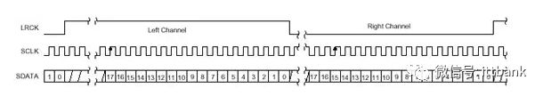
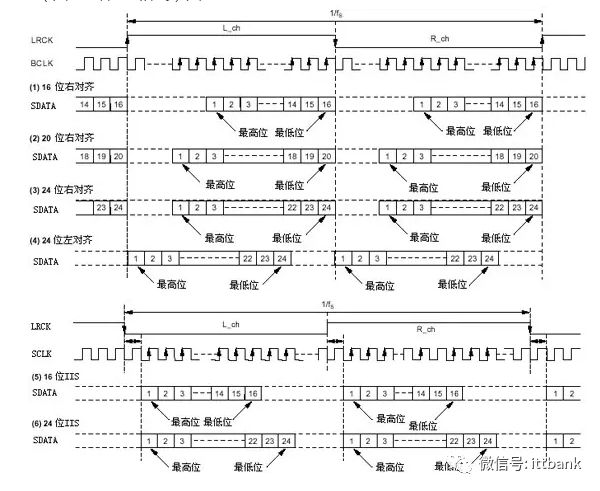
In I2S format signals, regardless of how many bits of valid data there are, the most significant bit always appears at the second SCLK pulse after the LRCK change (i.e., the start of a frame). This allows the effective bit count at the receiving end to differ from that at the sending end. If the receiving end can handle fewer effective bits than the sending end, it can discard the extra low bits in the data frame; if the receiving end can handle more effective bits than the sending end, it can fill in the remaining bits itself. This synchronization mechanism makes interconnection between digital audio devices more convenient and prevents data misalignment. With technological advancements, various data formats have emerged under the unified I2S interface. Depending on the position of the SDATA data relative to LRCK and SCLK, they can be classified into left-aligned (less commonly used), I2S format (the format specified by Philips), and right-aligned (also known as Japanese format or standard format). These different formats are shown in Figures 4 and 5. (Figure 4 Various Non-I2S Formats) Figure 4 (Figure 5 Various I2S Formats) Figure 5
To ensure the correct transmission of digital audio signals, the sending and receiving ends should adopt the same data format and length. Of course, for I2S format, the data length can differ.5. SSP Bus The SSP bus is compatible with SPI, SSI, and Microwire bus interfaces.
Recommended to follow 👇 the public account to learn more about electronic technology knowledge!

-
Hardcore Science: How many chips can be produced from a wafer?
-
The bizarre circuit built by hardware engineers, the signal waveform is actually a bat.
-
FreeRTOS and its applications, a lengthy article for beginners.
-
A divine explanation of the four major communication interfaces: UART/I2C/SPI/1-wire.
-
This constant current circuit design scheme, you may not have used before.
-
The top 10 microcontrollers favored by American engineers in 2021.
-
What are the differences between transistors and MOSFETs? Should I use MOSFETs or transistors?