Installation methods for strain monitoring sensors on natural gas pipelines
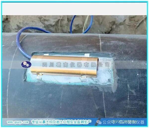
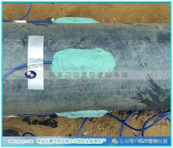
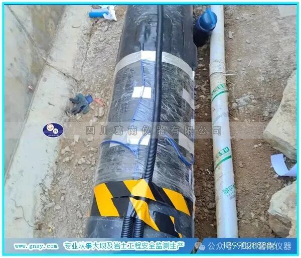
The installation of strain monitoring sensors on natural gas pipelines is a critical step to ensure the safe operation of the pipeline. It is essential to follow the specifications strictly to guarantee the accuracy and reliability of the monitoring data. First, the surface of the pipeline must be thoroughly cleaned before installation to remove impurities such as oil, rust, and dust. Sandpaper or specialized cleaning agents can be used to polish the surface, ensuring that the sensor is in close contact with the pipeline surface. For sensors that need to be fixed by welding, a low heat input welding process should be used to avoid altering the material properties of the pipeline or causing additional stress concentration due to high temperatures. After welding, non-destructive testing should be conducted to confirm the quality of the weld.
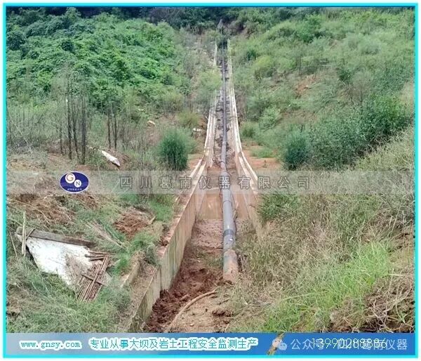
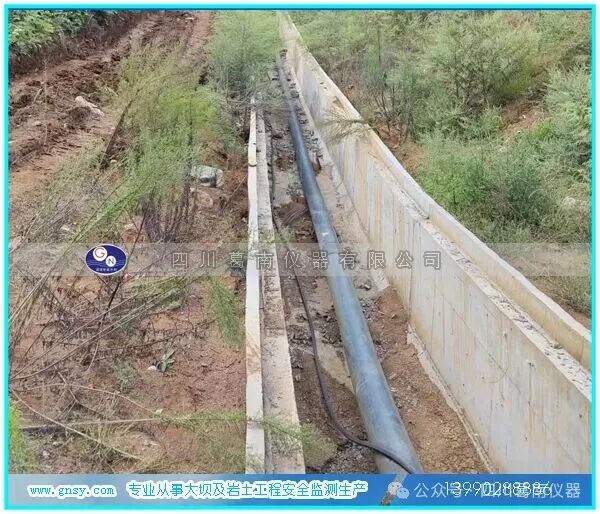
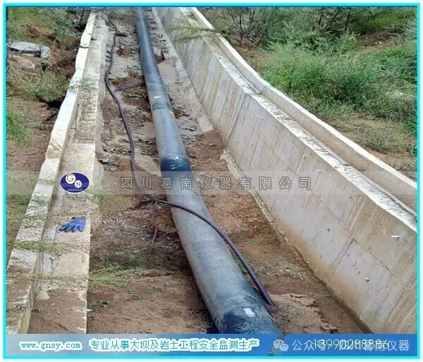
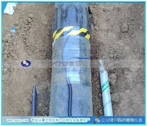
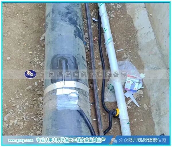
Secondly, the choice of installation location for the sensor is crucial. It should typically be installed in areas of stress concentration on the pipeline, such as elbows, tees, near valves, and areas that have historically experienced corrosion or damage. During installation, specialized clamps or brackets should be used to secure the sensor to the outer wall of the pipeline, ensuring that the sensor’s axis is parallel or perpendicular to the pipeline axis (depending on monitoring requirements) to avoid measurement errors due to installation angle deviations. For adhesive-type sensors, a specialized adhesive should be evenly applied, and the sensor should be gently pressed to ensure full contact with the pipeline surface. Subsequent operations should only be performed after the adhesive has fully cured.
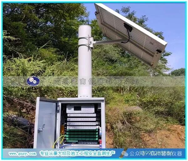
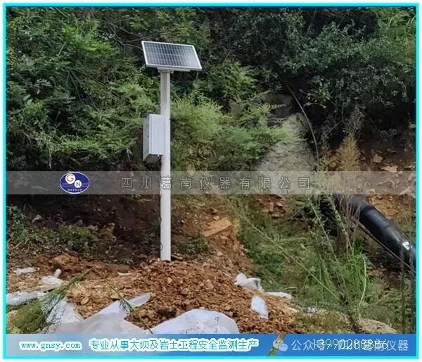
During the installation process, care must be taken to avoid mechanical shocks or vibrations affecting the sensor, especially when installing while the pipeline is in operation. Temporary support measures should be taken to prevent damage to the sensor due to pipeline displacement. After installation, initial debugging of the sensor should be performed to check the integrity of the connection lines, ensure normal signal transmission, and record initial readings as baseline data. Additionally, regular inspections of the installation location should be conducted to ensure that the sensor is securely fixed, the protective cover is intact, and that it is not affected by external environmental factors (such as rain, direct sunlight, or chemical corrosion) to extend the sensor’s lifespan and monitoring accuracy.
Installation and Welding Precautions for Vibrating Wire Point-Weld Strain Gauges
Instrument Composition:
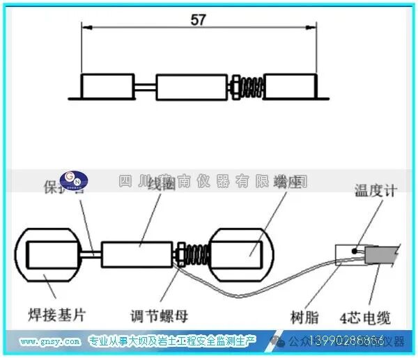
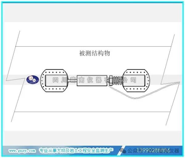
The vibrating wire point-weld strain gauge consists of a welded substrate, coil, protective tube, adjustment nut, end seat, thermometer, cable, and other components.
Working Principle:
Strain measurement uses the vibrating wire principle: a steel wire is tensioned between two mounting blocks, which are welded to the surface of the steel component to be measured.
Deformation of the surface (such as strain changes) causes relative movement between the two end seats, resulting in a change in the tension of the steel wire. An electromagnetic coil, positioned close to the steel wire, excites the wire and measures its resonance frequency.
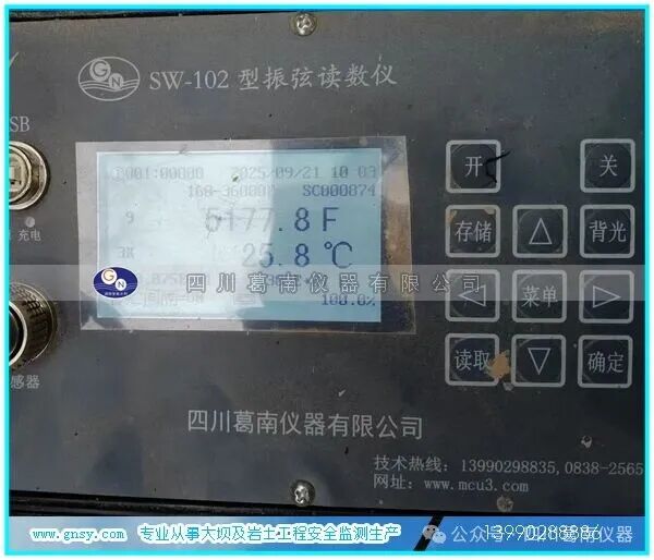
After connecting the vibrating wire readout instrument to the strain gauge, the readout instrument can provide the necessary voltage pulses to excite the wire and directly display the microstrain period or other quantities. This allows for the measurement of the strain value of the structure. Simultaneously, the temperature value at the embedded point can be measured.
The point-weld strain gauge is fully sealed and in a tensioned state. By connecting the excitation coil’s wires to the readout instrument, the initial reading of the strain gauge can be obtained. The observed reading should be between 4000-4500F modulus. Gently pressing the two ends of the strain gauge should decrease the reading, while pulling the ends should increase the displayed reading. Excessive pressure (or tension) on one end of the strain gauge (>4.5kg) should be avoided, as it may damage the steel wire.
Check the electrical resistance between the two wires of the vibrating wire strain gauge (usually red and black wires); the coil resistance should be approximately 120Ω±10Ω. When testing, the cable resistance should also be added (22AWG stranded copper wire resistance is approximately 50Ω/KM, multiplied by 2 for the two-way). The resistance of the thermistor thermometer (temperature sensing element) should also be checked (usually white and green wires).
Before installing the strain gauge, the pre-tension or pre-compression state of the strain gauge should be adjusted according to the structural monitoring purpose. The tension of the strain gauge provided by our company is set to the middle range at the factory, with a strain range of approximately ±1500 microstrain. Even if the strain gauge is set to the middle range for installation, all strain gauges should be checked for normal operation before installation.
If the direction of strain change is known, the tension of the steel wire can be adjusted to a greater range for compression or tension state. First, read a strain gauge reading, then adjust the adjustment screw on the strain gauge to achieve the pre-tension or pre-compression state.
Sichuan Genan Instrument Co., Ltd. Genan Xiaodu 13990288886 www.gnsy.com