The download and installation methods for PLC programming software from various brands are similar. Below, we will explain the download and installation methods for the Siemens S7-200 SMART series PLC programming software as an example.1.0 Downloading Siemens PLC Programming SoftwareThe Siemens S7-200 SMART series PLC uses the STEP 7 Micro/WIN SMART programming software, which is free software available for download from the Siemens official website (registration on the website is required before downloading), as shown in Figure 3-2.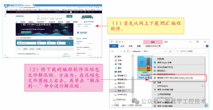
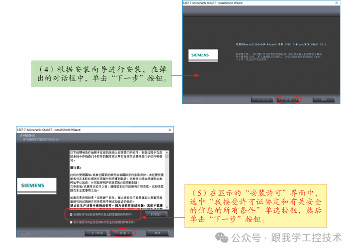
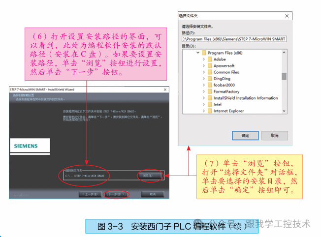
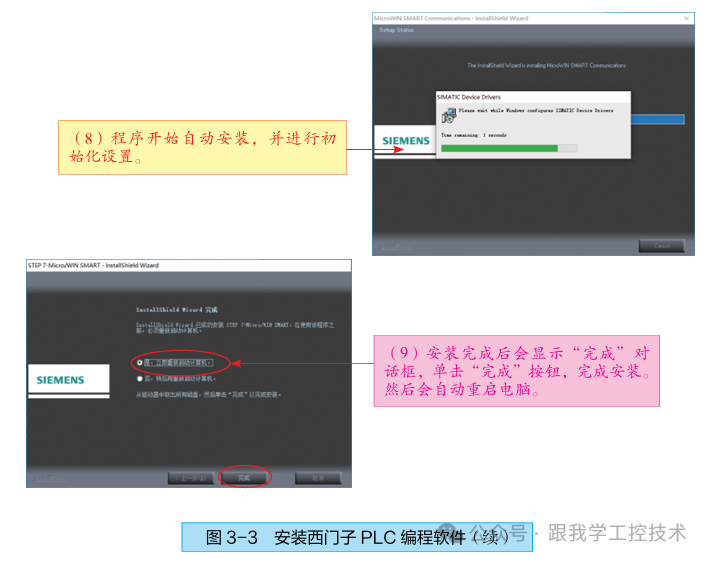
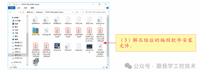 Figure 3-2 Downloading PLC Programming Software1.1 Installation Method for Siemens PLC Programming SoftwareNext, we will explain the installation method for the Siemens PLC programming software using the STEP 7 Micro/WIN SMART programming software as an example, as shown in Figure 3-3.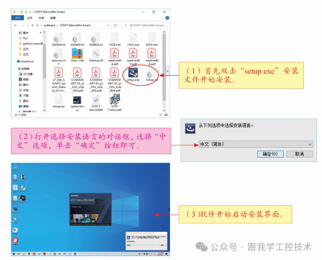
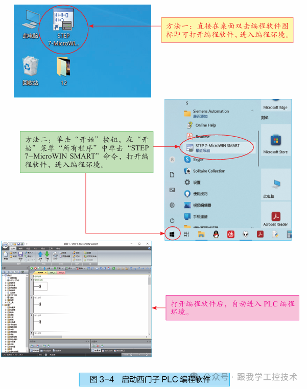
 Using Siemens PLC Programming SoftwareNext, we will explain the operation method of the Siemens PLC programming software using the STEP 7-Micro/WIN SMART programming software as an example.2.1 Starting the Siemens PLC Programming SoftwareAfter the software installation is complete, start the programming software to enter the programming environment, as shown in Figure 3-4.
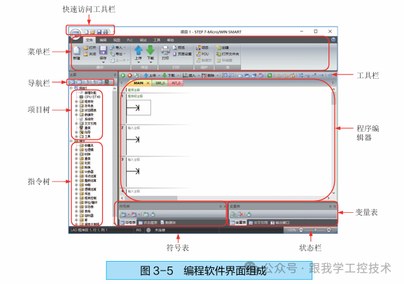
 2.2 Siemens STEP 7-MicroWIN SMART Programming Software Interface Before using the STEP 7-MicroWIN SMART programming software, you should familiarize yourself with the functions of each module in the programming software interface. Figure 3-5 shows the programming software interface.
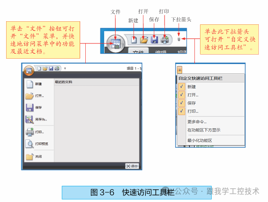
 1. Quick Access ToolbarThe Quick Access Toolbar is located at the top left corner of the programming software window, used for quick access to commonly used menu commands. The Quick Access Toolbar includes buttons such as “File”, “New”, “Open”, “Save”, “Print”, etc., as shown in Figure 3-6.
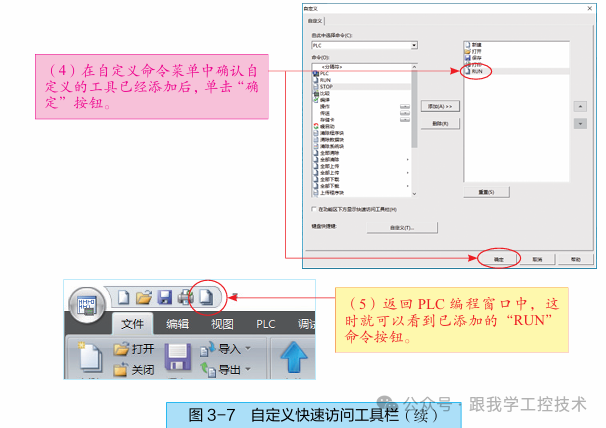
 [Example 3-1] How to Customize the Quick Access Toolbar in Siemens PLCWhen programming with the STEP 7-MicroWIN SMART software, it is sometimes necessary to customize the Quick Access Toolbar to add some commonly used command buttons for quick operation. Below is a case explaining how to add the “RUN” command button to the Quick Access Toolbar, as shown in Figure 3-7.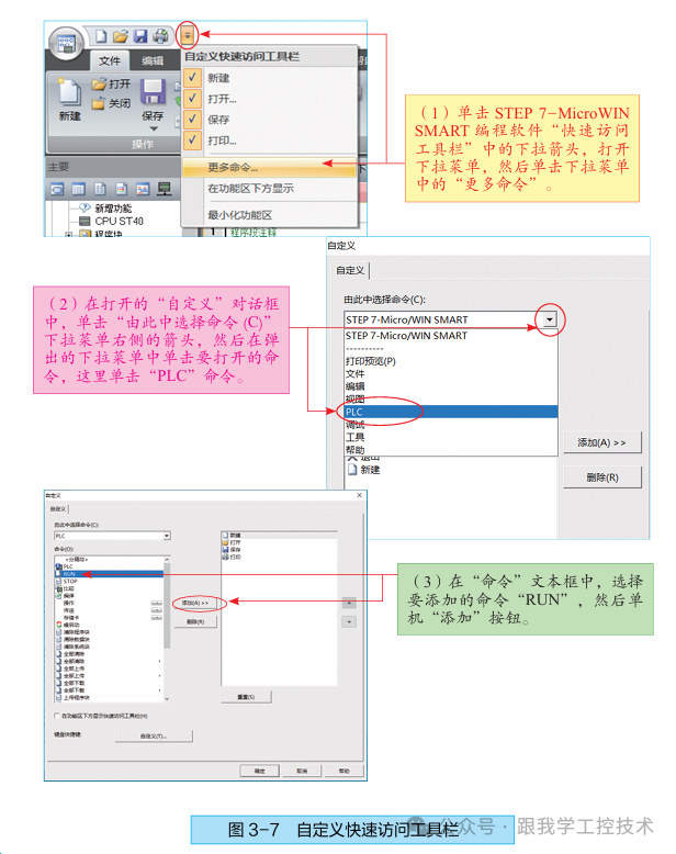
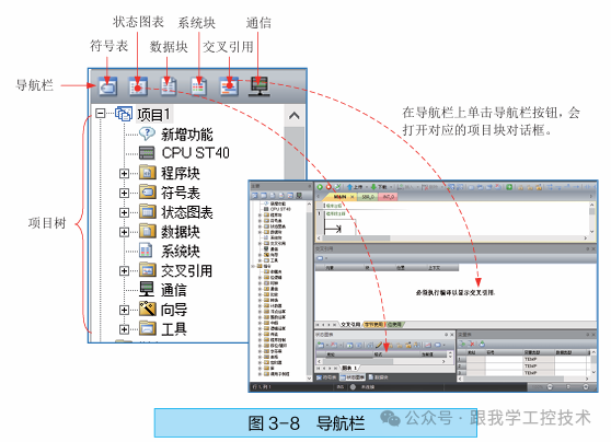
 2. Navigation Bar The navigation bar is used for quick access to project components, displayed above the project tree, allowing quick access to objects in the project tree. Clicking a navigation bar button provides quick access to the corresponding project, as shown in Figure 3-8.
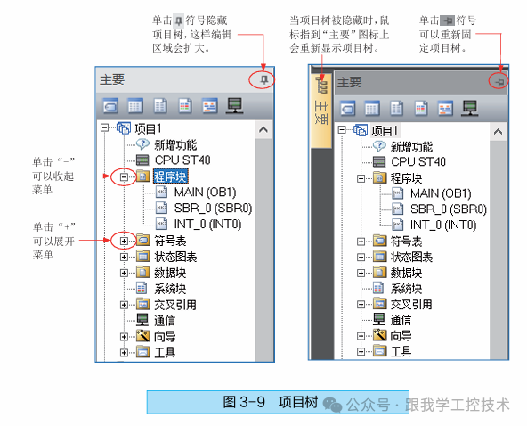
 3. Project Tree The project tree is a very important tool used when editing a project, allowing editing and organization of all elements of the entire project. Figure 3-9 shows the project tree.
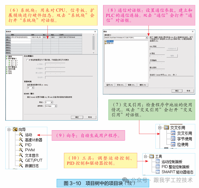
 The project tree mainly includes user-created projects, program blocks, symbol tables, state diagrams, data blocks, system blocks, cross-references, communication, wizards, tools, and other project blocks, as shown in Figure 3-10.
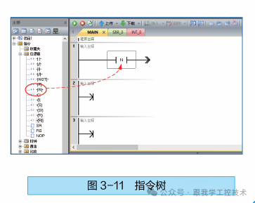
 4. Instruction Tree The instruction tree is used to conveniently and quickly create programs. The instruction tree provides all project objects and all instructions for the current program editor (LAD, FBD, or STL). By dragging and dropping or double-clicking a single instruction, the selected instruction can be automatically inserted at the cursor position in the program editor window, as shown in Figure 3-11.
 5. Menu Bar The menu bar is located at the top of the software window, designed as a ribbon-style menu, displaying all menu options at a glance, with intuitive icons for easier and quicker operation. The menu bar includes seven menu items: File, Edit, PLC, Debug, Tools, View, and Help. Users can customize the “Tools” menu to add their own tools, as shown in Figure 3-12.
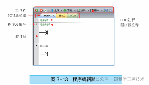
 6. Program EditorThe program editor is the area for writing and editing programs. The program editor window contains the local variable table and program view for the project. The program editor window includes toolbars, POU selectors, POU comments, program segment comments, program segment numbers, and binding lines, as shown in Figure 3-13.
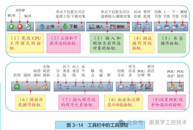
 (1) Toolbar: The toolbar mainly includes commonly used operation buttons and general program elements that can be placed in program segments. Hovering the mouse over a tool button will display the name of the tool button. The tools in the toolbar are shown in Figure 3-14.
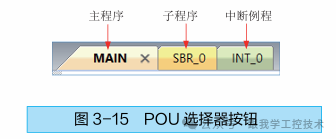
 (2) POU Selector: The POU selector allows switching between the main program, subprogram, or interrupt routine. Clicking the “SBR_0” button directly switches to the subprogram. Figure 3-15 shows the POU selector button.
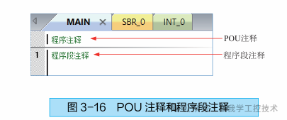
 (3) POU Comments and Program Segment Comments: POU comments are displayed above the first program segment in the POU, providing detailed multi-line POU comment functionality. POU comments can be in English or Chinese, mainly explaining the function of the entire POU, etc.Program segment comments are displayed next to the program segment, providing detailed multi-line comment functionality for each program. Program segment comments can also be in English or Chinese, as shown in Figure 3-16.
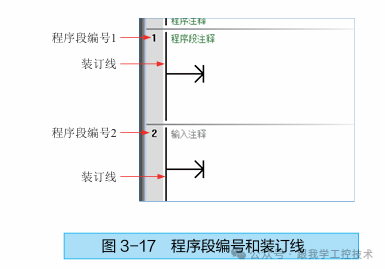
 (4) Program Segment Number: The program segment number is a numeric identifier for each program segment, which is automatically numbered, as shown in Figure 3-17.(5) Binding Line: The binding line is located in the gray area on the left side of the program editor window (see Figure 3-17). Clicking in this area allows selecting a single program segment, or selecting multiple program segments by clicking and dragging. The STEP 7-MicroWIN SMART software will also display various symbols here, such as bookmarks, POU password protection locks, etc.
 7. Symbol Table The symbol table is a list of the correspondence between symbols and addresses, specifying symbol names for memory addresses or constants. The “Symbol Table” dialog allows users to allocate and edit global symbols, which can be used in any POU, not just the POU where the symbol is created, as shown in Figure 3-18.
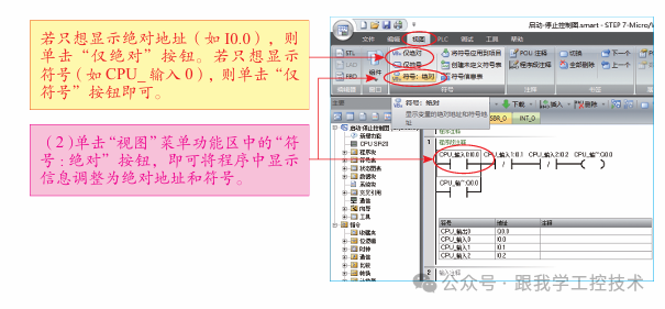
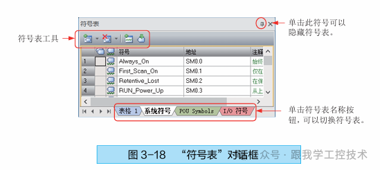 There are three ways to open the “Symbol Table” dialog:(1) Click the “Symbol Table” button in the navigation bar.(2) In the “Project Tree”, click the “+” before “Symbol Table”, then double-click a table name, such as double-clicking “System Symbols”.(3) Click the “View” option menu, then click the drop-down arrow under “Components”, and then click “Symbol Table”.[Example 3-2] How to Change the Displayed Symbols and Addresses of Components in a ProgramThe user wants to display the symbol information table in a ladder diagram program and adjust the displayed information of components in the program to absolute addresses and symbols. The specific operation method is shown in Figure 3-19.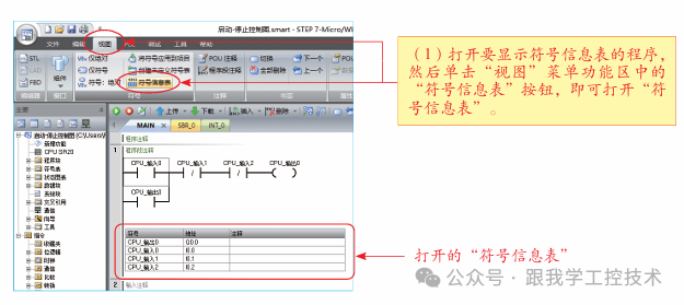
 8. Variable TableDuring the debugging process of the program, if the user wants to monitor a specific set of data, they need to use the variable table. Users can create tables to observe any variable in the entire project. One of the important functions of the variable table is to monitor the list of variables, as shown in Figure 3-20.
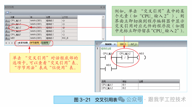
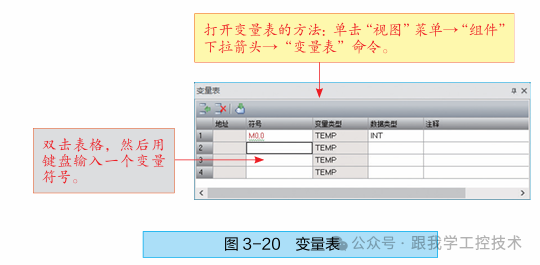 In addition to monitoring functions, the variable table can also modify variable values and force I/O points.9. Cross Reference The cross-reference table is very useful for finding the usage of data addresses in the program. In the cross-reference table, you can view the current assignment status of parameters in the program and check for duplicate assignments, as shown in Figure 3-21.Note: Users must compile the program before viewing the cross-reference table (click the “Compile” button under the “PLC” menu to compile).
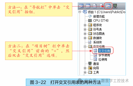
 The method to open the cross-reference table is shown in Figure 3-22.
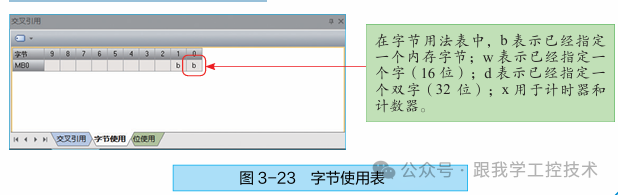
 The byte usage table allows you to view the bytes used in the program and in which memory areas they are used. Additionally, it can check for duplicate assignment errors, as shown in Figure 3-23.
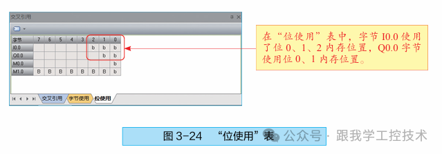
 The bit usage table allows you to view the bits already used in the program and in which memory they are used. Additionally, it can identify duplicate assignment errors. In a correctly assigned program, there should be no bit values in the middle of bytes, as shown in Figure 3-24.
 10. Data Block The data block is used to assign initial values to the V storage area (also known as the variable storage area); data values can be assigned to bytes, words, or double words. Figure 3-25 shows the “Data Block” dialog.
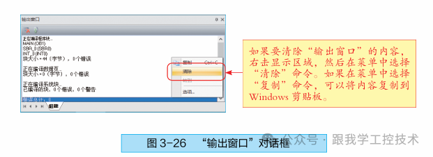
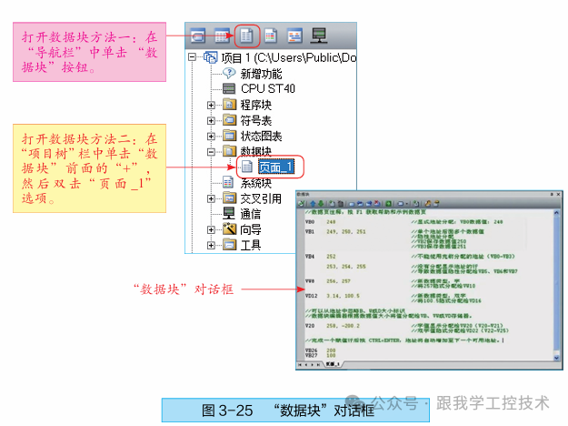 The general rules for assigning addresses and data values in data blocks are as follows. A typical line in a data block includes a starting address, one or more data values, and optional comments after double slashes. The first line of the data block must assign an explicit address, while subsequent lines can assign either explicit or implicit addresses. When entering multiple data after a single address or entering a line that only contains data, the compiler will automatically perform implicit address allocation, determining the appropriate number of V storage areas based on the previous address or the specified length, such as byte, word, or double word.11. Output WindowThe “Output Window” is used to display the results of program compilation (such as whether there are errors, error codes, and locations, etc.). It lists the most recently compiled POU and all errors that occurred during compilation, as shown in Figure 3-26. In the “Output Window”, double-clicking on an error message will automatically scroll the program to the segment where the error is located. After correcting the program errors, recompiling the program will update the compilation results in the “Output Window” and remove the error references for the corrected program segments.
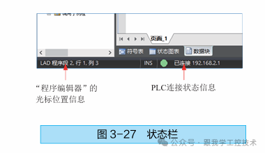
 12. Status Bar The status bar is located at the bottom of the main window, used to display the cursor position information of the “Program Editor” and the PLC connection status information, as shown in Figure 3-27.
 Add me on WeChat to receive 64 Siemens e-books