Based on the “PLC digital input circuit”, continue to improve the input circuit.
Specific requirements:
1. The S8-S13 devices are limit switches located outside the control cabinet, so selection is not performed at this time;
2. The diagram includes devices inside and outside the control cabinet, and it is required to label the connection terminals on the drawing, paying attention to the direction of the terminals.
Generally, the upper end of the terminal connects to the devices inside the control cabinet, while the lower end connects to the devices outside the control cabinet.
Now let’s proceed with the actual operation:
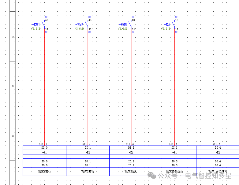
1. In the device navigator, select “Logistics Transmission System” – Control Cabinet – KM1 – select 43||44 (normally open contacts) – right-click – place. Similarly, insert KM3 normally open contacts, KM5 normally open contacts, and KA’s 13||14 (normally open contacts).
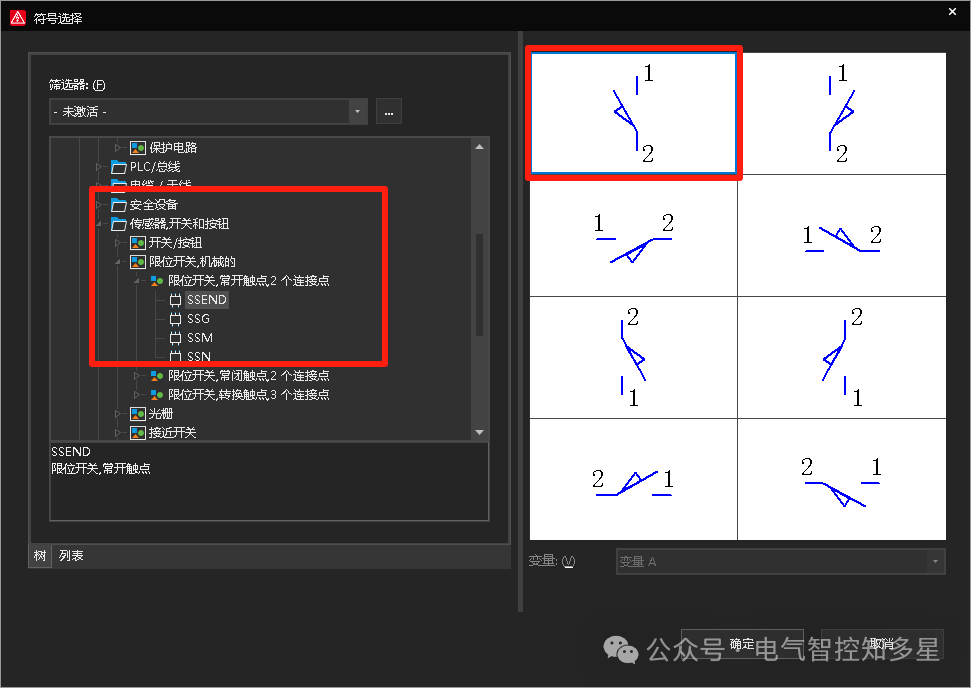
2. Insert symbol – symbol selection – electrical engineering – sensor switches and buttons – limit switch mechanical – select the first icon SSEND for the two connection points of the normally open contact of the limit switch.
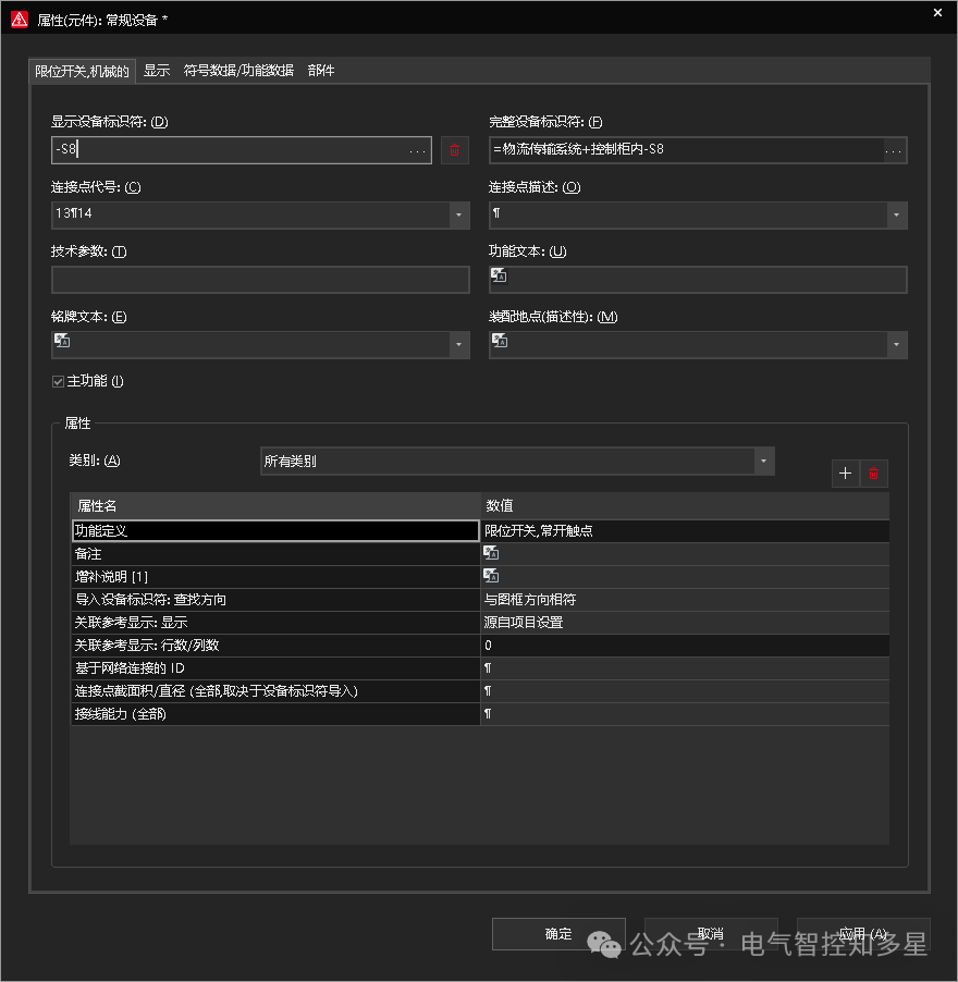
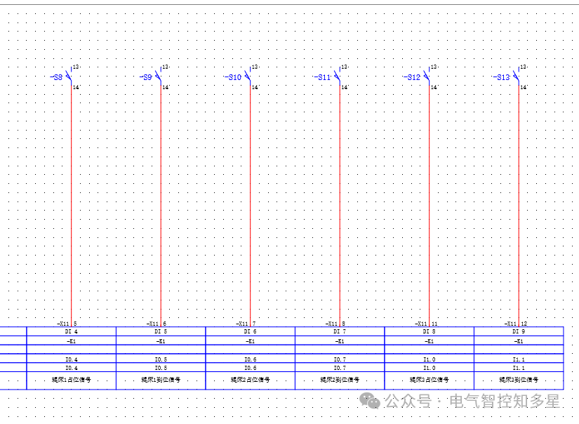
Change the display device identifier to -S8, and similarly insert the western limit switches -S9, -S10, -S11, -S12, -S13.
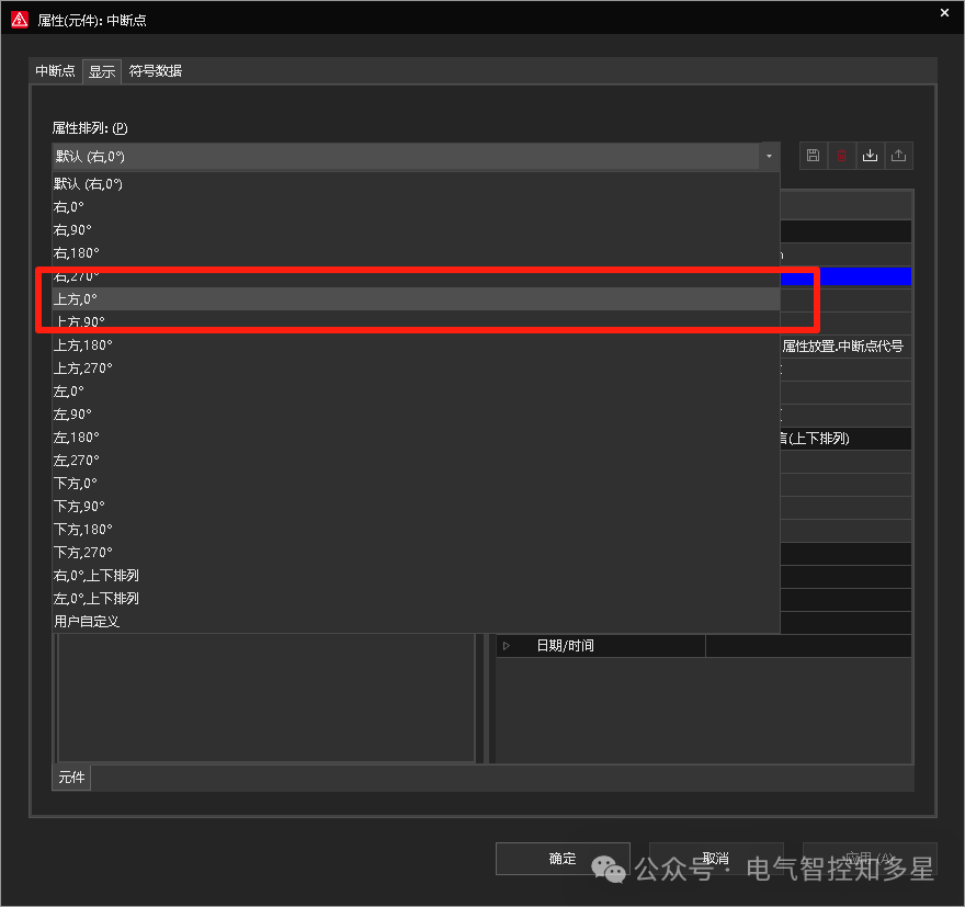
3. Insert a breakpoint, click the left side of the drawing – a properties window pops up – device display identifier – expand button – select 24V, in the display tab – property arrangement – top 0°.
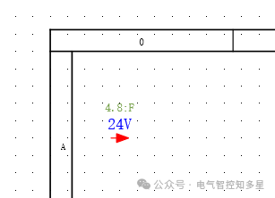
Connect the circuit.
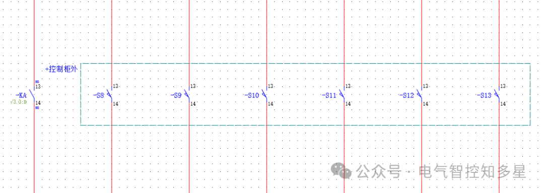
4. Insert a structural box, click the structural box, drag the mouse – S8-S13, a properties window pops up – device identifier – expand – modify the location code to outside the control cabinet.
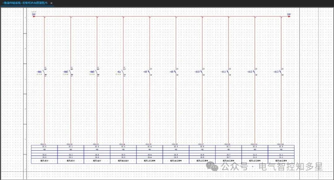
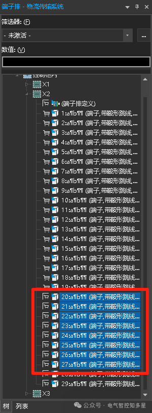
5. Add terminals for connecting devices inside and outside the control cabinet, as the limit switches -S8~-S13 are located outside the control cabinet and require terminals for connection. Project data – terminal block – navigator – logistics transmission system – control cabinet – X2 – terminals 20~27 – right-click – place.
Completion as shown:
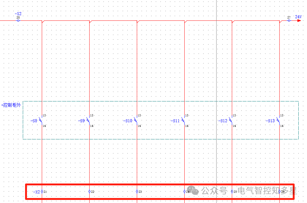
Task completed.