- Introduction
In some EMI testing items (such as RE), there may be cases where radiation exceeds standards due to SPI communication. A common solution is to add an RC filter to the SPI communication loop, which can attenuate high-frequency noise to improve radiation levels. However, adding an RC filter can affect the signal quality of the original communication, limiting the communication speed. Additionally, inappropriate RC parameters can lead to waveform quality that does not meet communication quality requirements, thus introducing additional communication issues.
- Considerations for Adding RC Filter to SPI
- The SPI communication speed; the higher the SPI communication speed, the higher the cutoff frequency of the RC filter. Generally, the cutoff frequency of the RC filter should be more than 10 times the communication frequency.
- It is necessary to clarify the quality requirements for SPI communication from the slave device. Generally, the receiving end has specific requirements for the rise time, fall time, and hold time of the signal.
- It is necessary to clarify the driving capability of the master device’s signal.
- The SPI RC filter parameters need to be placed in the appropriate position.
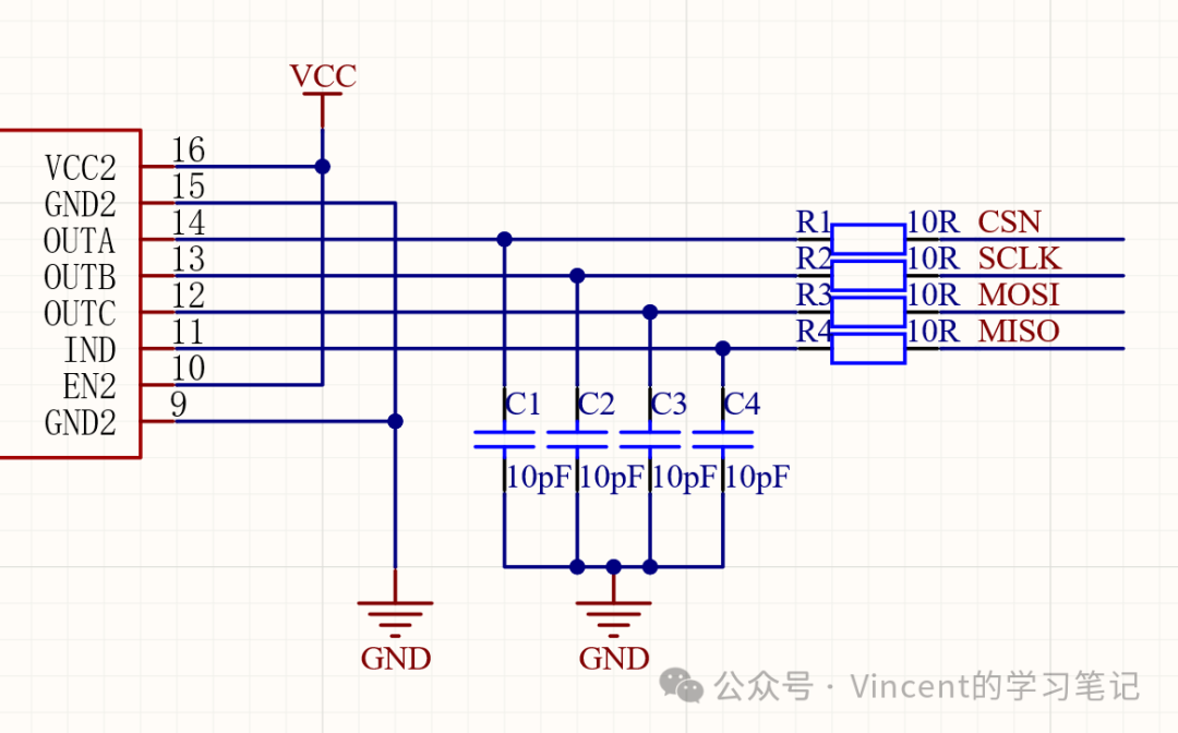
- The RC filter resistor should be placed at the transmitter end. The placement of the RC filter shown in the figure below is an incorrect example. Although this RC filter circuit suppresses communication waveform quality issues caused by parasitic impedance in the communication loop, for the CSN, SCLK, and MOSI signals, since the resistor R is not placed at the transmitter end, only the capacitor C and parasitic impedance are effective, failing to achieve the intended design purpose.
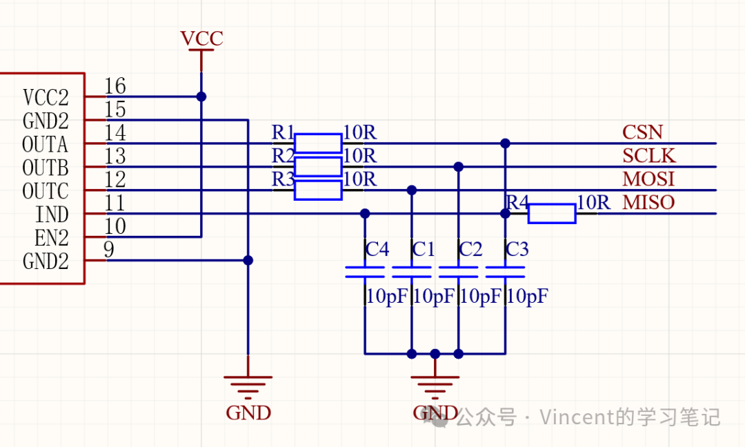
 The correct placement of the RC filter should be as shown in the figure below, where the resistors for CSN, SCLK, and MOSI should be placed close to the transmitter end to effectively filter and shape the SPU signal.
 5. Use an oscilloscope to measure the signal quality after adding the RC filter (whether noise has improved) and the timing (edge times, data delay relative to the clock).