Introduction to Modbus
Modbus is a serial communication protocol used to connect industrial automation devices, originally developed by Modicon in 1979. It has become one of the universal communication standards widely used in industrial automation scenarios.
Modbus adopts a master-slave model and supports various transmission methods, including serial (RS-232/485) and Ethernet versions (TCP/IP). It is mainly used for monitoring and controlling automation devices such as sensors, motors, and PLCs. It enables data exchange and control command transmission between devices, allowing them to coordinate their operations.
The Modbus protocol defines four types of storage areas: Coils, Discrete Inputs, Input Registers, and Holding Registers. Different types of storage areas correspond to different read and write operations.
| Storage Area Name | Data Type | Access Type | PLC Address | Register Address |
|---|---|---|---|---|
| Coils | Bit | Read/Write | 000001-065536 | 0-65535 |
| Discrete Inputs | Bit | Read Only | 100001-165536 | 0-65535 |
| Input Registers | Word | Read Only | 300001-365536 | 0-65535 |
| Holding Registers | Word | Read/Write | 400001-465536 | 0-65535 |
Each type of storage area has its own address range and read/write operation codes. Choose the appropriate storage area for read/write operations based on the application scenario.
For example, in Modbus TCP, the message structure is MBAP (Message Header) + PDU (Protocol Data Unit).
| Message Header | Frame Structure | ||||
|---|---|---|---|---|---|
| Transaction Identifier | Protocol Identifier | Length | Unit Identifier | Function Code | Data |
The Modbus protocol defines various function codes to implement read and write operations on storage areas. Below are some common function codes.
| Function Code | Function | Bit/Word Operation | Number of Operations |
|---|---|---|---|
| 01 | Read Coil Status | Bit Operation | Single or Multiple |
| 02 | Read Discrete Input Status | Bit Operation | Single or Multiple |
| 03 | Read Holding Registers | Word Operation | Single or Multiple |
| 04 | Read Input Registers | Word Operation | Single or Multiple |
| 05 | Write Single Coil | Bit Operation | Single |
| 06 | Write Single Holding Register | Word Operation | Single |
| 15 | Write Multiple Coils | Bit Operation | Multiple |
| 16 | Write Multiple Holding Registers | Word Operation | Multiple |
Assuming the slave address is 01H, and the starting address of the holding register to be read is 006BH, reading 2 registers, the command is as follows:
| Slave Address | Function Code | Starting Address High Byte | Starting Address Low Byte | Register Count High Byte | Register Count Low Byte |
|---|---|---|---|---|---|
| 01 | 03 | 00 | 6B | 00 | 02 |
Each holding register is 2 bytes long. The low address register is transmitted first, followed by the high address register. The high byte of each register data is transmitted first, followed by the low byte. The response is as follows:
| Slave Address | Function Code | Byte Count | 006BH High Byte | 006BH Low Byte | 006CH High Byte | 006CH Low Byte |
|---|---|---|---|---|---|---|
| 01 | 03 | 04 | 00 | 00 | 00 | 00 |
Why Bridge Modbus to MQTT
With the advent of Industry 4.0, the demand for intelligence, automation, and data in manufacturing is increasing. In this context, the Modbus protocol also faces some challenges.
Firstly, the Modbus protocol has significant security issues. Due to its relatively simple communication method, it is vulnerable to hacker attacks and data tampering.
Secondly, in terms of real-time performance and bandwidth utilization, the Modbus protocol is not as excellent compared to modern industrial communication standards. Especially in the case of large-scale device networking, traditional serial communication methods can no longer meet the requirements.
Additionally, in multi-layer architecture and cloud platform applications, the Modbus protocol has certain limitations. It can only perform point-to-point communication and does not well support distributed systems and cloud computing platforms.
Compared to Modbus, MQTT has clear advantages. The MQTT protocol is a lightweight message transmission protocol based on the publish/subscribe model, built on TCP/IP, and released by IBM in 1999. On October 29, 2014, MQTT became an officially approved communication standard by OASIS. It is now widely used in IoT, mobile internet, smart hardware, vehicle networking, smart cities, remote healthcare, electricity, oil, and energy sectors.
MQTT has the following main advantages:
-
Lightweight: MQTT is very lightweight and can be used in environments with limited bandwidth and poor network quality.
-
Flexibility: MQTT supports multiple connection methods and achieves flexible message delivery through the publish/subscribe model.
-
Reliability: MQTT ensures reliable message transmission, allowing reconnection and restoration of communication even if the network is interrupted.
-
Security: MQTT supports SSL/TLS encryption and authentication mechanisms to ensure data security.
Therefore, in the field of IoT, MQTT is more suitable for message transmission in distributed systems. Bridging Modbus to MQTT can leverage their strengths and complete an upgrade transformation.
Architecture for Bridging Modbus to MQTT
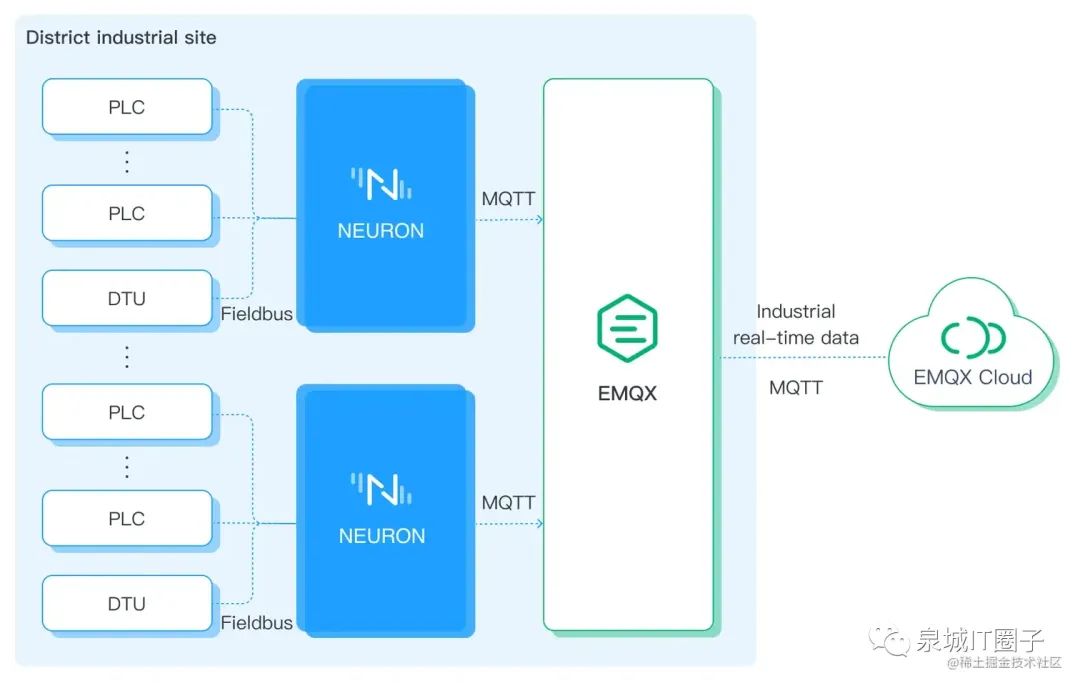
The Modbus data source sends data to the MQTT Broker, which receives and forwards it. This process requires two components: one is the edge device that converts the Modbus protocol to MQTT and sends it to the MQTT Broker; the other is an MQTT Broker that processes MQTT messages.
The Neuron from EMQ can convert the Modbus protocol to MQTT; EMQX can serve as an MQTT Broker to handle massive connections.
Neuron is a modern industrial IoT connection server that can connect various industrial devices using standard protocols or proprietary protocols, achieving interconnectivity between industrial IoT platforms and various devices. As a lightweight industrial protocol gateway software, Neuron can run on various resource-limited IoT edge hardware devices, aiming to solve the problem of difficult unified access to data from data-centric automated devices, providing foundational support for smart manufacturing.
EMQX is a large-scale, scalable, cloud-native distributed IoT MQTT message server. As the world’s most scalable MQTT message server, EMQX provides efficient and reliable connections for massive IoT devices, capable of high-performance real-time movement and processing of messages and event stream data, helping users quickly build IoT platforms and applications for critical businesses.
The following shows the architecture of Neuron collecting data from the edge and converting it to MQTT for uploading to the MQTT broker.
Bridging Modbus to MQTT with Neuron
This section will introduce how to use Neuron to collect data from Modbus devices, upload the collected data to the MQTT Broker (EMQX), and view it using MQTTX.
Quick Start with EMQX
EMQX provides various installation methods, and users can refer to the installation section for detailed installation methods. This example uses containerized deployment for the fastest experience with EMQX.
Run the following command to obtain the Docker image:
docker pull emqx/emqx:5.1.0Run the following command to start the Docker container:
docker run -d --name emqx -p 1883:1883 -p 8081:8081 -p 8083:8083 -p 8084:8084 -p 8883:8883 -p 18083:18083 emqx/emqx:5.1.0Access the EMQX Dashboard management console via your browser at http://localhost:18083/ (localhost can be replaced with your actual IP address) to manage device connections and monitor related metrics. This tutorial keeps the Docker running.
Initial username: admin, initial password: public
Installing the Modbus Simulator
Install the PeakHMI Slave Simulators software, which can be downloaded from the PeakHMI official website.
After installation, run the Modbus TCP slave EX. Ensure that Neuron and the simulator are running on the same local area network.
Click Windows->Register data to view the data.
Select site number 1.
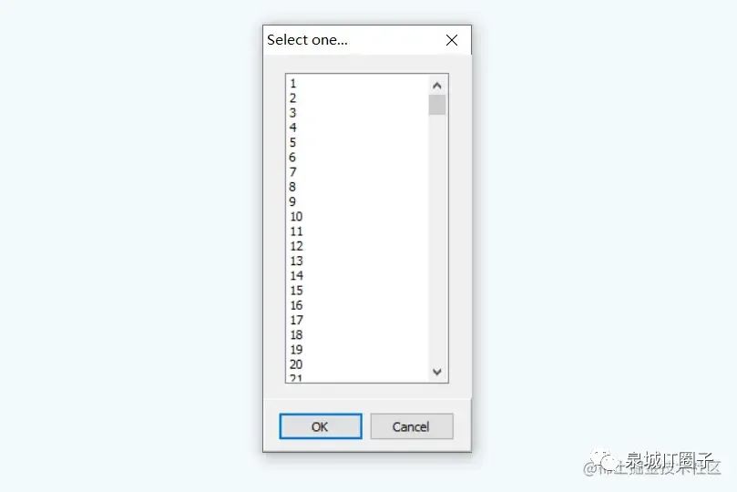
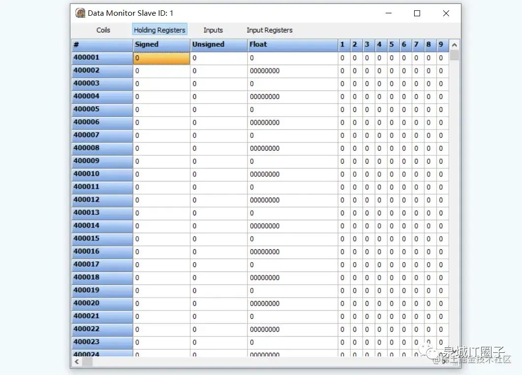
Select Holding Registers. At this point, the simulator has been successfully started, keep the simulator open and proceed to operate Neuron.
Quick Start with Neuron
Neuron provides various installation methods, and users can refer to the installation section for detailed installation methods. This example uses containerized deployment for the fastest experience with Neuron.
Get the Docker image:
$ docker pull emqx/neuron:latestStart the Docker container:
$ docker run -d --name neuron -p 7000:7000 --privileged=true --restart=always emqx/neuron:latestOpen a web browser, enter the gateway address and port number where Neuron is running to access the management console page, the default port number is 7000. Access http://localhost:7000/ (localhost can be replaced with your actual IP address)
Step One: Login
After the page opens, you will enter the login interface. Users can log in using the initial username and password (initial username: admin, initial password: 0000).
Step Two: Add Southbound Devices
In the Configuration menu, select Southbound Devices to enter the Southbound Devices interface, and click Add Device to add a new device.
-
Name: Enter the device name, for example, modbus-tcp-1;
-
Plugin: Select Modbus TCP from the dropdown.
Step Three: Set Southbound Device Parameters
After adding the southbound device, you will automatically enter the device configuration interface, fill in the parameters and submit.
-
Transmission Mode: Select TCP;
-
Connection Mode: Select Client;
-
Maximum Retry Count: Default 0;
-
Command Resend Interval: Default 0;
-
Command Send Interval: Default 20;
-
IP Address: Fill in the PC IP address where the PeakHMI Slave Simulators software is installed;
-
Port Number: Default 502;
-
Connection Timeout: Default 3000.
Step Four: Create Groups in Device Card
Click on any empty space in the device node card to enter the group list management interface, click Create to pop up the Create Group dialog. Fill in the parameters and submit:
-
Group Name: Enter the group name, for example, group-1;
-
Interval: Default 1000.
Step Five: Add Data Points in the Group
Click on any empty space in the group card to enter the point list management interface, click Create to enter the add point page.

Fill in the point parameters and submit:
-
Name: Enter the point name, for example, tag-1;
-
Attribute: Select point attribute from the dropdown, for example, Read, Write;
-
Type: Select data type from the dropdown, for example, INT16;
-
Address: Fill in the driver address, for example, 1!40001. 1 represents the point site number set in the Modbus simulator, and 40001 represents the point register address;
-
Description, multiplier, precision are not filled.
Step Six: View Collected Data in Data Monitoring
Select Monitoring → Data Monitoring to enter the data monitoring interface and view the values read from the created points, as shown below.
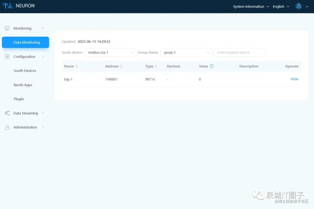
Note: Please ensure that the Modbus simulator is running.
The data monitoring displays values by group:
-
Southbound Device: Select the desired southbound device from the dropdown, for example, select the created modbus-tcp-1;
-
Group Name: Select the group under the selected southbound device from the dropdown, for example, select the created group-1;
-
After selection, the page will display the values of all points in the group that have been read.
Step Seven: Add Northbound Plugin Module for Applications
Create a northbound application, Neuron establishes a connection with the northbound application and uploads the collected device data to the MQTT Broker (EMQX).
In the Configuration menu, select Northbound Applications, click Add Application, as shown in the figure below.
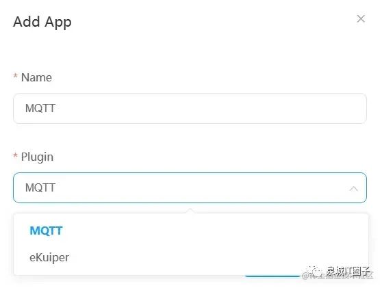
Add an MQTT cloud connection module:
-
Name: Enter the application name, for example, MQTT;
-
Plugin: Select MQTT plugin from the dropdown.
Step Eight: Set Northbound Application Parameters
After adding the northbound application, you will automatically enter the application configuration interface, fill in the parameters and submit.
Set the MQTT connection:
-
Client ID: Note that this ID must be unique; duplicate IDs will cause the client to be kicked off. For example, set it to MQTT1999;
-
QoS Level: Default is 0;
-
Data Reporting Format: Default is Values-format;
-
Write Request Topic: Default is /neuron/MQTT/write/req;
-
Write Response Topic: Default is /neuron/MQTT/write/resp;
-
Offline Cache: Default is off;
-
Server Address: Fill in the address of the created EMQX broker, which is the address where EMQX is deployed (localhost, i.e., your actual IP address).
-
Server Port: Default is 1883;
-
Username, Password: Leave blank;
-
SSL: Default is off.
Step Nine: Subscribe to Southbound Point Group
Click on any empty space in the newly created MQTT application node card to enter the subscription group interface, click Add Subscription.
Subscribe to the data group of the southbound device:
-
Southbound Device: Select the created southbound device from the dropdown, for example, modbus-tcp-1;
-
Group: Select the group to subscribe to from the dropdown, for example, group-1;
-
Topic: MQTT topic, in this example, default is /neuron/MQTT/group-1. Next, subscribe to this topic in MQTTX to receive messages.
Step Ten: View Data in MQTT Client
After subscribing, in addition to the data monitoring interface of neuron itself, users can use the MQTT client – MQTTX to connect to EMQX to view the reported data.
After starting MQTTX, click + New Connection on the main page, fill in the configuration parameters, and click connect in the upper right corner.
-
Name: Name the message for easy viewing, for example, name it modbus-tcp;
-
Client ID: Use the default value to ensure the ID is unique;
-
Server Address: Select ws://,
emqx@localhost(localhost can be replaced with your actual IP address); -
Port: 8083.
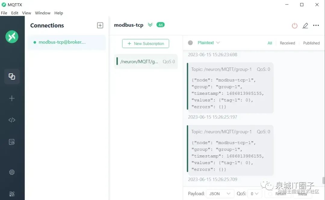
Other parameters are optional, click connect in the upper right corner after completion. After a successful connection, subscribe to the topic.
-
Click Add Subscription, Topic is consistent with the one in step nine. For example, fill in
/neuron/MQTT/group-1.
After successful subscription, you can see that MQTTX continuously receives data collected and reported by Neuron. As shown in the figure below.
Industrial IoT Application Scenarios
Oil Production Data Collection
With the expansion of digital construction in oil production, the number of automated devices is also increasing, leading to complexity in data collection and management.
The device side connects various industrial devices through the edge industrial protocol gateway software Neuron, allowing unified collection of data from DTUs, RTUs, and various types of PLCs in the oil production environment. At the same time, during the data reporting process, unified planning of collection points, collection frequency, reporting frequency, and reporting format is achieved, facilitating storage and data consumption by upper-level business systems.
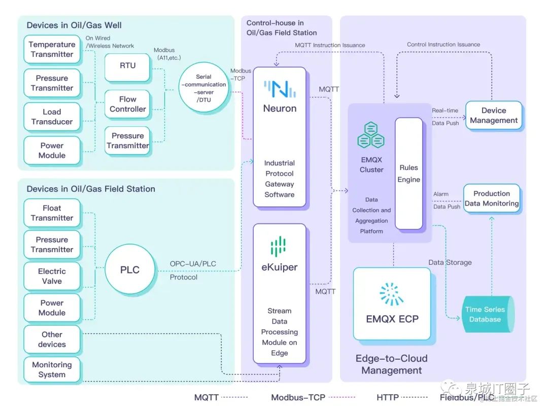
Combining Neuron with EMQX, eKuiper, EMQX-ECP, and other EMQ products can bring the following benefits to the oil industry:
-
Light frontend, heavy backend system architecture, reducing on-site device and system operation and maintenance costs.
-
Based on IoT protocols as the main means of data collection and transmission, achieving low-latency real-time reporting of production data and improving business response capabilities.
-
Solving the real-time unified aggregation of massive heterogeneous devices and systems, realizing the unified aggregation storage of data from various types of production and monitoring devices, effectively integrating data assets.
-
Through a unified access platform and the rich data interfaces provided by the platform, achieving decoupling of data collection and data consumption systems, making application development more convenient and efficient.
Empowering Industrial Networking, Digitalization, and Intelligence
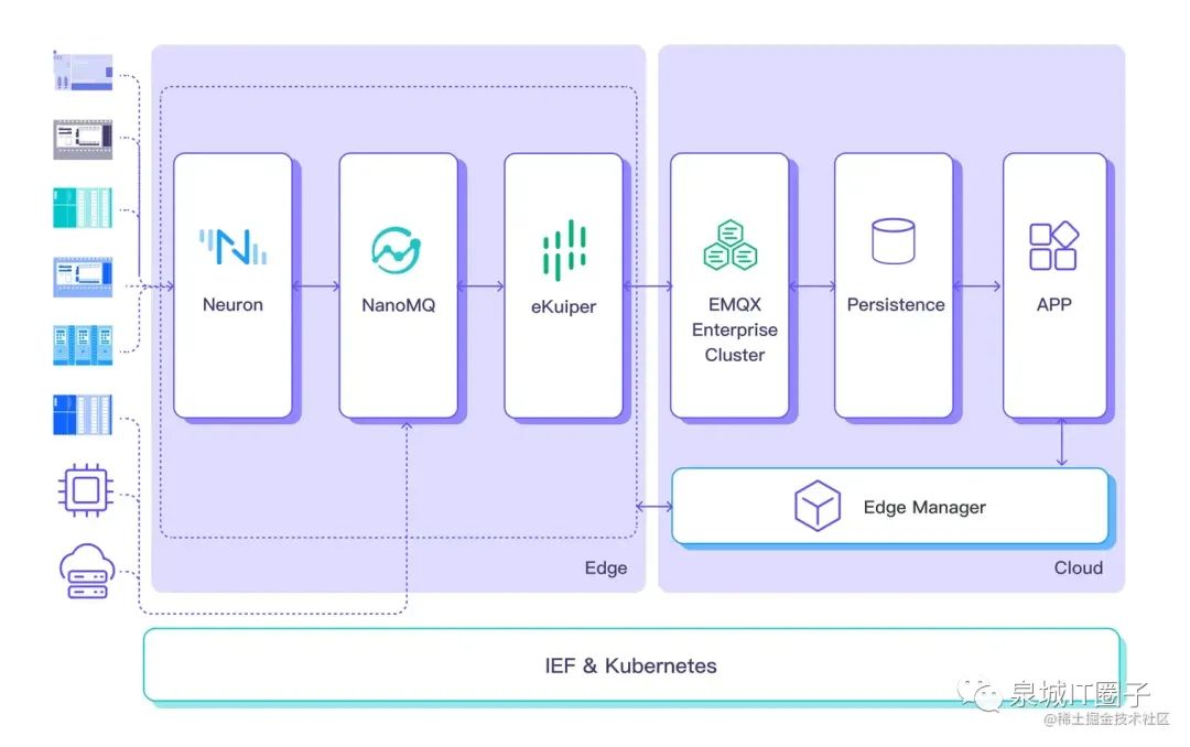
A unified one-stop industrial IoT data platform becomes crucial in the context of Industry 4.0.
Neuron can support complete industrial protocols such as Modbus, OPC-UA, IEC61850, IEC104, enabling efficient access to data from various heterogeneous industrial devices. The lightweight edge stream processing engine eKuiper performs collection, filtering, completion, and time window calculations at the edge, providing high-quality data sources for edge AI inference services.
By achieving real-time data connection, mobility, storage, processing, and analysis in the cloud, a solid data foundation is laid for big data analysis and artificial intelligence applications, enabling enterprises to quickly develop upper-level applications.
Conclusion
Using the Modbus protocol enables communication and data exchange between devices, while MQTT provides an efficient, flexible, and secure message transmission mechanism. By converting Modbus RTU or TCP to MQTT messages, device data can be easily sent to the cloud for remote control and monitoring when needed. This approach helps industrial enterprises better manage their devices and production processes, improving production efficiency and quality.
Copyright Statement: This article is original to EMQ, please indicate the source when reprinting.
Original link: www.emqx.com/zh/blog/bri…
Author: EMQX link: https://juejin.cn/post/7266439610330775563