Why is the BLE protocol stack layered? How to understand BLE “connection”? What would happen if the BLE protocol only had the ATT layer and no GATT layer?
1. Protocol Stack Framework
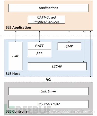
Generally speaking, we refer to the implementation code of a protocol as a protocol stack. The BLE protocol stack is the code that implements the Low Energy Bluetooth protocol. Understanding and mastering the BLE protocol is a prerequisite for implementing the BLE protocol stack. Before diving into the various components of the BLE protocol stack, let’s first take a look at the overall architecture of the BLE protocol stack.
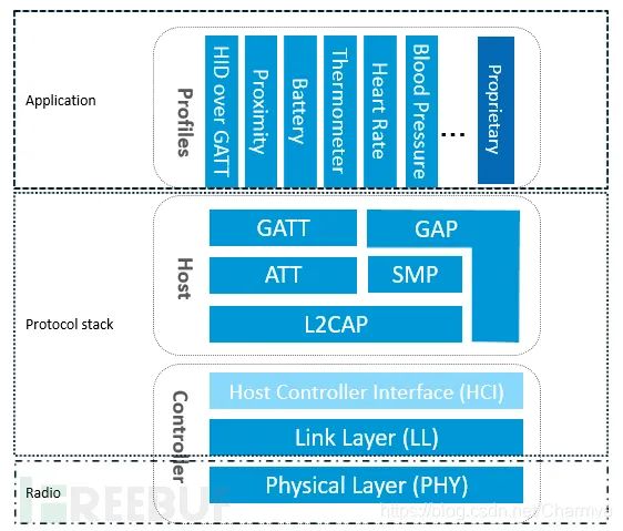
As shown in the figure above, to implement a BLE application, you first need a chip that supports BLE radio frequency, then you need to provide a BLE protocol stack that matches this chip, and finally develop your application on top of the protocol stack. It can be seen that the BLE protocol stack is the bridge connecting the chip and the application, and it is the key to implementing the entire BLE application. So what specific functions does the BLE protocol stack include? Simply put, the BLE protocol stack is mainly used to encapsulate your application data layer by layer to generate an air data packet that meets the BLE protocol, meaning it wraps the application data in a series of headers and tails. Specifically, the BLE protocol stack mainly consists of the following components:
PHY Layer (Physical Layer). The PHY layer specifies the radio frequency band used by BLE, modulation and demodulation methods, etc. The performance of the PHY layer directly determines the power consumption, sensitivity, and selectivity of the entire BLE chip.
LL Layer (Link Layer). The LL layer is the core of the entire BLE protocol stack and also its difficulty and focus. For example, Nordic’s BLE protocol stack can support 20 links simultaneously, thanks to the LL layer. The LL layer has a lot of responsibilities, such as choosing which RF channel to communicate on, how to identify air data packets, when to send packets, ensuring data integrity, how to receive ACKs, how to retransmit, and how to manage and control the link, among others. The LL layer is only responsible for sending or receiving data; how to parse the data is left to the GAP or GATT layers above.
HCI (Host Controller Interface). HCI is optional (see the article: Three Bluetooth Architecture Implementation Schemes (Bluetooth Protocol Stack Solutions) for details). HCI is mainly used for cases where two chips implement the BLE protocol stack, to standardize the communication protocols and commands between them.
GAP Layer (Generic Access Profile). GAP is one of the two ways to parse the LL layer payload (effective data packet), and it is the simpler of the two. GAP simply standardizes and defines the LL payload, so the functionalities that GAP can achieve are extremely limited. Currently, GAP is mainly used for broadcasting, scanning, and initiating connections.
L2CAP Layer (Logical Link Control and Adaptation Protocol). L2CAP provides a simple encapsulation of LL; LL only cares about the data being transmitted, while L2CAP distinguishes between encrypted channels and ordinary channels, and also manages connection intervals.
SMP (Security Manager Protocol). SMP is used to manage the encryption and security of BLE connections, ensuring connection security without affecting user experience, which are the tasks SMP needs to consider.
ATT (Attribute Protocol). In simple terms, the ATT layer is used to define user commands and the data for command operations, such as reading or writing certain data. In the BLE protocol stack, developers most frequently interact with the ATT layer. BLE introduces the concept of attributes to describe individual data points. Attributes not only define data but also the ATT commands that can be used with that data, which is why this layer is called the ATT layer.
GATT (Generic Attribute Profile). GATT standardizes the data content within attributes and uses the concept of groups to classify and manage attributes. Without GATT, the BLE protocol stack could still function, but interoperability would be problematic. It is precisely because of GATT and various application profiles that BLE has overcome the compatibility issues faced by wireless protocols like ZigBee, becoming the most widely shipped 2.4G wireless communication product.
I believe many people still do not understand how the BLE protocol stack works and what each layer does specifically, or why it is layered as such after reading the above introduction. Below, I will explain how the layers of the BLE protocol stack closely cooperate to accomplish the task of sending a data packet, using the example of how to send a data packet.
2. How to Send a Data Packet Wirelessly
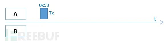
Assume there are devices A and B, and device A wants to send its current battery status of 83% (represented in hexadecimal as 0x53) to device B. How should it do this? As a developer, he hopes for simplicity; he wants to be able to accomplish this task with a simple API call, such as send(0x53). In fact, our BLE protocol stack is designed this way, allowing developers to simply call send(0x53) to send the data, while the rest is handled by the BLE protocol stack. Many people might wonder if the BLE protocol stack directly sends 0x53 at the physical layer, as shown in the figure below:
This method seems appealing at first glance, but since many details are not considered, it is not feasible in practice. First, it does not consider which RF channel to use for transmission. Without changing the API, we can only layer the protocol stack, which leads us to introduce the LL layer. The developer still calls send(0x53), but now it becomes send_LL(0x53,2402M) (note: 2402M is the channel frequency). There is another issue: how does device B know that this data packet is intended for it or someone else? To address this, BLE introduces the access address concept to indicate the recipient’s identity, among which 0x8E89BED6 is a special access address that indicates the packet is to be sent to all surrounding devices, i.e., broadcasting. If you want to communicate one-on-one (what the BLE protocol refers to as a connection), meaning that device A’s data packet can only be received by device B and vice versa, then a unique random access address must be generated to identify the connection between device A and device B.
2.1 Broadcasting
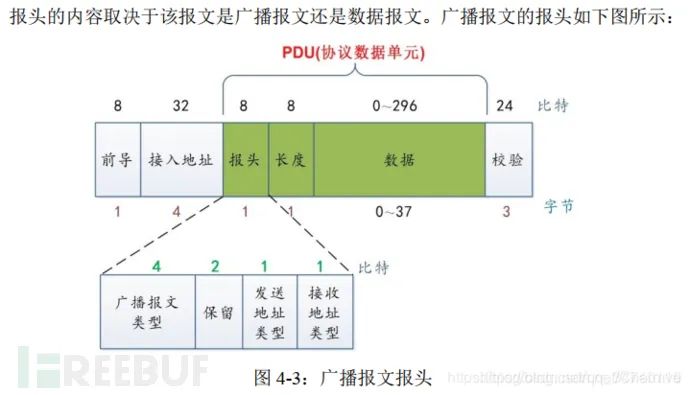
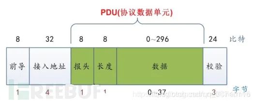
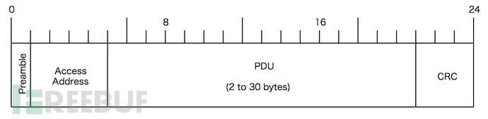
First, let’s look at a simple broadcasting scenario. In this case, we call device A the advertiser and device B the scanner or observer. In broadcasting mode, device A’s LL layer API will change to send_LL(0x53,2402M, 0x8E89BED6). Since device B can receive broadcasts from many devices simultaneously, the data packet must also contain device A’s device address (0xE1022AAB753B) to confirm that the broadcast packet comes from device A. Therefore, the parameters for send_LL need to change to (0x53,2402M, 0x8E89BED6, 0xE1022AAB753B). The LL layer also needs to check the integrity of the data, that is, whether the data has been tampered with during transmission; for this purpose, CRC24 is introduced to verify the data packet (assumed to be 0xB2C78E). Additionally, to enhance the efficiency of the modulation and demodulation circuit, a byte of preamble is added to the front of each data packet, which is typically 0x55 or 0xAA. Thus, the entire air packet becomes: (Note: the air packet is represented in little-endian format!)
This data packet also has the following issues:
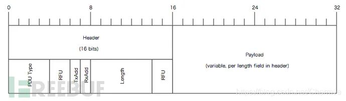
There is no classification or organization of the data packet, so device B cannot find the data it wants, 0x53. Therefore, we need to add two fields after the access address: the LL header and the length byte. The LL header indicates the type of the data packet, and the length byte indicates the length of the payload.
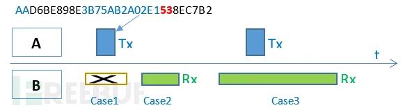
When should device B open its RF window to receive the air data packet? As shown in the figure case 1, when device A’s data packet is being transmitted in the air, device B has its receiving window closed, and the communication will fail. Similarly, in case 2, when device A is not sending a data packet in the air, device B has its receiving window open, and the communication will also fail. Only in case 3 can the communication succeed, meaning that when device A’s data packet is being transmitted in the air, device B has its RF receiving window open at the right moment; thus, the communication can succeed. In other words, the LL layer must also define the communication timing.
After device B receives the data 0x53, how should it parse this data? Does it represent humidity, battery level, or something else? This is the job of the GAP layer, which introduces the LTV (Length-Type-Value) structure to define data. For example, 020105, where 02 is length, 01 is type (mandatory field indicating broadcast flag; this field must be included in the broadcast packet), and 05 is the value. Since the maximum size of the broadcast packet is limited to 31 bytes, the types of data it can define are extremely limited. For the battery level mentioned here, GAP has not defined it, so to send battery level data via broadcasting, it can only use a vendor-defined data type 0xFF, i.e., 04FF590053, where 04 indicates length, FF indicates data type (custom data), 0x0059 is the vendor ID (mandatory field in custom data), and 0x53 is our data (the two devices agree that 0x53 represents battery level and not something else).
The final data packet transmitted over the air will become:
AAD6BE898E600E3B75AB2A02E102010504FF5900538EC7B2
AA – Preamble
D6BE898E – Access Address
60 – LL Frame Header Field
0E – Payload Length
3B75AB2A02E1 – Advertiser Device Address
02010504FF590053 – Broadcast Data
8EC7B2 – CRC24 Value

Details about the third part of the header will be introduced later.
With the PHY, LL, and GAP layers, we can send broadcast packets, but the information carried by broadcast packets is extremely limited and has the following major limitations:
Cannot perform one-to-one bidirectional communication (broadcasting is one-to-many communication and unidirectional).
Due to the lack of support for packaging and unpackaging, large data cannot be transmitted.
Communication is unreliable and inefficient. The broadcast channel cannot be too many; otherwise, it will lead to low efficiency in the scanning end. Therefore, BLE only uses channels 37 (2402MHz), 38 (2426MHz), and 39 (2480MHz) for broadcasting and scanning, so broadcasting does not support frequency hopping. Since broadcasting is one-to-many, it also cannot support ACK. All these make broadcast communication unreliable.
High power consumption on the scanning end. Since the scanning end does not know when the device side broadcasts or which channel is used for broadcasting, the scanning end can only extend the scanning window time and simultaneously scan the three channels 37/38/39, which results in higher power consumption.
However, connecting can effectively solve the above issues. Next, let’s see how a connection sends 0x53.
2.2 Connection Mode
What exactly is a connection? Like wired UART, which is easy to understand, it connects device A and device B with wires (Rx and Tx, etc.). Connecting devices using wires actually allows both devices to have a common communication medium and synchronize their clocks. The same principle applies to Bluetooth connections; establishing a Bluetooth connection between device A and device B means that both devices have successfully synchronized one-on-one, which includes the following aspects:
-
Devices A and B agree on the physical channel to be used next.
-
Devices A and B establish a common time anchor, meaning that both parties’ time origins become the same point.
-
Devices A and B successfully synchronize their clocks, meaning both parties know when to send and receive data packets.
Once the connection is established, the communication process between devices A and B is as follows:
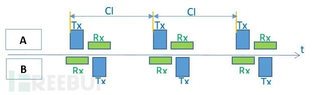
As shown in the figure above, once device A and device B are successfully connected (in this case, we refer to device A as the Master or Central, and device B as the Slave or Peripheral), device A will periodically send data packets to device B at intervals defined by CI (connection interval), while device B will also periodically open its RF receiving window at CI intervals to receive data packets from device A. Additionally, according to Bluetooth specifications, 150us after device B receives a data packet from device A, device B switches to sending mode to send its data to device A; device A then switches to receiving mode to receive the data sent by device B. Thus, in a connection state, the RF sending and receiving windows of devices A and B are both periodically opened and closed in a planned manner, and the open time is very short, greatly reducing system power consumption and significantly improving system efficiency.
Now let’s see how data 0x53 is sent in the connection state, from which everyone can appreciate the cleverness of the layered BLE protocol stack.
For developers, it is very simple; they only need to call send(0x53).
The GATT layer defines the type and grouping of the data. For convenience, we use 0x0013 to represent the battery level data type, so the GATT layer packages the data into 130053 (little-endian format!).
The ATT layer is used to select specific communication commands, such as read/write/notify/indicate, etc. Here, we choose the notify command 0x1B, so the data packet becomes: 1B130053.
The L2CAP layer specifies the connection interval (CI), for example, synchronizing every 10ms (CI is not reflected in the data packet) and specifies the logical channel number 0004 (indicating ATT command), and finally adds the ATT data length 0x0004 to the header, resulting in the data becoming: 040004001B130053.
The LL layer has many tasks. First, LL needs to specify which physical channel to use for transmission (the physical channel is not reflected in the data packet), then allocate an Access Address (0x50655DAB) for this connection to indicate that this connection is exclusively for device A and device B, followed by adding the LL header and payload length fields. The LL header indicates that this packet is a data packet, not a control packet, etc., and the payload length indicates the total length of the L2CAP field, finally adding the CRC24 field to ensure the integrity of the entire packet.
So the final data packet becomes: AAAB5D65501E08040004001B130053D550F6.
AA – Preamble
0x50655DAB – Access Address
1E – LL Frame Header Field
08 – Payload Length
04000400 – ATT Data Length and L2CAP Channel Number
1B – Notify Command
0x0013 – Battery Data Handle
0x53 – The actual battery data to be sent
0xF650D5 – CRC24 Value
Although the developer only called send(0x53), due to the layered packaging of the Low Energy Bluetooth protocol stack, the actual data transmitted over the air will look as shown in the figure below, which satisfies both the communication requirements of Low Energy Bluetooth and simplifies the user API, achieving a dual purpose!

Details about the third part of the header will be introduced later.
The above is just a simple overview of the implementation principles of the BLE protocol stack. Even so, since these are all about the lower-level aspects of the BLE protocol stack, many developers may still find it rather tedious and obscure. Moreover, for many developers, they are not concerned with how the BLE protocol stack is implemented; they are more concerned with how to use the BLE protocol stack, i.e., how to develop a BLE application. BLE applications are tangible things that cannot be discussed vaguely like the protocol stack above; they must be explained in conjunction with specific Bluetooth chips and Bluetooth protocol stacks. Therefore, the subsequent sections will take Nordic chips and protocol stacks as examples to explain how to develop BLE applications and how to understand some concepts and terms defined in the BLE protocol through code.
Tags: ATT, GAP, Link layer, GATT, L2CAP, BLE stack, broadcasting, connection, BLE protocol stack, link layer
3. PHY and LL Layer Protocol Stack Writing
3.1 Basic Concepts
(1) Link Layer State Machine
There are 5 states:
Ready state: Central state; any state can transition to it;
Broadcasting state: Using broadcast messages
Scanning state: Using broadcast messages, non-connectable
Initiating state: Using broadcast messages, randomly initiating connections
Connection state: Using data messages;
(2) Protocol Stack
For protocol stack content, please refer to: Understanding Bluetooth Advertising Packets.
Chinese version: http://blog.csdn.net/ooakk/article/details/7302425
(3) Communication Channels
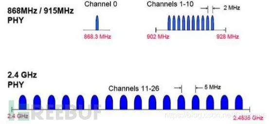
BLE operates in the ISM band and defines two frequency bands: the 2.4GHz band and the 896/915MHz band. A total of 27 channels are specified in IEEE802.15.4:
In the 2.4GHz band, there are 16 channels, with a channel communication rate of 250kbps:
In the 915MHz band, there are 10 channels, with a channel communication rate of 40kbps:
In the 868MHz band, there is 1 channel, with a channel communication rate of 20kbps.

BLE operates in the 2.4GHz band and only uses 3 broadcast channels, utilizing adaptive frequency hopping technology that is common to all Bluetooth specification versions.
Bluetooth has 79 RF channels, numbered from 0 to 78, starting at 2402 MHz and separated by 1 MHz.
BTLE has 40 channels (also known as channels), with channel 37 as the first, followed by 0-36, and then channel 39.
Due to space limitations, the specific implementation of the protocol stack will be discussed in subsequent content.

Exciting Recommendations