Ways of Communication Between Devices
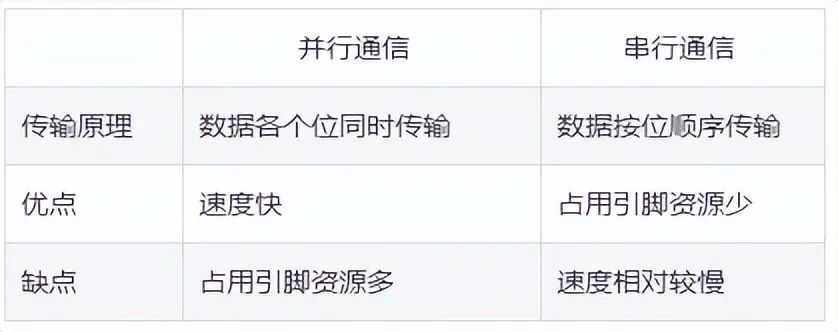
Generally, the communication methods between devices can be divided into parallel communication and serial communication. The differences between parallel and serial communication are shown in the table below.
Classification of Serial Communication
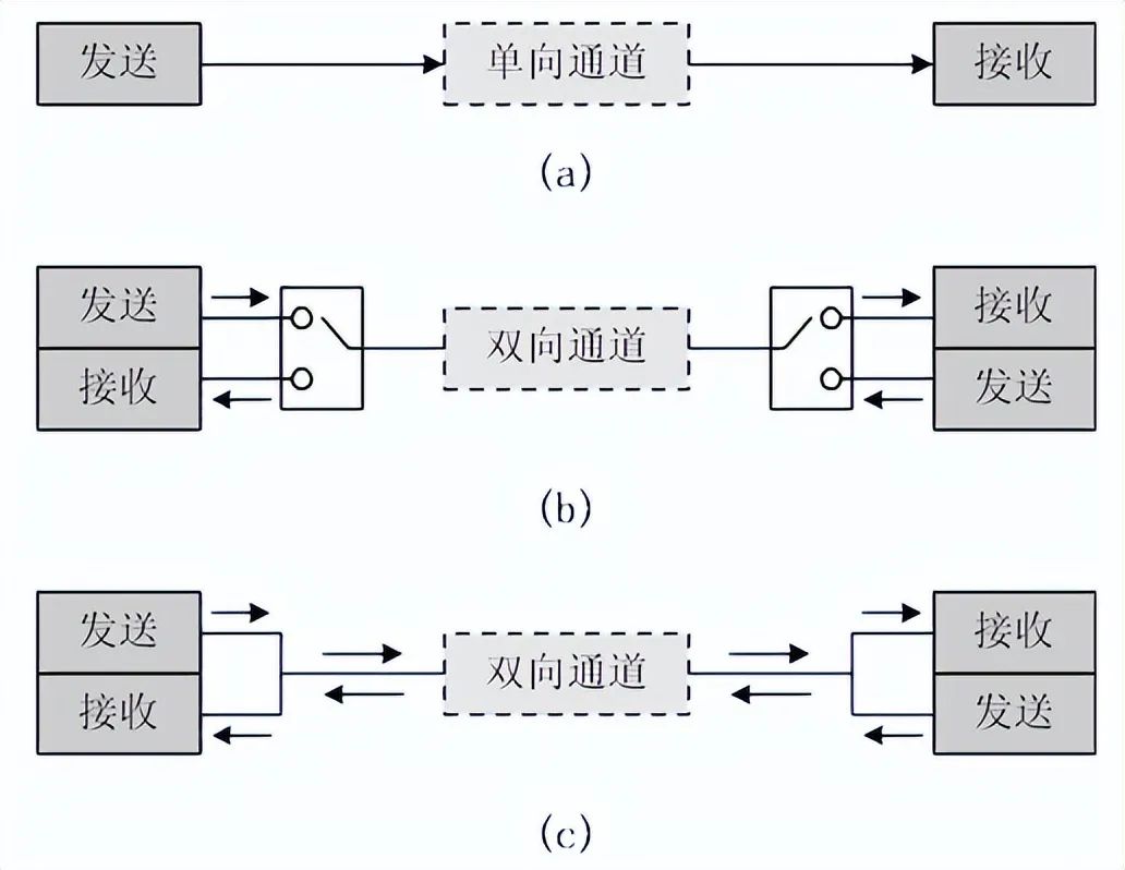
1. According to the direction of data transmission, it can be divided into:
-
Simplex: Data transmission only supports data transmission in one direction;
-
Half-Duplex: Allows data to be transmitted in both directions. However, at any given moment, data can only be transmitted in one direction; it is essentially a switching direction simplex communication; it does not require independent receiving and transmitting ends, and both can use one port together.
-
Full-Duplex: Allows data to be transmitted simultaneously in both directions. Therefore, full-duplex communication is a combination of two simplex communication methods, requiring independent receiving and transmitting ends.
2. According to the communication method, it can be divided into:
-
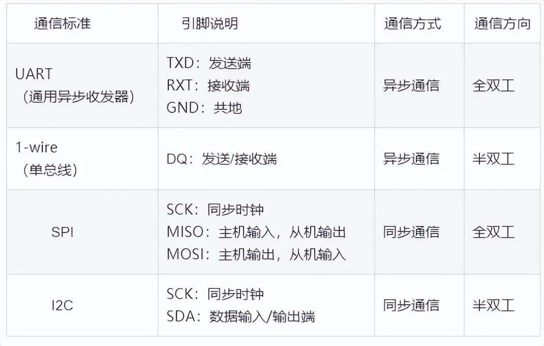
Synchronous Communication: Data is transmitted with clock synchronization signals. For example: SPI, IIC communication interfaces.
-
Asynchronous Communication: No clock synchronization signals are used. For example: UART (Universal Asynchronous Receiver-Transmitter), Single Bus.
In synchronous communication, a signal line is used to transmit signals above the transceiving devices, and both sides coordinate and synchronize data under the drive of the clock signal. For example, it is usually stipulated that data lines are sampled on the rising or falling edge of the clock signal during communication.
In asynchronous communication, no clock signals are used for data synchronization; instead, some signal bits used for synchronization are interspersed directly within the data signal, or the subject data is packaged in data frame format for transmission. Both parties also need to agree on the data transmission rate (i.e., baud rate) to better synchronize. Common baud rates include 4800bps, 9600bps, 115200bps, etc.
In synchronous communication, most of the content transmitted by the data signal is valid data, while asynchronous communication includes various identifiers of the data frame. Therefore, synchronous communication is more efficient, but the clock of both sides in synchronous communication allows for smaller errors; even slight clock errors can lead to data confusion, while asynchronous communication allows for larger clock errors.
Common Serial Communication Interfaces
Basics of STM32 Serial Communication
STM32 has two types of serial communication interfaces: UART (Universal Asynchronous Receiver-Transmitter) and USART (Universal Synchronous/Asynchronous Receiver-Transmitter). For the high-capacity STM32F10x series chips, there are 3 USARTs and 2 UARTs.
UART Pin Connection Method
-
RXD: Data input pin, for receiving data;
-
TXD: Data output pin, for sending data.
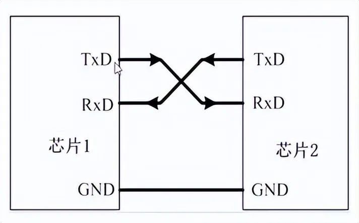
For the connection between two chips, both chips must share a common ground (GND), and TXD and RXD should be crossed. Here, crossing means that chip 1’s RXD connects to chip 2’s TXD, and chip 2’s RXD connects to chip 1’s TXD. This allows TTL level communication between the two chips. For examples of STM32 serial communication with the 51 microcontroller, please visit: STM32 and 51 Microcontroller Serial Communication Example.
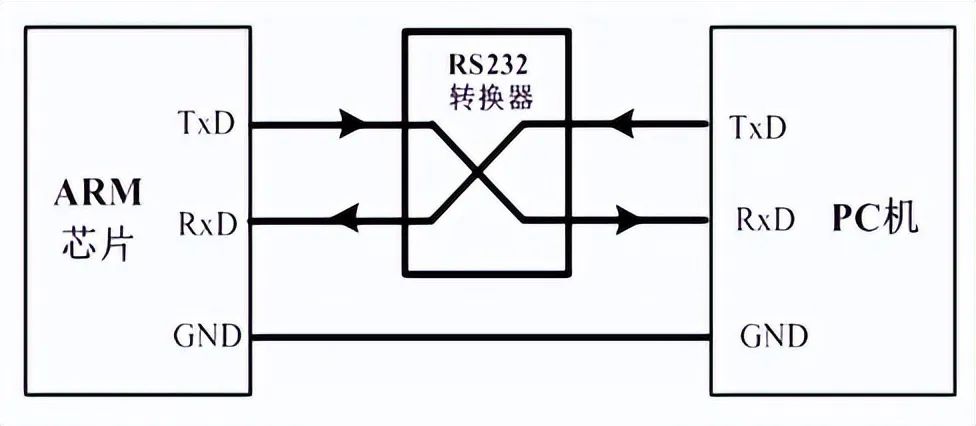
If the chip is connected to a PC (or host), besides sharing a ground, direct crossing connections cannot be made. Although both the PC and the chip have TXD and RXD pins, the PC (or host) usually uses an RS232 interface (usually in DB9 packaging), thus direct crossing connections cannot be made. The RS232 interface has 9 pins (or pins), and the TXD and RXD are obtained through level conversion. Therefore, to enable direct communication between the chip and the PC’s RS232 interface, the chip’s input and output ports must also be level converted to RS232 type before crossing connections.
After level conversion, the voltage standards for the chip’s serial port and RS232 are different:
-
Microcontroller’s voltage standard (TTL level): +5V represents 1, 0V represents 0;
-
RS232 voltage standard: +15/+13 V represents 0, -15/-13 represents 1.
The communication structure diagram for devices using the RS-232 communication protocol standard is shown below:
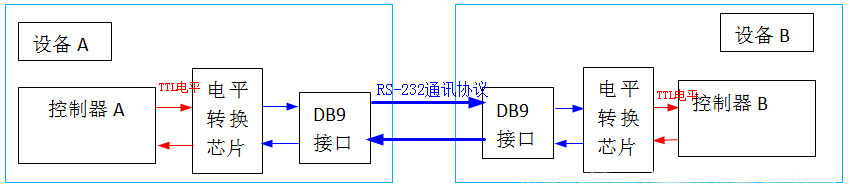
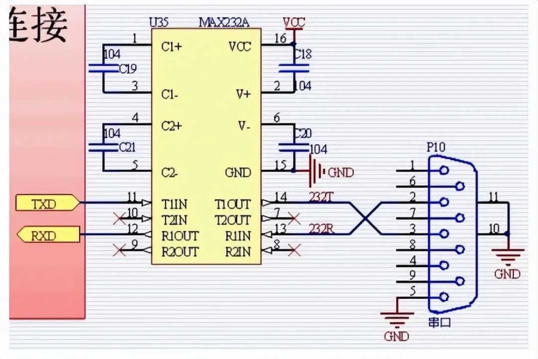
Therefore, the connection between the microcontroller’s serial port and the PC’s serial port should follow the connection method below: between the microcontroller’s serial port and the RS232 port provided by the host, a level conversion circuit (such as the Max232 chip in the diagram below) is used to implement the conversion between TTL level and RS232 level. For examples of communication between STM32 and PC, please visit: STM32 Example – Control Serial Data Transmission with a Key, code included at the end.
Introduction to RS232 Serial Port
The 9-pin interface at the back of a desktop computer is the COM port (serial port), which is widely used in industrial control and data acquisition. In the above image, the rightmost port is the serial port interface commonly referred to as the RS232 interface, which is commonly in DB9 packaging.
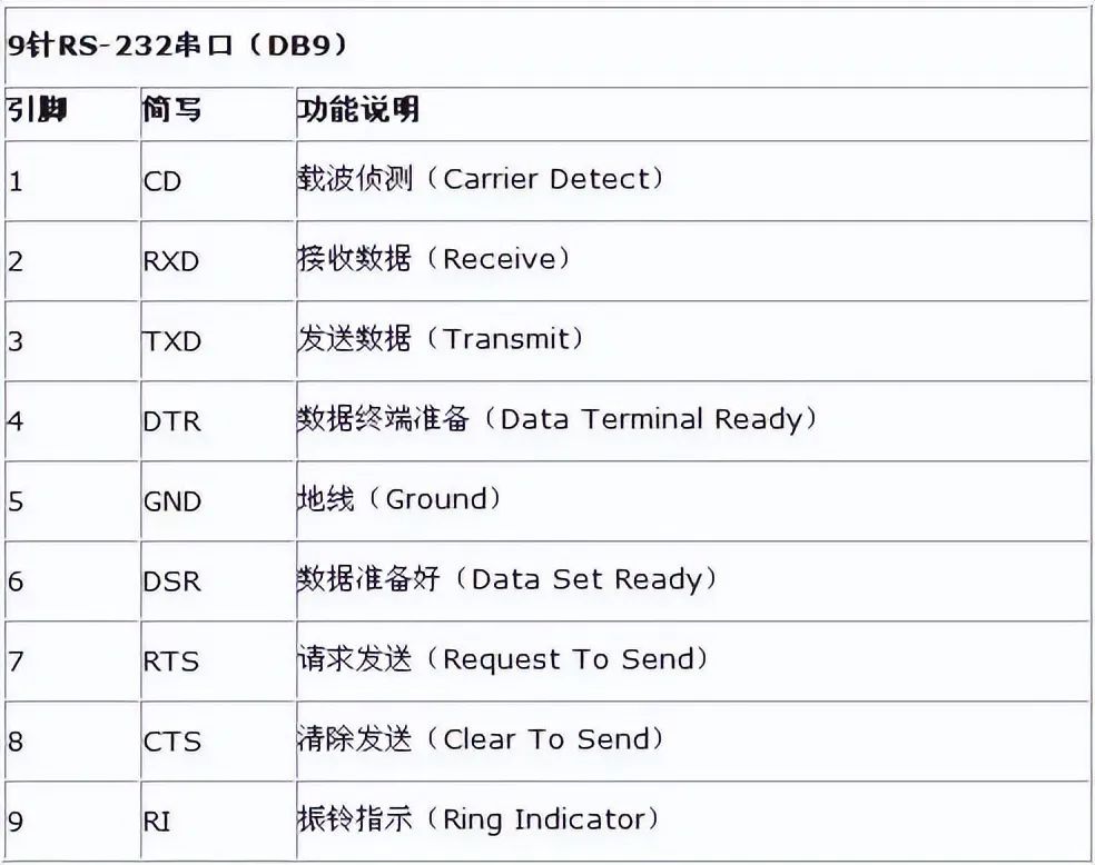
Only two pins participate in communication during the process.
-
Pin 2: Computer input RXD
-
Pin 3: Computer output TXD. Through pins 2 and 3, full-duplex (simultaneous sending and receiving) serial asynchronous communication can be achieved.
-
Pin 5: Ground.
The microcontroller’s P3 port has two multiplexed interfaces RXD and TXD. This is the transceiver port for serial communication, and the connection should be offset to correspond to the computer’s TDX and RDX. Note: The voltage standards of the microcontroller and RS232 are different.
The voltage standard of the microcontroller is TTL level: +5V represents 1, 0V represents 0.
The voltage standard of RS232: +15/+13 V represents 1, -15/-13 represents 0.
Therefore, the connection method for serial communication between the microcontroller and the computer should follow the connection method below:
A level conversion circuit (the Max232 chip in the top image) is used to convert between TTL level and RS232 level between the microcontroller and the RS232 port provided by the host. The connection method diagram between the PC serial port and the microcontroller serial port is shown below:

Note that these two DB9 connectors: DB91 is on the computer, and DB92 is soldered on the microcontroller experimental board.
The crossing connection means that DB91’s RXD connects to DB92’s TXD.
DB92’s RXD connects to DB91’s TXD, thus crossing the connection. If the computer does not have an RS232 port and only has a USB port, a serial port adapter can be used to convert to a serial port, as shown in the diagram below.
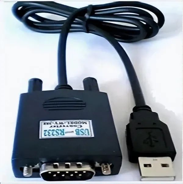
At this time, a serial port driver program needs to be installed on the computer host.
Note that this driver program drives the PL2303 chip (inside the large head in the image) to convert RS232 information into USB information.
The diagram below shows the internal structure of the above image:
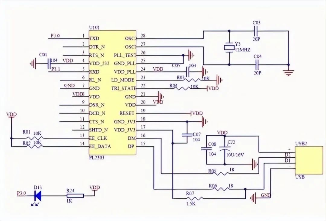
Serial communication is simpler than USB because it does not have a protocol and is easy to use.
Features of STM32 UART
-
Full-duplex asynchronous communication;
-
Fractional baud rate generator system provides precise baud rates. The shared programmable baud rate for sending and receiving can reach up to 4.5Mbits/s;
-
Programmable data word length (8 or 9 bits);
-
Configurable stop bits (supports 1 or 2 stop bits);
-
Configurable DMA multi-buffer communication;
-
Separate transmitter and receiver enable bits;
-
Detection flags:
-
① Receive buffer
-
② Transmit buffer empty
-
③ Transmission complete flag;
-
Multiple interrupt sources with flags to trigger interrupts;
-
Others: Parity control, four error detection flags.
Serial Communication Process
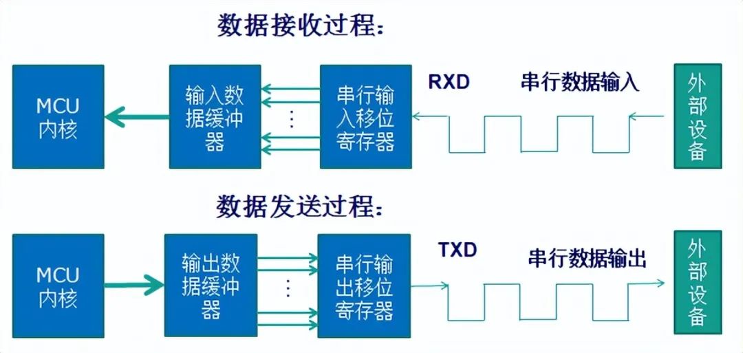
UART Parameters in STM32
The data packet for serial communication is transmitted from the sending device through its TXD interface to the receiving device’s RXD interface. The data packet format on both sides must be agreed upon to ensure normal sending and receiving of data.
Parameters to define for asynchronous communication in STM32 include: start bit, data bits (8 or 9 bits), parity bit (9th bit), stop bits (1, 1.5, or 2 bits), and baud rate settings.
The data packet for UART serial communication is structured in frames, with a commonly used frame structure being: 1 start bit + 8 data bits + 1 optional parity bit + 1 stop bit. As shown in the diagram below:
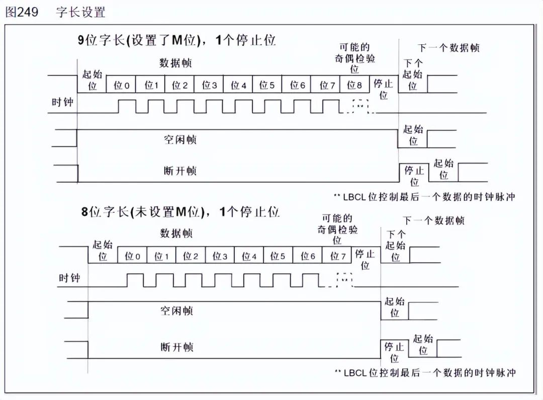
The parity bit can be either odd or even, which is a simple method for error checking. Odd parity means that the total number of 1s in the entire 9 bits (including data bits and parity bit) must be odd; even parity means that the total number of 1s must be even.
In addition to odd (odd) and even (even) parity, there can also be: 0 parity (space), 1 parity (mark), and no parity (noparity). 0/1 parity means that regardless of the content of the valid data, the parity bit is always 0 or 1.
UART (USART) Block Diagram
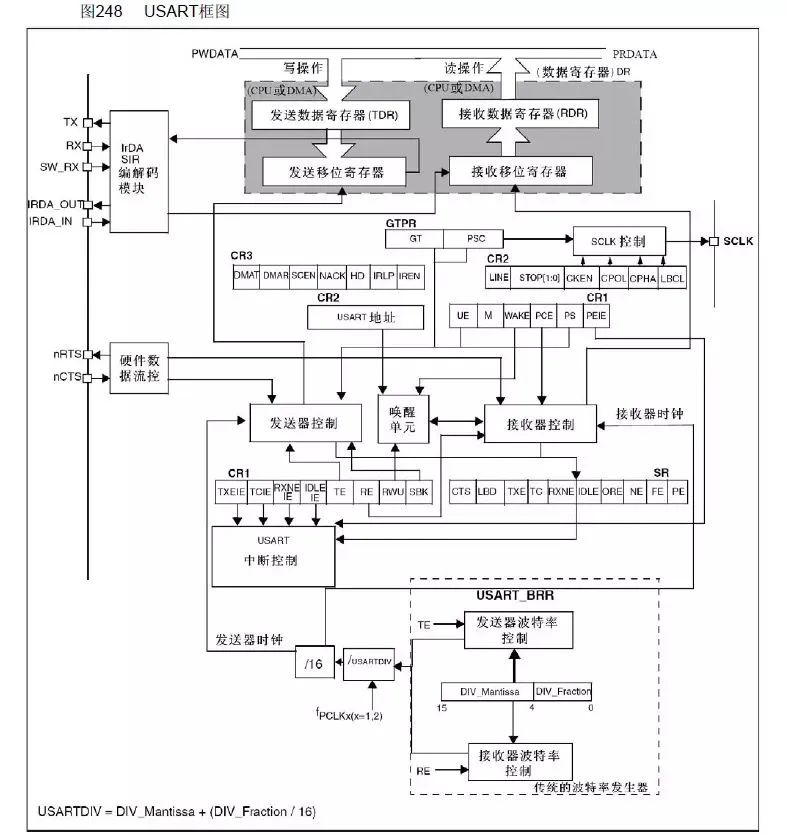
This block diagram is divided into three parts: upper, middle, and lower. This article briefly discusses the contents of each part; for specific details, please refer to the “STM32 Chinese Reference Manual”.
The upper part of the block diagram shows that data enters the receive shift register from RX, then enters the receive data register, and is ultimately read by the CPU or DMA; data from the CPU or DMA is sent to the transmit data register, then enters the transmit shift register, and is ultimately sent out through TX.
However, both sending and receiving in UART require baud rate control. How is baud rate controlled?
This brings us to the lower part of the block diagram, where there are arrows entering both the receive shift register and transmit shift register, connecting to the receiver control and transmitter control, respectively. This means that although asynchronous communication does not have clock synchronization signals, clock signals are provided internally within the serial port for control. The receiver clock and transmitter clock are controlled by what?
It can be seen that both the receiver clock and transmitter clock are connected to the same control unit, meaning they share a common baud rate generator. It is also visible how the receiver clock (generator clock) is calculated, as well as the calculation method for USRRTDIV.
END

Disclaimer: This article is a network reprint or adaptation, and the original author could not be found. Copyright belongs to the original author. If there are copyright issues, please contact.