I2C is a synchronous, half-duplex serial communication bus protocol used for connecting low-speed peripherals.
The main features include:
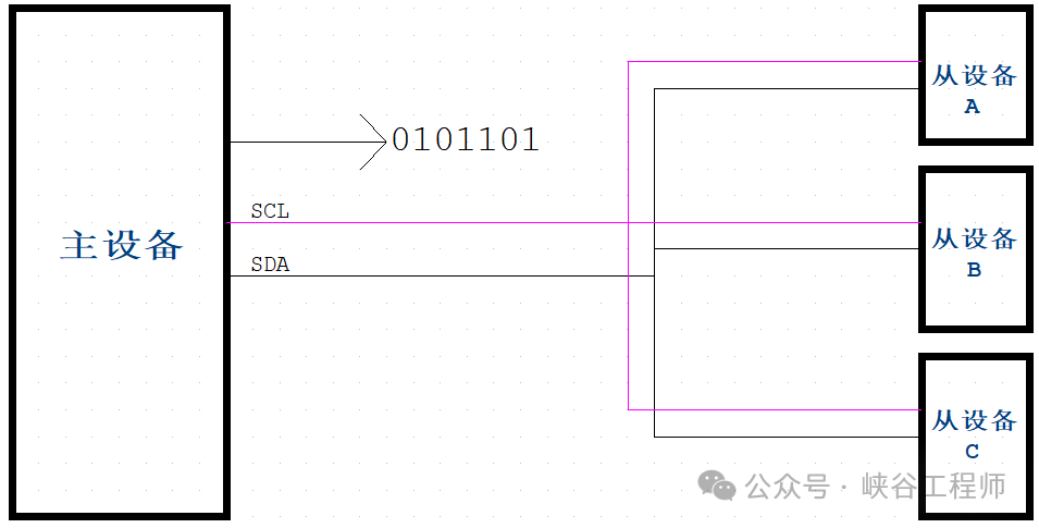
Two-wire system: SCL clock line and SDA data line
Multi-master and multi-slave: Supports multiple master and slave devices, but only one master is allowed at any given time.
Addressing: Each slave device has a unique address
Speed:
Standard mode: 100 kbps
Fast mode: 400 kbps
High-speed mode: 3.4 Mbps
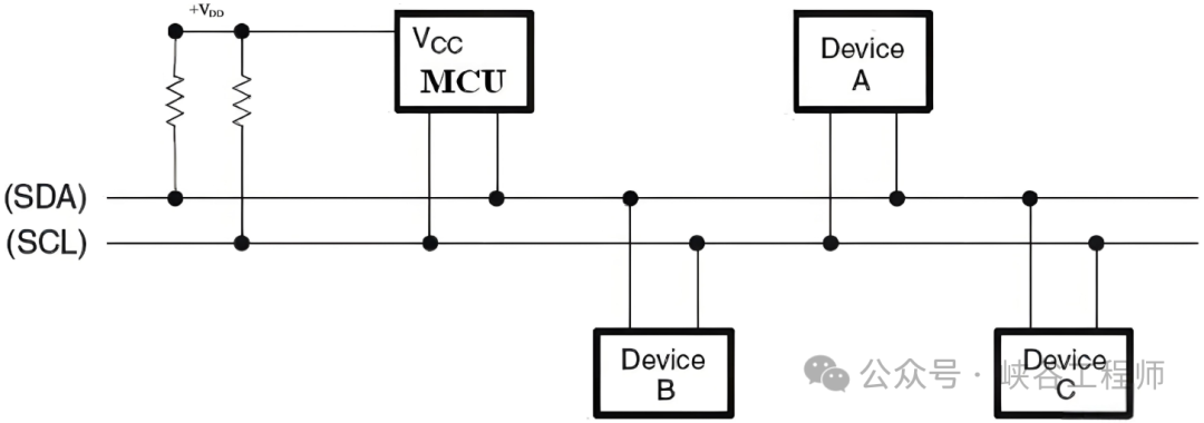
1. Physical Structure
1. Bus Structure
The I2C bus consists of two lines: the serial data line (SDA) and the serial clock line (SCL). Both lines are bidirectional, transmitting data and clock signals respectively.
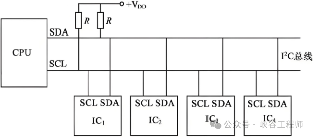
2. Electrical Characteristics
Voltage levels: In a standard I2C bus, the high level is typically the supply voltage, while the low level is close to 0V.
Pull-up resistors: Since the SDA and SCL lines are open-drain output structures, external pull-up resistors are required. The purpose of these pull-up resistors is to pull the bus high to the high-level state when the bus is idle.
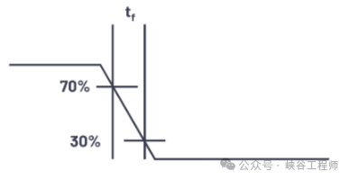
The selection of pull-up resistor values needs to consider factors such as bus load and operating speed. If the pull-up resistor is too large, it may cause the rise time on the bus to be too slow, affecting the accuracy of signal transmission. Conversely, if it is too small, it will increase the power consumption of the bus.
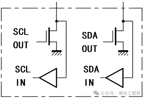
Driving capability: Each device connected to the I2C bus has a certain driving capability. Both master and slave devices can send and receive data via the SDA and SCL lines, but their driving capabilities collectively affect the number of slave devices that the bus can drive.
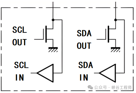
Noise tolerance: The I2C bus has a certain noise tolerance to ensure correct data transmission even in the presence of some noise interference. For example, during the high level, the bus voltage must drop to a certain level (below the high-level threshold) to be considered low level, and during the low level, the bus voltage must rise to a certain level (above the low-level threshold) to be considered high level.

2. Communication Structure
1. Master-slave architecture
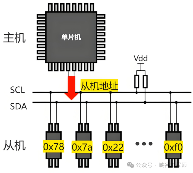
The I2C bus adopts a master-slave communication architecture. The master device is responsible for initiating communication, controlling the clock signal, and sending address and control information on the bus. The slave device is the device addressed by the master, performing data transmission or reception based on the commands sent by the master.
2. Address allocation
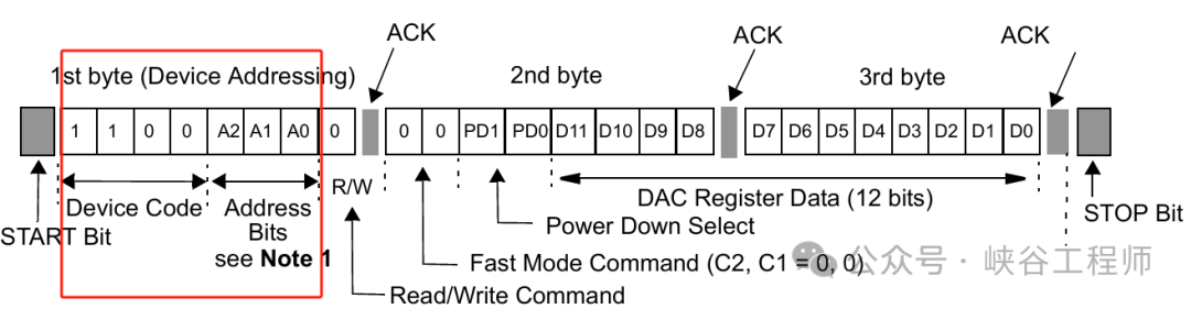
7-bit address: This is the most common address allocation method. Each slave device has a unique 7-bit address, and the master selects the slave device to communicate with by sending this 7-bit address. The 7-bit address also includes a read/write bit to indicate whether the master wants to read data from or write data to the slave device.
3. Data transmission unit
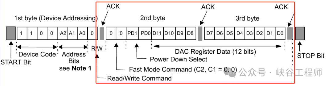
Data is transmitted on the I2C bus in bytes. Each byte contains 8 bits of data, followed by an acknowledgment bit (ACK/NACK). The acknowledgment bit is sent by the receiving device; if the receiving device successfully receives a byte of data, it sends an ACK (low level); if the reception fails or the receiving device is busy, it sends a NACK (high level).
3. Communication Timing
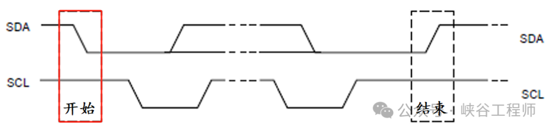
1. Start condition
The start condition is initiated by the master device. When the SCL line is high, the SDA line transitions from high to low, indicating the start of communication.
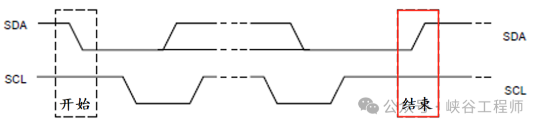
2. Stop condition
The stop condition is also initiated by the master device. When the SCL line is high, the SDA line transitions from low to high, indicating the end of this communication.
3. Data bit transmission
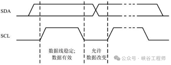
During data bit transmission, the SCL line generates clock pulses at the set clock frequency. For each data bit, the data is prepared on the SDA line, and when the rising edge of the SCL line arrives, the receiving device reads the data on the SDA line.

Each data bit has strict setup and hold time requirements to ensure correct data transmission.
4. Protocol
After the start signal, the address frame: After the master device sends the start signal, it immediately sends the 7-bit or 10-bit address frame of the slave device, along with a read/write bit.
Data frame transmission: If the master device wants to write data to the slave device, it sends the data frame after the address frame; if it wants to read data, the slave device sends the data frame after receiving the correct address frame. Data frames are also transmitted in bytes, with each byte followed by an acknowledgment bit.
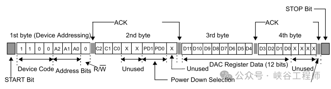
Acknowledgment mechanism: As mentioned earlier, the acknowledgment bit is sent by the receiving device to the sending device after each byte transmission to confirm whether the data was received successfully.
Repeated start signal: In some cases, the master device may need to send multiple commands or read multiple data blocks in a single communication process. In this case, a repeated start signal can be used. The repeated start signal is similar to the start signal, but it does not require a stop signal beforehand to initiate a new communication process without releasing the bus.

5. Operational Process
1. Master device initiates communication
The master device first checks if the bus is idle, meaning both SDA and SCL lines are in a high state. If the bus is idle, the master device sends the start condition to all connected slave devices, followed by the address frame and read/write bit of the slave device.
2. Slave device responds
After receiving the address frame sent by the master device, the slave device compares its own address with the received address. If they match and the read/write bit is correct, the slave device sends an ACK signal, indicating it can receive or send data.
3. Data transmission process
When the master device wants to write data to the slave device, it begins sending the data frame after receiving the ACK signal from the slave device. Each data frame is transmitted according to the specified protocol format, and the master waits for the slave’s ACK signal after each byte transmission. If the master device is reading data from the slave device, the slave starts sending data frames after receiving the correct address frame and read/write bit, and the master receives the data and sends an ACK signal after each byte, except for the last byte, where the master sends a NACK signal to indicate the end of data transmission.
4. Stop condition
After the data transmission is complete, the master device sends a stop condition to release the bus, allowing other devices to use the bus for communication.
When applying the I2C bus in practice, several issues need to be considered.
-
The selection of pull-up resistors should be determined based on the bus load capacitance and operating speed to ensure the bus can rise and fall properly.
-
Bus capacitance can also affect bus performance; excessive bus capacitance can slow down the rise and fall times of signals, which may require reducing the operating speed or increasing the value of pull-up resistors.
-
Clock synchronization and arbitration mechanisms are crucial in practical multi-master system applications to ensure compatibility of clock signals among master devices and to correctly arbitrate in case of contention.