🔍The program acquisition method is at the bottom of the article
📶The project includes complete programs, documentation, references, and operation videos
🌠Simulation Conclusion Preview
The testing effect using Vivado 2022.2 is as follows: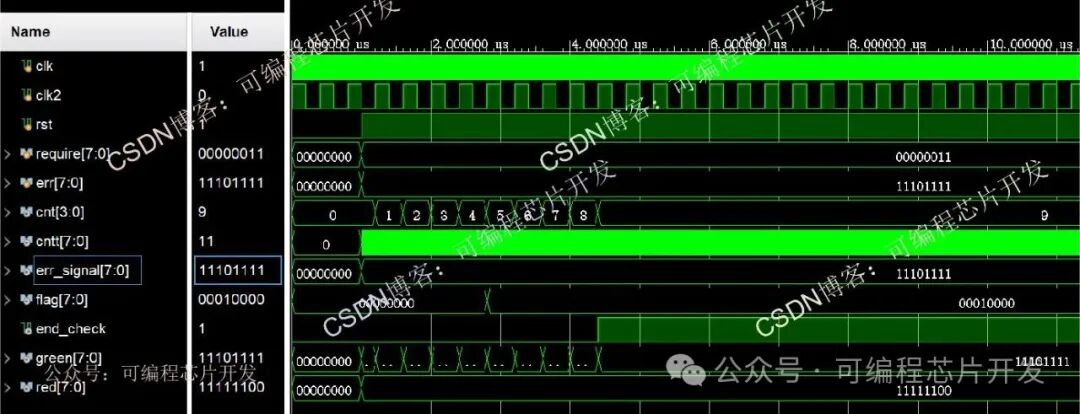
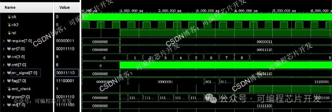 ⚡Program Function Description
<span><span>The function and principle of this program are as follows:</span></span>
System design requirements: Design an FPGA to control a digital clock that displays static and dynamic LED lights. The NBW-8 host can connect to 8 sub-units and has the following functions:
1. The host has LED display: The host uses a display screen to show the nursing level and system status. The host panel has 16/8 bi-color LED indicators that can display the working status of each sub-unit.
2. Continuous calling: The host can display calls from multiple sub-units and retain memory.
3. Secondary nursing: The nursing level can be designed on the host, with high-level and ordinary nursing levels.
4. Parallel function: The host has a parallel function, allowing multiple hosts to be connected to achieve multi-pole management.
5. Each sub-unit is connected to the door light.
After properly connecting the wires and ensuring correctness, turn on the host power. The host automatically enters the checking state for the sub-units, starting detection from unit 1: the sub-units display normally and flash briefly. If a certain sub-unit has a fault or is not connected, the corresponding route indicator light will turn green and remain on. After checking all 16/8 sub-units, the indicator lights that remain green will stay on for 5 seconds before turning off. After the check is complete, the host automatically returns to standby mode.
✨Partial Program
<span><span>The core content of the program is as follows</span></span>
1`timescale 1ns / 1ps//////////////////////////////////////////////////////////////////////////////////// Company: // Engineer: // // Create Date: 2025/08/30 19:09:47// Design Name: // Module Name: test// Project Name: // Target Devices: // Tool Versions: // Description: // // Dependencies: // // Revision:// Revision 0.01 - File Created// Additional Comments:// //////////////////////////////////////////////////////////////////////////////////

module test();reg clk;reg clk2;reg rst;reg[7:0]require;reg [7:0]err;
wire[3:0]cnt;wire[7:0]cntt;
wire[7:0]err_signal;wire[7:0]flag;
wire end_check;
wire[7:0]red;wire[7:0]green;
medical medicalu(              .clk        (clk),        //40M              .clk2       (clk2),       //1M              .rst        (rst),              .require    (require),              .err        (err),              .cnt        (cnt),              .cntt       (cntt),              .err_signal (err_signal),              .flag       (flag),              .end_check  (end_check),              .red        (red),              .green      (green)              );
initialbeginclk=1'b1;clk2=1'b1;rst=1'b0;require=8'd0;err=8'd0;#1000rst=1'b1;//require=8'b0000_0011;//err=8'b1110_1111;require=8'b0000_0011;err=8'b0001_1110;
end
always #5 clk=~clk;always #200 clk2=~clk2;

endmodule00X6_009m🌍Program Acquisition Method
Click the bottom left corner of WeChat to read the original text