1. LPC2103 Download (Programming) Methods
Programming the FLASH memory of LPC2103 can be achieved through the following three methods:
1) Using the built-in serial JTAG interface
2) Using In-System Programming (ISP) and UART
3) Using In-Application Programming (IAR) functionality
In this manual, we will mainly explain the two downloading methods: JTAG interface and ISP + UART.
Using the JTAG interface requires a corresponding emulator, while the ISP download method only requires a serial port.
Let’s first explain the ISP download method.
2. Hardware Connection
1) Connect the Chuangxue ARM7 core board to the Chuangxue multifunctional base board.
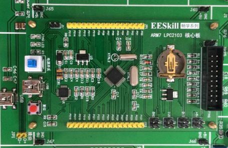
2) Insert one end of the USB cable (MINI) into the ARM7 core board USB interface, and connect the flat end (Type A) to the computer’s USB interface.
This completes the hardware connection between the Chuangxue ARM7 LPC2103 development board and the computer. The EESKILL Chuangxue ARM7 LPC2103 core board integrates USB to serial port functionality, allowing one USB cable to power the development board and enable virtual serial communication for program downloading.
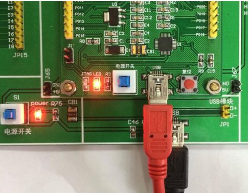
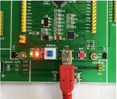
After connecting, check the ARM7 core board. After pressing the power switch, verify whether the power indicator lights up;
Check whether the power indicator lights up after pressing the power switch on the base board;
If everything is normal, you can proceed with the following operations.
3. Driver Installation
The Chuangxue ARM7 core board integrates the CP2102 chip, which can virtualize a USB interface on the computer as a serial port. This allows the ARM7 core board to be powered and programmed via a single USB cable, making it convenient to use the Chuangxue ARM7 core board on laptops or desktop computers without a serial port.
Before use, you need to install the CP2102 driver.
Open the driver program CP210x_VCP_Win_XP_S2K3_Vista_7.exe from the CD.
The path is: Driver – CP2102 Driver.
The following interface will appear.
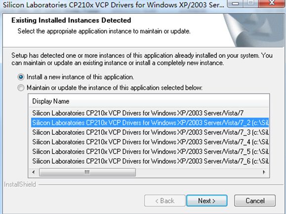
Click NEXT to enter the installation interface, as shown below
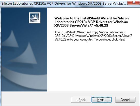
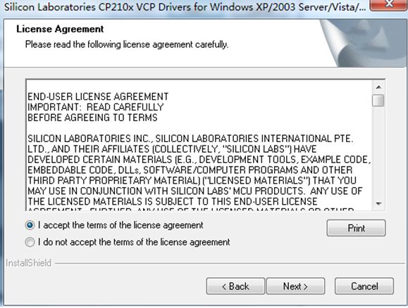
Click NEXT to enter the user agreement, select agree, and click Next
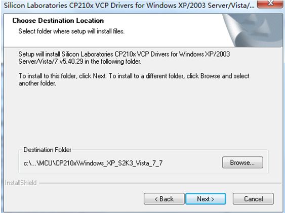
Select the installation path, choose the default path here, and click Next to continue
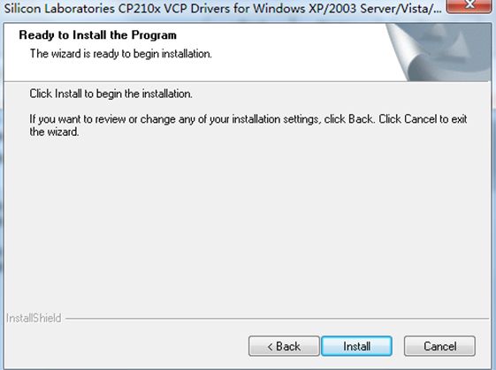
Click install to start the installation
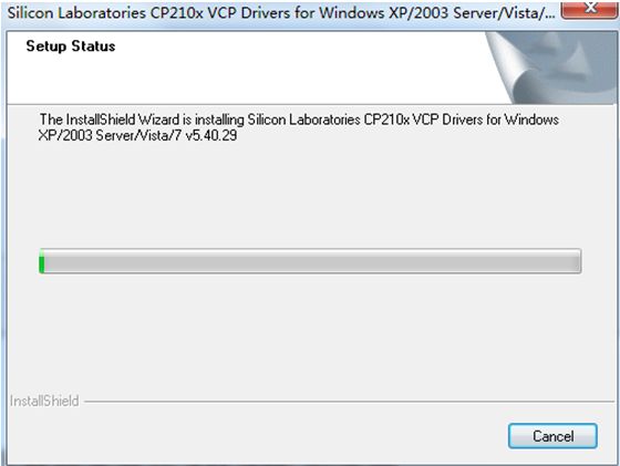
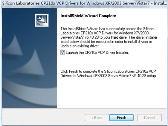
After the automatic loading is complete, the following dialog box will appear, click Finish
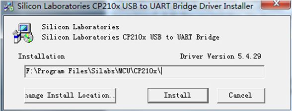
The following dialog box appears, click install, and the system will automatically install the CP2102 driver.
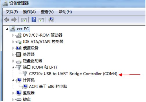
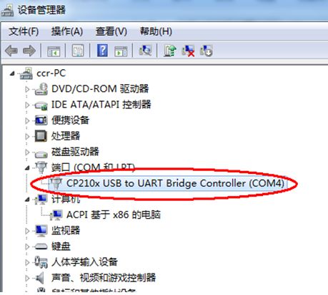
Reconnect the USB interface; note that you must turn on the power switch of the core board so that the computer can recognize the CP2102 module. If the driver installation is normal, a new USB to serial port will be found in the device manager.
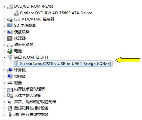
In the serial port with the CP210X label, the number in parentheses indicates the current virtual serial port number. This needs to be remembered as it will be needed when downloading the program to the ARM7 chip.
4. Install Download Software
Open the download software installation file Philips Flash Utility Installation from the CD, as shown below
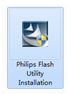
Double-click to open, and enter the installation interface
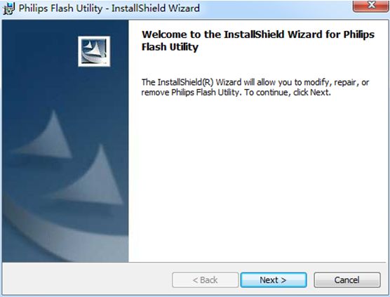
Click Next
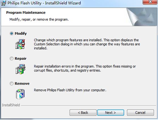
Continue to next
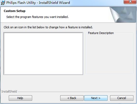
No settings required, continue to the next step
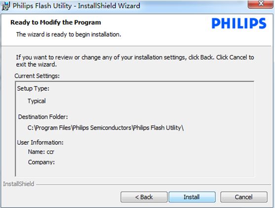
Click Install, and the software will install automatically
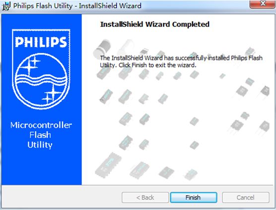
After the installation is complete, click Finish.
5. Software Settings
After installing the download software, we will open the software. In the Start menu – All Programs – Philips Semiconductors – Flash Utility folder, you can see the download software Launch LPC210X_ISP.exe
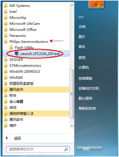
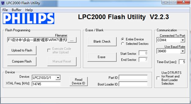
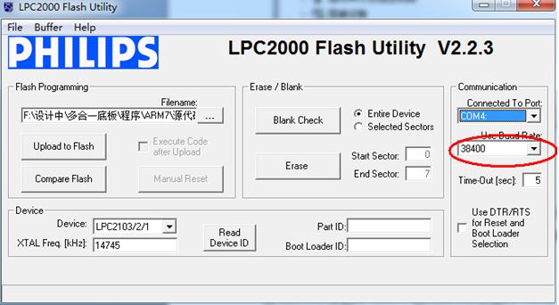
The software interface is as follows:
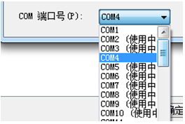
1) Select Port Number
The COM number here must match the port number of the CP2102 driver in the device manager
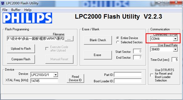
The port number displayed in my device manager is COM4; users can select based on their actual port value.
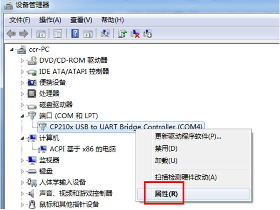
Friendly reminder: The LPC2000 Flash Utility download software supports a maximum port number of COM5. If the port number automatically assigned by the device manager exceeds 5, it can be manually modified as follows:
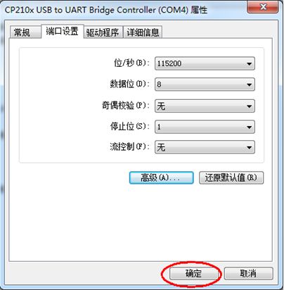
Right-click the CP2102 driver device, select Properties,
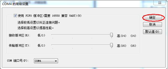
Open Port Settings – Select Advanced,
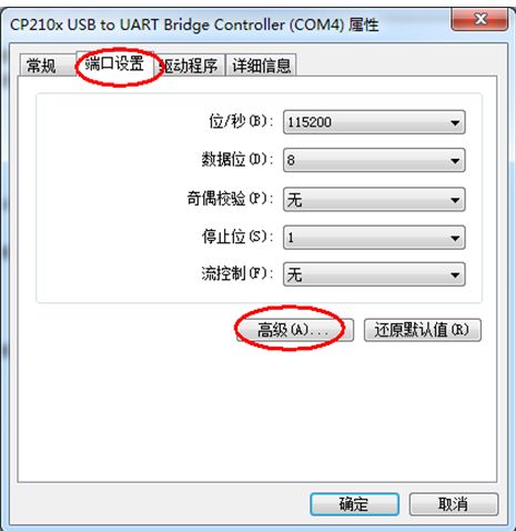
The interface will look like this:
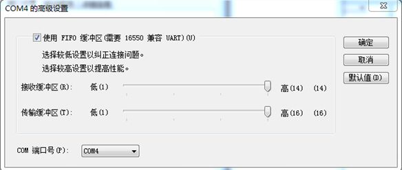
Modify the port number in the lower left corner, selecting any number within COM5:
After selecting, click Confirm
Then click Confirm to exit
Now the port number can be modified to within COM5, and you can reconnect the USB port to refresh the device.
For convenience in explanation, I will not make modifications here and will still use COM4.
2) Set Baud Rate
Set the baud rate to 38400
6. Read Chip ID
1) Short the J1 jumper on the core board
After reset, a low level at P0.14 is considered an external hardware request to start the ISP command processor. Therefore, two conditions are required for ISP downloading: the first is that the P0.14 pin should be low.
Let’s take a look at the circuit diagram of the Chuangxue ARM7 LPC2103 core board below
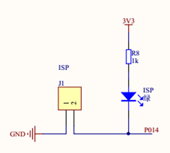
It can be seen that only when J1 is shorted will P0.14 be low. Therefore, short the J1 jumper on the core board, at this time, the ISP indicator light will be on.
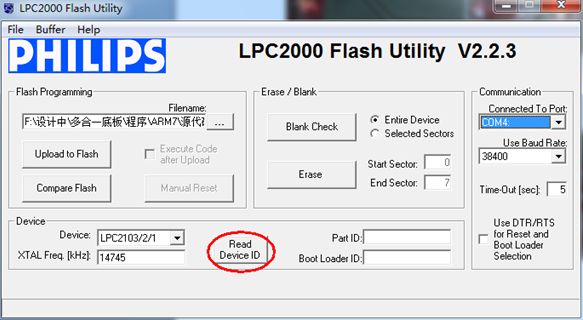
2) Click Read
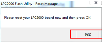
3) Prompt to Reset
The following prompt appears, indicating to reset the core board
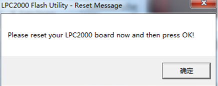
After this prompt appears, press the reset button on the core board, and then click OK
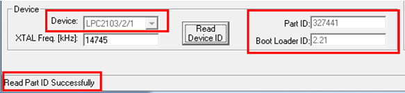
4) Successfully Read ID
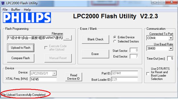
After successfully reading the chip ID, the download software will display the chip model and ID number, with the information prompt at the bottom:
Read Part ID Successfully, as shown below
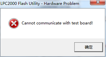
Common Errors:
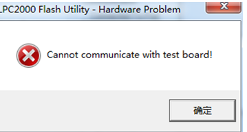
If the following error prompt appears, please click OK to close the error prompt, then press the reset button on the core board and try clicking the Read Device ID command again.
7. Program Download
After reading the chip ID, the chip is correctly connected to the download software, and at this point, you can proceed with program downloading.
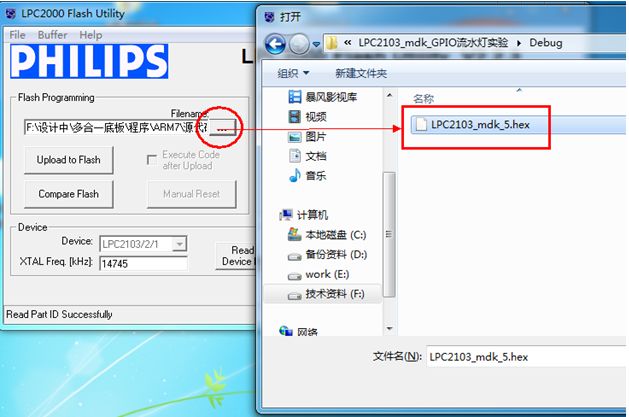
1) Load Program
Click the location below to load the HEX program you want to write to the ARM; the board CD provides matching test programs and experimental programs. Here we take the LED flashing HEX as an example.
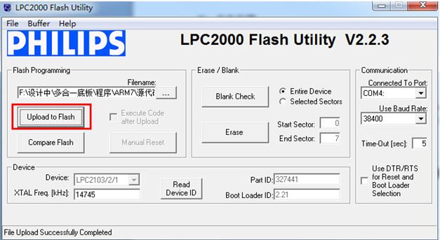
2) Click Download
Click Upload to Flash
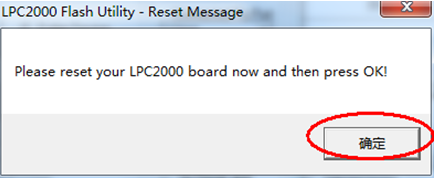
After the reset prompt appears, press the reset button on the core board, and then click OK
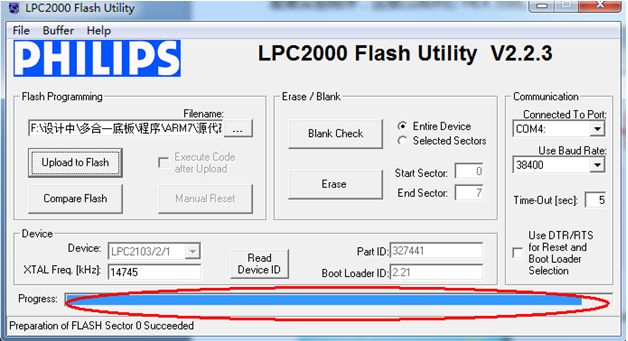
The program can be downloaded normally; during the download process, you can see the download progress bar:
After the download is successful, you will see the success message:
3) Run Program
After the program download is complete, disconnect the J1 jumper, press the reset button on the core board, and enter program run mode; the downloaded program will start running.
8. Common Problems and Solutions
After clicking download, if the following error prompt appears
a) First, please check if the J1 jumper has been shorted.
b) Check whether the core board is powered on
c) Check whether the core board is reset
d) If the above operations are fine, please press the reset button on the core board again, and click the download command once more.