Follow+Star PublicAccount to not miss exciting content
Direct Source | Renesas Embedded Encyclopedia
The biggest feature of using C language in embedded systems is the ability to directly manipulate registers, which is highly efficient.This article will discuss how to operate registers using C language in conjunction with the Renesas RA6M5 microcontroller.
1
Memory Mapping
Before discussing how to operate registers using C language, let’s first talk about memory mapping.
Registers, like RAM and FLASH, are also a type of storage device within the chip. Therefore, when we need to access them, we need to know their storage addresses.
1
Memory Mapping Table
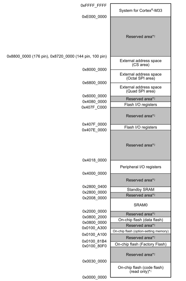
The following diagram shows the memory mapping table for the RA6M5. It can be seen that the internal memory of the RA6M5 chip is mapped to a whole block of 4G (0 ~0xFFFF FFFF) address space. We can also see that besides the address space regions for registers and SRAM, Flash, there are other types of address space regions, such as QSPI area and OSPI area. The Reserved area indicates the reserved region that has not yet been used.
2
Memory Region Division
Memory itself does not have address information; its address is assigned by the chip manufacturer or user. The process of assigning addresses to memory is called memory mapping. If a memory is assigned a new address, it is called memory remapping.
For the RA6M5 (176 pin) chip, its internal linear address space is divided into the following regions:
Table 2: Linear Address Space Region Division
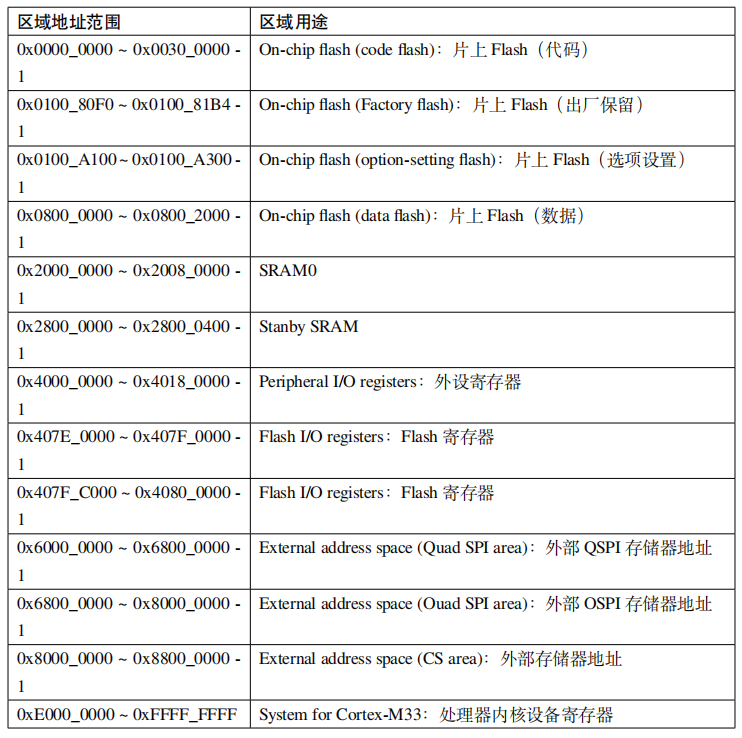
The “0x4000_0000~0x4018_0000-1” region in the table, which is “0x4000_0000~0x4017_FFFF”, maps to the registers of most peripheral modules.
3
Peripheral Base Address and Peripheral Register Address
The following diagram illustrates:
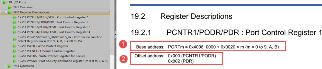
Point ① in the figure is the base address of the peripheral, which is the base address of the IO ports. Since the RA6M5 has not just one IO port but 16 ports (denoted as PORTm, where m=0~9,A,B), each port has a base address, which can be calculated using the formula shown in the figure.
Point ② in the figure is the address offset of the peripheral register, where the registers are PCNTR1/PODR/PDR, and “Offset address: 0x000” indicates the offset of this register relative to the base address.
For example
When we want to read the value of the PCNTR1/PODR/PDR register of PORT1, we first calculate the address of the register as: (0x40080000+0x0020*1), then convert this address to a C language pointer: (uint32_t*)(0x40080000+0x0020*1), and finally read the value: *((uint32_t*)(0x40080000+0x0020*1)).
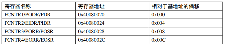
It is important to note that each peripheral module will have multiple registers, each with specific functions. For some relatively complex peripherals, the number of registers can reach dozens. For example, the base address of IOPORT1 is: 0x40080020, and the following table shows some of its register names, register addresses, and offsets relative to the base address.
Table 3: IOPORT1 Registers and Their Addresses
Note
Note: Due to different base addresses, the above table does not include registers like PmnPFS that are also related to IOPORT1.
4
Peripheral Registers
The following diagram shows the general format of peripheral registers.
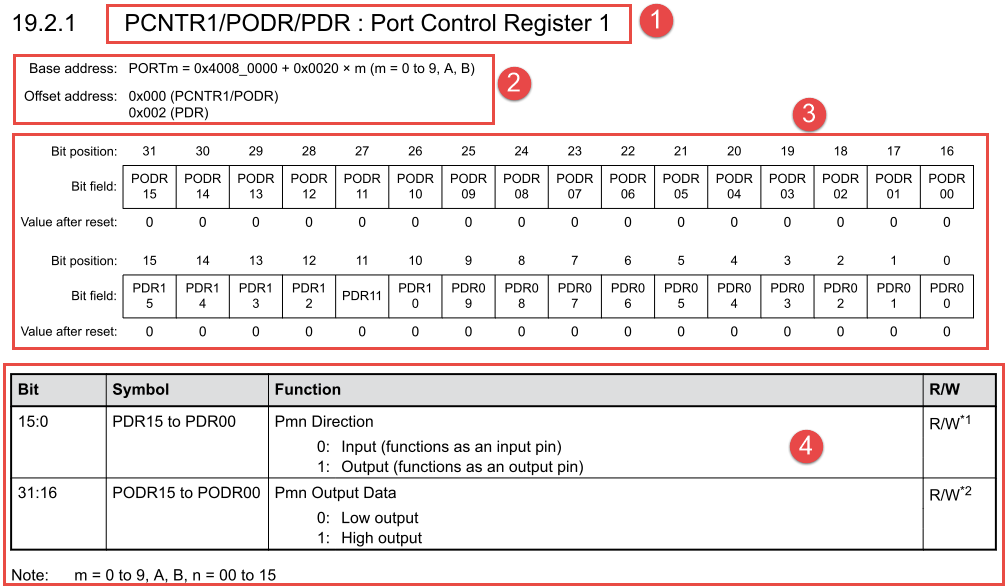
Description:
-
Register name.
-
Base address of the peripheral module and its register offset address.
-
Register bit table. The size of registers in a 32-bit MCU is generally 32 bits (bit), occupying four bytes. “Bit position” indicates the position of the bit in the register; “Bit field” indicates the function of different bit fields; “Value after reset” indicates the reset value of the bit.
-
Bit field function description. This part provides a detailed description of the function of each bit field.
2
How to Operate Registers Using C Language
1
Encapsulation of Registers in C Language
All the previous content about memory mapping is ultimately to help everyone better understand how to control the read and write of peripheral registers using C language, so this is the key content of this chapter.
1.1
Definition of Peripheral Module Base Address
For ease of understanding and memory in programming, we need to define the base addresses of peripheral modules with corresponding macros, where the base addresses are composed of their names as part of the macro name. The following are the macro definitions for the base addresses of IO ports.
List 1: Code Listing 3-1 Macro Definitions for IOPORT Peripheral Base Addresses
Swipe left and right to view the complete content
/* Peripheral Base Addresses */#define R_PORT0_BASE 0x40080000#define R_PORT1_BASE 0x40080020#define R_PORT2_BASE 0x40080040#define R_PORT3_BASE 0x40080060#define R_PORT4_BASE 0x40080080#define R_PORT5_BASE 0x400800A0#define R_PORT6_BASE 0x400800C0#define R_PORT7_BASE 0x400800E0#define R_PORT8_BASE 0x40080100#define R_PORT9_BASE 0x40080120#define R_PORT10_BASE 0x40080140#define R_PORT11_BASE 0x40080160#define R_PFS_BASE 0x40080800#define R_PMISC_BASE 0x40080D001.2
Definition of Register Structure
Since the number of registers is very large, if each register is accessed using a method like *((uint32_t*)(0x40080000+0x0020*1)), it would be cumbersome and troublesome. To facilitate access to registers, we will use the characteristics of C language structures to define registers and register bit fields, which is a common practice.
List 2: Code Listing 3-2 Using Structures to Encapsulate Peripheral Registers
Swipe left and right to view the complete content
// Note: Declaration of input/output ports/* C Language: IO definitions (access restrictions to peripheral registers) *///#define __I volatile const /*!< Defines 'read only'␣,→permissions *///#define __O volatile /*!< Defines 'write only'␣,→permissions *///#define __IO volatile /*!< Defines 'read / write'␣,→permissions *//* The following macros are used for structure members *//* following defines should be used for structure members *///#define __IM volatile const /*! Defines 'read only'␣,→structure member permissions *///#define __OM volatile /*! Defines 'write only'␣,→structure member permissions *///#define __IOM volatile /*! Defines 'read / write'␣,→structure member permissions *///typedef unsigned char uint8_t;//typedef unsigned short int uint16_t; /* Unsigned 16-bit integer variable *///typedef unsigned int uint32_t; /* Unsigned 32-bit integer variable *//*** @brief I/O Ports (R_PORT0)*/typedefstruct /*!< (@ 0x40040000) R_PORT0␣,→Structure */{union{union{__IOM uint32_t PCNTR1; /*!< (@ 0x00000000) Port Control␣,→Register 1 */struct{__IOM uint32_t PDR : 16; /*!< [15..0] Pmn Direction(Pin Pmn Direction)*/__IOM uint32_t PODR : 16; /*!< [31..16] Pmn Output Data(Pin Pmn Output Data)*/} PCNTR1_b;};/* ... Code too long to show ... */};union{union{__IM uint32_t PCNTR2; /*!< (@ 0x00000004) Port Control␣,→Register 2 */struct{__IM uint32_t PIDR : 16; /*!< [15..0] Pmn Input Data(Pin Pmn Input Data)*/__IM uint32_t EIDR : 16; /*!< [31..16] Pmn Event Input Data(Pin Pmn Event Input Data)*/} PCNTR2_b;};/* ... Code too long to show ... */};union{union{__OM uint32_t PCNTR3; /*!< (@ 0x00000008) Port Control␣,→Register 3 */struct{__OM uint32_t POSR : 16; /*!< [15..0] Pmn Output Set(Pin Pmn Output Set)*/__OM uint32_t PORR : 16; /*!< [31..16] Pmn Output Reset(Pin Pmn Output Reset)*/} PCNTR3_b;};/* ... Code too long to show ... */};union{union{__IOM uint32_t PCNTR4; /*!< (@ 0x0000000C) Port Control␣,→Register 4 */struct{__IOM uint32_t EOSR : 16; /*!< [15..0] Pmn Event Output Set(Pin Pmn Event Output Set)*/__IOM uint32_t EORR : 16; /*!< [31..16] Pmn Event Output Reset(Pin Pmn Event Output Reset)*/} PCNTR4_b;};/* ... Code too long to show ... */};} R_PORT0_Type; /*!< Size = 16 (0x10) */1.3
Definition of Peripheral Module Registers
In the previous step, we have defined the structure type R_PORT0_Type, which contains the register definitions for IOPORT. Next, we will use macro definitions to represent structure pointers, pointing to the base address of each port’s registers in the IOPORT peripheral.
List 3: Code Listing 3-3 Register Definitions
Swipe left and right to view the complete content
#define R_PORT0 ((R_PORT0_Type *) R_PORT0_BASE)#define R_PORT1 ((R_PORT0_Type *) R_PORT1_BASE)#define R_PORT2 ((R_PORT0_Type *) R_PORT2_BASE)#define R_PORT3 ((R_PORT0_Type *) R_PORT3_BASE)#define R_PORT4 ((R_PORT0_Type *) R_PORT4_BASE)#define R_PORT5 ((R_PORT0_Type *) R_PORT5_BASE)#define R_PORT6 ((R_PORT0_Type *) R_PORT6_BASE)#define R_PORT7 ((R_PORT0_Type *) R_PORT7_BASE)#define R_PORT8 ((R_PORT0_Type *) R_PORT8_BASE)#define R_PORT9 ((R_PORT0_Type *) R_PORT9_BASE)#define R_PORT10 ((R_PORT0_Type *) R_PORT10_BASE)Thus, we can use these macros to access each register of the various IO ports.
2
The Essence of Register Modification Operations: Read-Modify-Write
With the definitions of the IOPORT peripheral module registers above, we have completed the step of “Encapsulation of Registers in C Language”. Next, we can perform various operations on the registers using C language.
Operations on registers can either ignore the original value of the register and directly overwrite it with a new value; however, a more common operation is to modify based on the original register value, which means: first read the original value of the register, then modify that value, and finally write the new value back to the register to make it effective.
Next, we will introduce several common methods for modifying registers.
2.1
Clearing Certain Bits on the Register
Using the C language bitwise AND “&” operator can clear bits.
List 4: Code Listing 3-4 Bit Clearing: Bitwise AND &
Swipe left and right to view the complete content
// Clear certain bitsR_PORT0->PODR &= ~(1u<<0); // Clear bit 0 of PODR registerR_PORT0->PODR &= ~(1u<<6); // Clear bit 6 of PODR register// Clear multiple bitsR_PORT0->PODR &= ~(3u<<0); // Clear bits 0,1 of PODR registerR_PORT0->PODR &= ~(3u<<6); // Clear bits 6,7 of PODR register2.2
Setting Certain Bits on the Register
Using the C language bitwise OR “|” operator can set bits.
List 5: Code Listing 3-5 Setting Bits: Bitwise OR |
Swipe left and right to view the complete content
// Set certain bitsR_PORT0->PODR |= 1u<<0; // Set bit 0 of PODR registerR_PORT0->PODR |= 1u<<6; // Set bit 6 of PODR register// Set multiple bitsR_PORT0->PODR |= 3u<<0; // Set bits 0,1 of PODR registerR_PORT0->PODR |= 3u<<6; // Set bits 6,7 of PODR register2.3
Toggling Certain Bits on the Register
Using the C language bitwise XOR “^” operator can toggle bits.
List 6: Code Listing 3-6 Bit Toggling: Bitwise XOR ^
Swipe left and right to view the complete content
// Toggle certain bitsR_PORT0->PODR ^= 1u<<0; // Toggle bit 0 of PODR registerR_PORT0->PODR ^= 1u<<6; // Toggle bit 6 of PODR register// Toggle multiple bitsR_PORT0->PODR ^= 3u<<0; // Toggle bits 0,1 of PODR registerR_PORT0->PODR ^= 3u<<6; // Toggle bits 6,7 of PODR register
Cortex-M85 (RA8) Microcontroller: What is the Meaning and Function of TrustZone?
MCU Programming Software Sets Security Boundaries

Dual-Core Processor BOOT Startup Process