
01
Introduction
In the GJB 9001C quality management system requirements, clear requirements for general quality characteristics are proposed. Generally speaking, the general quality characteristics include reliability, maintainability, testability, supportability, safety, and environmental adaptability, collectively referred to as the “Six Characteristics”.
What specific projects does the implementation of general quality characteristics work include? What are the specific quantitative and qualitative indicators in the “Six Characteristics” work? How are the various indicators of the “Six Characteristics” verified? General quality characteristics represent a systematic, comprehensive, and specific work, and this article focuses on the preliminary discussion of the analysis and verification of the quantitative indicators of the “Six Characteristics”.
02
Overview
Military equipment generally has characteristics such as complex structures, numerous configurations, a large number of parts, and long design change cycles, which pose significant challenges to ensuring and improving the quality of military equipment products.
The quantitative and qualitative assessment of general quality characteristics of military equipment is very important for military equipment development enterprises and the military. The evaluation methods for general quality characteristics of equipment vary in focus; for example, GJB 9001C emphasizes evaluation from the perspective of the quality management system, while the product users focus on evaluation from the perspective of test operation quality. Regardless of the evaluation method, they all use the quantitative and qualitative indicators of general quality characteristics as references to determine whether requirements are met.
This article is based on the characteristics of military equipment, aiming to analyze and sort out the quantitative and qualitative indicators of reliability, maintainability, testability, supportability, safety, and environmental adaptability in general quality characteristics, propose corresponding quantitative indicators and qualitative requirements, clarify the applicable scope of quantitative indicators and the timing of verification, and ultimately form a research report on the analysis of quantitative requirements for general quality characteristics of military equipment and a project requirement analysis report.
03
Related Standards and Terminology for the “Six Characteristics” Work
3.1. Related Standards for the “Six Characteristics”
The following national military standards are related to reliability, maintainability, testability, supportability, safety, and environmental adaptability:
1) GJB 368 General Requirements for Equipment Maintainability Work
2) GJB 450 General Requirements for Equipment Reliability Work
3) GJB 451 Terminology for Reliability, Maintainability, and Supportability
4) GJB 900 General Requirements for Equipment Safety Work
5) GJB 1405A Terminology for Equipment Quality Management
6) GJB 1909 Requirements for Verification of Equipment Reliability, Maintainability, and Supportability
7) GJB 2547 General Requirements for Equipment Testability Work
8) GJB 3872 General Requirements for Comprehensive Support of Equipment
9) GJB 4279 General Requirements for Environmental Engineering of Equipment
3.2. Related Terminology for the “Six Characteristics”
🔺Reliability (2.32 reliability GJB 1405A) — The ability of a product to perform its specified functions under specified conditions and within a specified time.
🔺Maintainability (2.33 maintainability GJB 1405A) — The ability of a product to be maintained or restored to a specified state within a specified time and under specified conditions, following specified procedures and methods.
🔺Supportability (2.35 supportability GJB 1405A) — The ability of the design characteristics of the equipment and planned support resources to meet the requirements for peacetime readiness and wartime use.
🔺Testability (3.1 GJB 2547) — A design characteristic that allows a product to accurately determine its status (operational, non-operational, or performance degraded) in a timely manner and isolate internal faults.
🔺Safety (2.34 safety GJB 1405A) — The ability to avoid causing injury or harm to personnel, health, or the environment, and to prevent damage or loss to equipment or property.
🔺Environmental Adaptability (3.2 GJB 4239) — The ability of equipment (product) to achieve all its intended functions and performance under the effects of various environments it may encounter during its lifespan, and/or not to be damaged, is one of the important quality characteristics of equipment (product).
🔺Definition of Quality: The degree to which a set of inherent characteristics meets requirements.
04
Analysis and Verification of Quantitative Requirements for the “Six Characteristics”
4.1. Quantitative Indicators for Reliability
4.1.1. Indicator Name
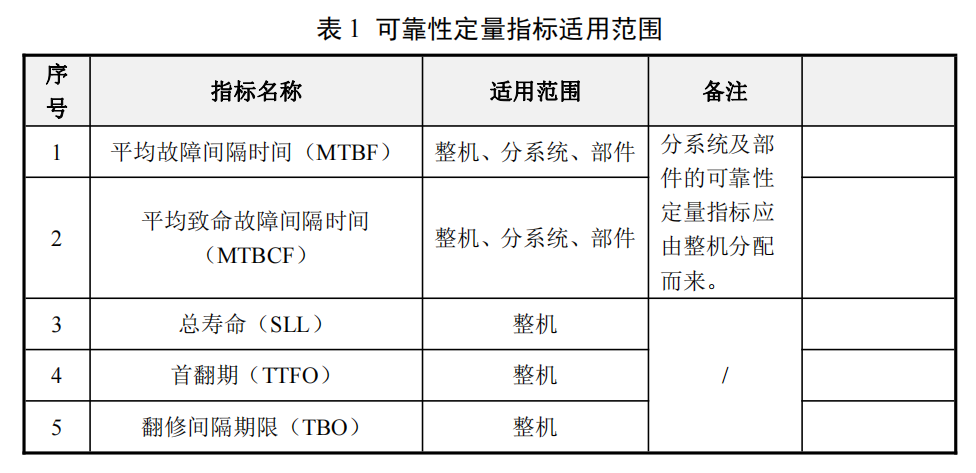
Based on the characteristics of different stages of development and use of equipment and the characteristics that users are concerned about, the important quantitative indicators for reliability are summarized as follows:
1) Mean Time Between Failures (MTBF): A basic reliability parameter for repairable products, defined as the ratio of the total number of life units of a product to the total number of failures within a specified time under specified conditions.
2) Mean Time Between Critical Failures (MTBCF): A reliability parameter related to tasks, defined as the ratio of the total task time of the product in a specified series of task profiles to the total number of critical failures.
3) Total Life (SLL): The total number of life units of a product from the start of use to decommissioning under specified conditions.
4) Time to First Overhaul (TTFO): The total number of life units of a product from the start of use to the first major overhaul under specified conditions.
5) Overhaul Interval (TBO): The ratio of the total number of life units of a product from the start of use to decommissioning to the number of overhauls under specified conditions.
4.1.2. Applicable Scope
The applicable scope of reliability quantitative indicators is shown in Table 1 below.
4.1.3. Verification Stages and Methods
The reliability quantitative indicators of military equipment should be assessed using a combination of reliability predictions, internal trials, and external trials or verifications. According to international practice, the assessment of reliability indicators only considers their minimum acceptable values.
a) Reliability Prediction
During the scheme and detailed design stages of military equipment, the MTBF values of the whole machine, subsystems, and components can be predicted based on GJB/Z 299C-2006 “Reliability Prediction Manual for Electronic Equipment” to evaluate whether the design at the current stage meets the quantitative requirements of reliability indicators and to identify weak links in reliability in the design for necessary improvements.
b) External Verification
Based on past experience, the reliability indicators of the whole military equipment, core components, functional systems, and equipment that cannot be tested in-house due to conditions should generally use the “external verification” method as specified in relevant standards, which should be completed within 2 to 4 years after design finalization and troop trials (specific timing can be specified in the model’s “Verification Outline”). The main principles of external verification are as follows:
1) Verification should be conducted under the real use environment and support conditions of the troops in conjunction with troop trials;
2) Before verification, the user and the developer should jointly formulate a detailed verification outline or plan;
3) A verification organization should be established, including a leadership group and a verification working group, where the leadership group is responsible for overseeing the reliability external verification process, and the verification working group is responsible for organizing and implementing the reliability external verification;
4) Verification should use military equipment that has been type approved and has undergone a certain period of use, effectively eliminating early failures, and the sample size, cumulative operating time, and individual machine cumulative operating time should all be regulated accordingly.
c) Reliability Acceptance Testing
The testing before the delivery of military equipment is both a product adjustment test by the supplier and a product acceptance test by the buyer. Although the adjustment test can preliminarily check the overall reliability status of military equipment, it cannot achieve the confidence level satisfactory to the buyer. Therefore, the buyer may conduct reliability acceptance tests on important equipment in mass production when conditions for testing are met.
d) Life and Overhaul Period Verification
Considering that military equipment can generally be replaced, the service life of military equipment typically refers to the structural life of the body, which has two main indicators: one focusing on fatigue life under actual load conditions and the other focusing on material life under corrosive environmental conditions. Currently, the method for determining the total life of the whole machine is mainly empirical. In China, it is primarily determined based on statistics of natural elimination of military equipment and the practical experience of some equipment and overhauls. For electronic equipment, accelerated life testing can be used to determine component life, thereby assessing the replacement cycle of components.
4.2. Quantitative Indicators for Maintainability
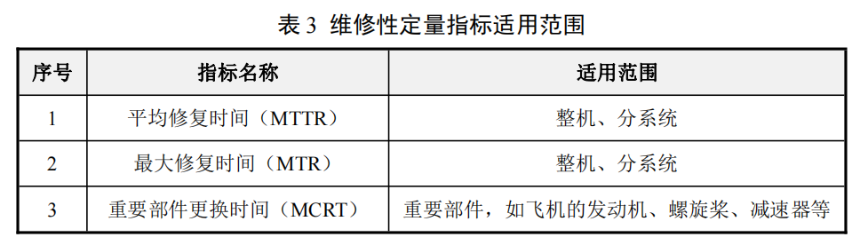
4.2.1. Indicator Name
Based on the characteristics of military equipment development and use stages and the characteristics that users are concerned about, the quantitative indicators for maintainability are summarized as follows:
1) Mean Time To Repair (MTTR): A basic parameter for maintainability, defined as the ratio of the total repair time for products at a specified maintenance level to the total number of failures at that level within a specified time and under specified conditions.
2) Maximum Repair Time (MTR): The repair time required to reach the specified level of maintenance.
3) Major Component Replacement Time (MCRT): The time required under specified conditions to approach, disassemble, and inspect major components (such as engines, propellers, gearboxes, etc.) and bring them to a usable state.
4.2.2. Applicable Scope
The applicable scope of maintainability quantitative indicators is shown in Table 3 below.
4.2.3. Verification Stages and Methods
The maintainability indicators of military equipment, core components, functional systems, and electronic equipment should generally use the “external verification” method as specified in relevant standards for assessment, which should generally be completed within 2 to 4 years after design finalization and troop trials (specific timing can be specified in the model’s “Verification Outline”). The principles of external verification should be the same as those for reliability verification.
a) Maintainability Prediction
During the scheme and detailed design stages of military equipment, the MTTR values of the whole machine, subsystems, and components can be predicted based on GJB/Z 57-94 “Maintainability Allocation and Prediction Manual” to evaluate whether the design at the current stage meets the quantitative requirements of maintainability indicators and to identify weak links in maintainability in the design for necessary improvements.
b) MTTR Verification (Grassroots Level)
The sample size for MTTR verification of system-level equipment should be statistically determined based on the actual number of failures, but generally should not be less than 50 times. If the number of failures recorded is too small, consider appropriately setting up simulated failures. If a fixed sample size is prescribed for maintainability verification, the sample size for maintenance work on external replaceable units should be determined using a proportional stratified sampling method, as shown in the model below:
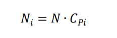
Where:
Ni — The sample size for maintenance work on the i-th external replaceable unit;
N — The sample size for maintenance work on the system or equipment;
CPi — The failure allocation rate for the i-th external replaceable unit, determined by the following formula
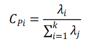
Where:
λi — The failure rate for the i-th external replaceable unit, 1/h;
k — The total number of replaceable units in the system or equipment.
c) Whole Machine Maintainability Verification (Grassroots Level)
The maintainability verification of the whole military equipment should generally be conducted synchronously with the reliability external verification of the whole machine. Generally speaking, statistically recording the natural failures and maintenance work time during the reliability external verification period can basically meet the sample size requirements for maintenance work on the whole machine.
4.3. Quantitative Indicators for Testability
4.3.1. Indicator Name
Based on the characteristics of military equipment development and use stages and the characteristics that users are concerned about, the quantitative indicators for testability are summarized as follows:
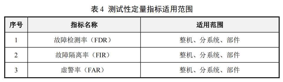
1) Fault Detection Rate (FDR): The ratio of the number of faults correctly detected using specified methods to the total number of faults, expressed as a percentage.
2) Fault Isolation Rate (FIR): The ratio of the number of detected faults correctly isolated to not greater than the specified ambiguity to the number of detected faults, expressed as a percentage.
3) False Alarm Rate (FAR): The ratio of the number of false alarms occurring within a specified period to the total number of fault indications within the same period, expressed as a percentage.
4.3.2. Applicable Scope
The applicable scope of testability quantitative indicators is shown in Table 4 below.
4.3.3. Verification Stages and Methods
Based on the characteristics and complexity of military equipment, the types and timing of testability verification vary for products at different levels. Testability verification includes testability demonstration and testability evaluation.
Testability Demonstration is conducted during design finalization or production finalization, or during testing, to determine whether the product meets the specified testability requirements. Testability demonstration should be conducted in a test environment that simulates actual use as much as possible. It is generally led by the contractor, with the buyer reviewing the demonstration plan and participating in the demonstration process. For system-level and whole machine testability requirements, external verification should be conducted using prototypes during the testing process; for equipment or LRU-level testability requirements, verification should be conducted at the field level, where faults are injected into the tested unit under simulated actual use conditions.
Testability Evaluation is conducted during the usage phase to statistically analyze field data to evaluate whether the product’s testability meets the specified target value requirements. This work is completed by the buyer, evaluating the testability requirements at the field maintenance level. The false alarm rate of BIT is usually evaluated after the product is put into external use.
Since testability is closely related to maintainability, reliability, and performance, testability verification can be combined with maintainability verification, reliability testing, and performance testing to obtain data useful for testability assessment, avoiding unnecessary duplication of work, especially as it is usually combined with maintainability verification. However, this combination is generally only on certain projects and cannot replace testability verification tests. To conduct testability verification, it is necessary to develop a testability verification plan, specify verification requirements, and analyze and evaluate testability test data.
a) Verification of Fault Detection Rate and Fault Isolation Rate
This section introduces a commonly used testability verification method—the list method. It verifies by injecting faults, usually used to verify the fault detection rate rFD and fault isolation rate rFI of airborne systems or equipment.
Fault injection can be achieved by introducing faulty components, or by opening leads, short-circuiting components, or misaligning the tested unit. The selection and allocation of simulated fault samples can be implemented according to Appendix B of GJB 2072-94 or A10.4, A10.5 of the American military standard MIL-STD-471A. Each simulated fault should be analyzed to determine whether it accurately reflects the product’s faults. Additionally, each simulated fault should be analyzed to determine the ambiguity of the product’s BIT, external testing equipment, or manual testing for fault isolation at the field level, as well as the ambiguity for fault isolation at the combat and support levels, and the results of these analyses should be filled in the product testability verification and evaluation table, as shown in Table 5.
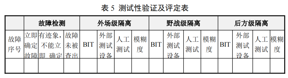
Based on the information listed in Table 5, the fault detection rate rFD and the observed values of BIT, external testing equipment, and manual testing fault isolation rates (rFI) at the field, combat, and support levels can be calculated to verify whether these testability parameter values meet the specified requirements. The formula for calculating the fault detection rate is:
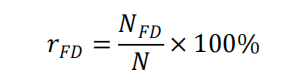
Where:
rFD — Fault detection rate;
NFD — Number of detected faults;
N — Total number of simulated faults. The formula for calculating the fault isolation rate is:
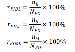
Where:
rFIBL — BIT fault isolation rate (ambiguity ≤ L);
rFIEL — External testing equipment fault isolation rate (ambiguity ≤ L);
rFIML — Manual testing fault isolation rate (ambiguity ≤ L);
nB — Number of faults isolated by BIT;
nM — Number of faults isolated by manual testing;
NFD — Number of detected faults, equal to the sum of NB, NE, and NM.
b) Verification of False Alarm Rate
Due to the numerous factors affecting the false alarm rate, the false alarm rate in external use is much higher than the test verification value. Therefore, the verification of the false alarm rate is generally conducted during the external testing period or after the equipment is put into service. Additionally, data from reliability tests and performance tests can be utilized to verify the false alarm rate.
The following is an approximate verification method. It is based on the definition of the false alarm rate as the average number of false alarms per 24 working hours.
1) Determine the cumulative working time T of the equipment during the verification test, which includes the time for performance testing and reliability testing. If the verification test is required to end before the completion of the use test, the false alarm rate verification should end when the contractor’s reliability test is completed.
2) Calculate the expected number of false alarms NF:
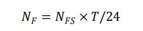
Where: NFS — Average expected number of false alarms (calculated based on the average working hours of the equipment per 24 hours);
T — Cumulative working time of the tested unit.
3) Use the following formula to verify whether the specified requirements are met:
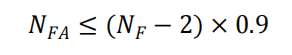
Where: NFA — Observed number of false alarms obtained during the test.
4.4. Quantitative Indicators for Supportability
4.4.1. Indicator Name
Based on the characteristics of military equipment development and use stages and the characteristics that users are concerned about, the quantitative indicators for supportability are summarized as follows:
1) Operational Availability (AO): An availability parameter related to working time and non-working time, defined as the ratio of the product’s working time to the sum of working time and non-working time.
2) Inherent Availability (A1): An availability parameter related only to working time and repair time, defined as the ratio of the average time between failures to the sum of the average time between failures and average repair time.
3) Pre-mission Preparation Time (STTM): The preparation time required for the equipment to enter mission status, usually including the time for unsealing and maintenance of combat-ready equipment. It is a component of support time.
4) Equipment Readiness Rate (MRR): The ratio of the number of equipment that can perform tasks at any time to the actual number of equipment, usually expressed as a percentage. It is mainly used to measure the technical status and management level of equipment, as well as the degree of support that equipment can provide for combat, training, and duty.
5) Mission Capability Rate (MCR): The ratio of the time that equipment can perform at least one specified task within a specified period to the total time under the control of combat troops. It is the sum of the rates for performing all tasks and performing partial tasks.
6) Utilization Rate (UR): The average number of life units used or the average number of tasks performed by the equipment within a specified calendar period, such as the sortie rate of aircraft.
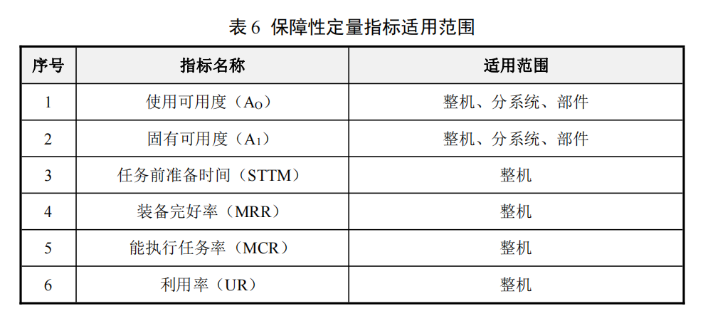
4.4.2. Applicable Scope
The applicable scope of supportability quantitative indicators is shown in Table 6 below.
4.4.3. Verification Stages and Methods
a) Verification Stages
Supportability testing and evaluation run throughout the entire lifespan of the model, with different focuses and goals at different stages. The overall goal of supportability testing and evaluation is:
1) To provide assurance of the supportability of the equipment system under expected wartime conditions;
2) To check whether the developed system has the capability to reach the established system readiness level;
3) To check whether the system readiness targets can be achieved during the usage period under both peacetime and wartime utilization rates.
To make full use of limited resources, the comprehensive support considerations should be fully integrated into the overall testing and evaluation outline of the product, utilizing the results of other testing work to achieve the above goals.
Testing and evaluation are divided into two main types: development testing and evaluation, and usage testing and evaluation.
Table 7 provides the comprehensive support goals for products during various stages of development testing and evaluation, and usage testing and evaluation.
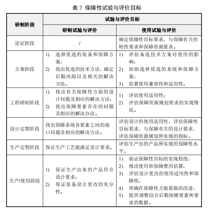
As can be seen from the table, development testing and evaluation mainly consist of engineering tests, utilizing the results of these engineering tests to identify problems and find solutions through design means, thereby improving the supportability of the equipment and the effectiveness of the support system, ensuring that the equipment and its support system can match each other.
Development testing and evaluation work is primarily conducted in simulated environments, with most of the work completed by the contractor.
Usage testing and evaluation primarily consist of statistical tests, utilizing these statistical tests to evaluate the level of supportability achieved by the equipment, assess the effectiveness of the support system, identify gaps between the supportability level and requirements, or verify that the equipment system has met the specified readiness and supportability requirements.
Usage testing and evaluation work is usually conducted by a third party independent of the buyer and the contractor, generally in an external real environment.
b) Testing Methods
The appropriate testing method should be chosen based on different purposes:
1) When only principles or test-type prototypes are available, the main goal is to evaluate the correctness of the principles and identify various design defects to find corrective measures, laboratory testing should be adopted;
2) When evaluating the level of supportability of the equipment and the effectiveness of the support system, testing should be conducted in an external environment.
c) Evaluation Methods
The appropriate evaluation method should be chosen based on different purposes, with evaluations divided into qualitative and quantitative evaluations.
When the main purpose is to identify design defects, qualitative evaluation methods should generally be used; identifying the defects present in the design and conducting a thorough analysis of the causes of these defects to find methods to eliminate them.
When the main purpose is to evaluate the level of supportability of the equipment and the effectiveness of the support system, quantitative evaluation methods should be used to indicate the existing level of supportability of the equipment and the effectiveness of the support system, identifying whether the specified requirements have been met and the gaps between requirements.
4.5. Quantitative Indicators for Safety
4.5.1. Indicator Name
Based on the characteristics of military equipment development and use stages and the characteristics that users are concerned about, the quantitative indicators for safety are summarized as follows:
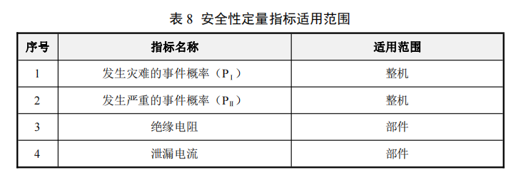
1) Probability of Catastrophic Events (PⅠ): The probability of military equipment experiencing catastrophic failures leading to crashes or in-flight disintegration, generally required to be < 1×10⁻⁹.
2) Probability of Serious Events (PⅡ): The probability of military equipment experiencing serious failures leading to significant damage (e.g., engine failure) that may result in crashes, generally required to be < 1×10⁻⁷.
3) Insulation Resistance: The direct current resistance of insulation under specified conditions, which is the most basic insulation indicator for electrical equipment and electrical lines, generally required to be > 500MΩ.
4) Leakage Current: The current flowing into the ground or external conductive parts of the circuit under non-fault conditions, generally required to be < 2mA.
4.5.2. Applicable Scope
The applicable scope of safety quantitative indicators is shown in Table 8 below.
4.5.3. Verification Stages and Methods
Military equipment requires relevant verification work to be conducted during the demonstration stage, scheme stage, engineering development stage, production finalization stage, and usage stage. The main tasks are as follows:
1) During the demonstration stage, based on the experience of similar products and considering the characteristics of the newly developed product, verify and assess safety requirements to ensure the correctness and completeness of safety requirements, and that they are technically verifiable. The verification will determine which safety requirements may need to be abandoned during the product lifecycle and ultimately establish the safety verification requirements, forming a safety verification requirements document;
2) During the scheme stage, the main safety verification work is to review and verify the safety work plan, participate in the design of military equipment schemes, key technical breakthroughs, and the trial production and testing of new components and subsystems, and conduct safety testing and verification in conjunction with the development of model prototypes or principle prototypes, determining whether safety requirements are reasonable, ensuring that key safety technologies have been resolved, and that the safety work plan is practical;
3) During the engineering development stage, the main safety verification work is to first review the safety work plan. If a product has multiple contractors, there should usually be a comprehensive safety work plan to coordinate the safety work of all contractors and the main contractor. Secondly, conduct safety reviews of the design to ensure that safety requirements have been met and that previously identified hazards have been eliminated or controlled; then review all tests to ensure that no new hazards are introduced; finally, document the safety verification work conducted during this phase;
4) In the production finalization stage, the main purpose of safety verification work is to verify whether products meeting safety requirements have been produced according to approved specifications and design documents. During this stage, safety controls and inspections of the production process must be conducted, and the impact of various engineering proposals on safety should be reviewed;
5) During the usage stage, the main safety verification work to be done by the user is to conduct regular safety reviews to determine the scope of identified issues (whether they exist in all active systems) and their frequency; simultaneously monitor the system to determine whether the design, usage, maintenance, and emergency procedures are appropriate.
a) Component Safety Verification
Component safety testing should be conducted during the component design stage or conducted by the component supplier, who should submit relevant test reports. Component safety testing items include, but are not limited to, insulation resistance, leakage current, dielectric strength, over-voltage and under-voltage protection, etc. The methods for component safety testing should refer to the design specifications or standards of related products, such as the requirements specified in GJB 181B-2012 “Aircraft Power Supply Characteristics” for electrical equipment in aircraft.
b) Whole Machine Safety Verification
For specific loss events or the probability of consequences from accidents, quantitative requirements are proposed to clarify and implement safety quantitative requirements in engineering. This usually requires establishing an engineering model according to certain rules, namely a probabilistic safety model. Verification activities for such safety objectives can typically utilize probabilistic risk assessment (PRA) or fault tree analysis (FTA) methods.
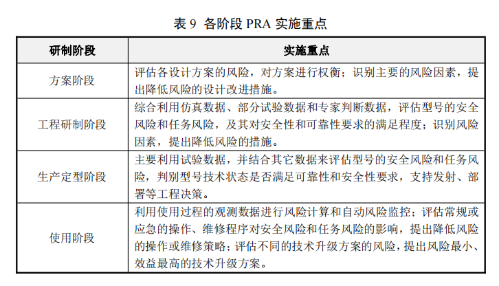
Probabilistic Risk Assessment (PRA) is one of the most representative quantitative safety evaluation methods. It is a structured, integrated logical analysis method for identifying and assessing risks in complex systems, using event trees, fault trees, and other methods to construct risk event chain models, integrating various qualitative and quantitative information (such as test data, field data, expert judgment, etc.) for model quantification and uncertainty analysis, thereby rationally predicting the risk level of the system, analyzing key factors affecting risk, and providing decision support for risk management throughout the lifecycle of complex systems. PRA is mainly applicable to large complex systems, such as aircraft. PRA can be conducted at different stages of development, with different focuses at different stages. The focus of PRA implementation during different stages of development and usage is shown in Table 9.
Fault Tree Analysis (FTA) takes an undesirable fault event (or catastrophic hazard) as the analysis target, using a top-down, hierarchical fault cause logic analysis to identify necessary and sufficient direct causes of the fault event layer by layer, ultimately identifying all causes and combinations of causes that lead to the occurrence of the top event.
When basic data is available, the probability of the top event and the quantitative indicators of bottom event importance can be calculated. When conducting quantitative safety assessments using FTA, the inverse event of the safety probability indicator requirements is treated as the top event for fault tree modeling, decomposing layer by layer, and obtaining fault data for hierarchical products to quantitatively assess whether the safety probability indicator requirements are met. The basic steps of FTA are shown in Figure 1.
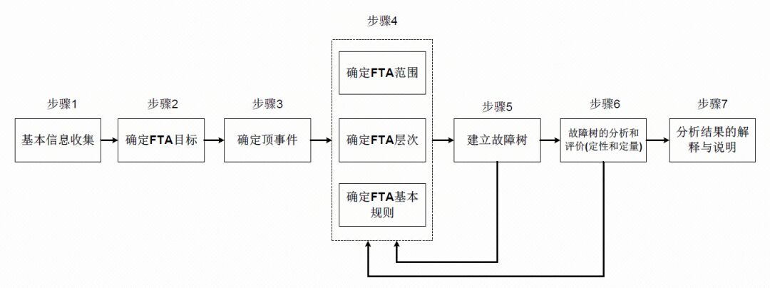
Figure 1 Basic Steps of FTA
4.6. Quantitative Indicators for Environmental Adaptability
4.6.1. Indicator Name
Based on the characteristics of military equipment development and use stages and the characteristics that users are concerned about, common quantitative indicators for environmental adaptability are summarized as follows:
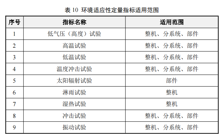
1) Low pressure (altitude) test;
2) High-temperature test;
3) Low-temperature test;
4) Temperature shock test;
5) Solar radiation test;
6) Rain test;
7) Humidity test;
8) Shock test;
9) Vibration test;
4.6.2. Applicable Scope
The applicable scope of environmental adaptability quantitative indicators is shown in Table 10 below.
4.6.3. Verification Stages and Methods
a) Engineering Development Stage
During the engineering development stage of military equipment, extensive development tests are required to verify the effectiveness of design measures, including environmental baseline tests and reliability strengthening tests.
Environmental baseline tests may need to be repeated, and are routine tests at this stage. Routine tests are preventive tests that can identify potential performance or quality issues during the process, allowing for corrective actions. The reports or records of routine tests also serve as important traceable information for product development, manufacturing, and delivery management. Routine tests typically focus on the most critical and essential indicators, not necessarily verifying all items required by combat technical indicators. Environmental baseline tests generally target components, aiming to identify weaknesses in environmental adaptability in the design as early as possible and take corrective measures to enhance component reliability.
b) Production Finalization Stage
During the military equipment identification stage, environmental identification tests must be conducted. Identification tests should be completed with the participation of user unit representatives to verify whether the environmental adaptability meets identification requirements and user usage needs. Environmental identification tests should preferably be conducted in third-party laboratories independent of the buyer and contractor, and the units conducting environmental identification tests should have qualification and measurement certifications.
The main points to pay attention to during environmental identification tests are as follows:
1) To verify the effectiveness of the protective devices of the tested items, ensure that the plugs, outer covers, and testing boards used in service are in positions conducive to testing and are in normal (protected or unprotected) modes during operation;
2) The normal electrical and mechanical connections on the tested items, if not required during testing (e.g., if the specimen is not operational), should be replaced with simulated connectors (connected and protected according to field/carrier usage) to ensure test authenticity;
3) If the tested item includes several fully functional independent units, each unit can be tested separately. If testing all units together is permitted, and the mechanical, electrical, and RF connection interfaces allow, a distance of at least 150mm should be maintained between units and between units and the inner wall of the test chamber to ensure proper air circulation;
4) During vibration and shock tests, specialized fixtures should be rigidly secured to the vibration table’s additional surface, and the tested items should be installed on the specialized fixtures in the state of actual use and specified axial orientation. Control sensors should be installed near the connection points between the fixtures and the tested items, with multi-point average control for vibration tests and single-point control for shock tests;
5) All tests should be conducted under the supervision of quality engineers and third-party testing agency personnel, and all test records must be confirmed by representatives of the user unit.
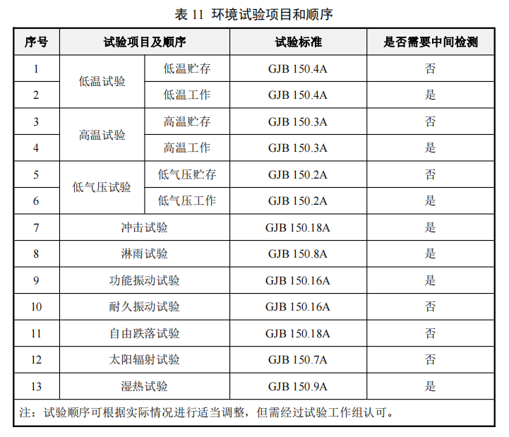
c) Testing Items and Methods
Environmental baseline tests generally only require high and low temperature and humidity tests, while transition stage environmental tests and environmental identification tests should consider the adaptability of the whole machine, subsystems, and components under various environmental conditions, thus involving more testing items. The testing items, requirements, and testing order are shown in Table 11.
05
Conclusion
In summary, this article outlines the requirements and verification methods for quantitative indicators in the general quality characteristics of military equipment.
Through the implementation and verification of reliability, maintainability, testability, supportability, safety, and environmental adaptability, it is possible to ensure the smooth implementation of military equipment at various development stages and effectively control the product quality of the equipment.
06
Postscript