

Many automotive repair friends have been asking how to use an oscilloscope, thinking that it is very difficult to use. In fact, once you really understand it, you will find that it is very simple to use.
Over the past month (four articles), I will explain some knowledge about oscilloscopes.
The first two articles will introduce oscilloscopes and their usage, while the latter two will introduce some common waveforms of sensors, actuators, and CAN bus.
First, we need to understand what an oscilloscope is and what it can do.
An oscilloscope, in simple terms, is a device used to display and record electrical quantities (voltage, current, etc.) that change over time. It is more accurate and visual than a multimeter.
PS:A multimeter usually can only reflect electronic signals using a few electronic parameters, while an oscilloscope can display a continuous, complete signal waveform.
1. Determine the operating status of the system and whether it is working normally.
2. Analyze the fault of a specific electrical appliance or circuit, pinpointing the fault location.
3. Test the network communication status between control units.
4. Can display the full picture of electronic signals, showing more accurately and visually.
Automotive oscilloscopes are mainly divided into digital oscilloscopes and analog oscilloscopes, which are further classified by the number of channels, such as single-channel, dual-channel, etc. To meet demand and simplify operation, there are also various specialized oscilloscopes.
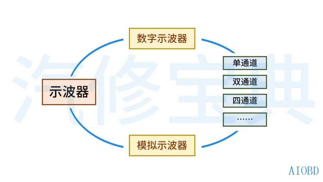
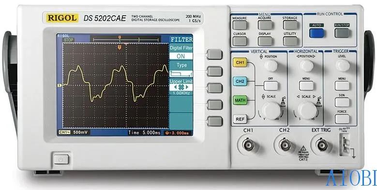
Analog Oscilloscope is an old-fashioned oscilloscope, formed by the movement of light in a cathode ray tube, and the voltage waveform displayed on the screen is called a trace.Digital Oscilloscope collects analog voltage signals, converts them into digital information, records them, and then reproduces them on the display screen.
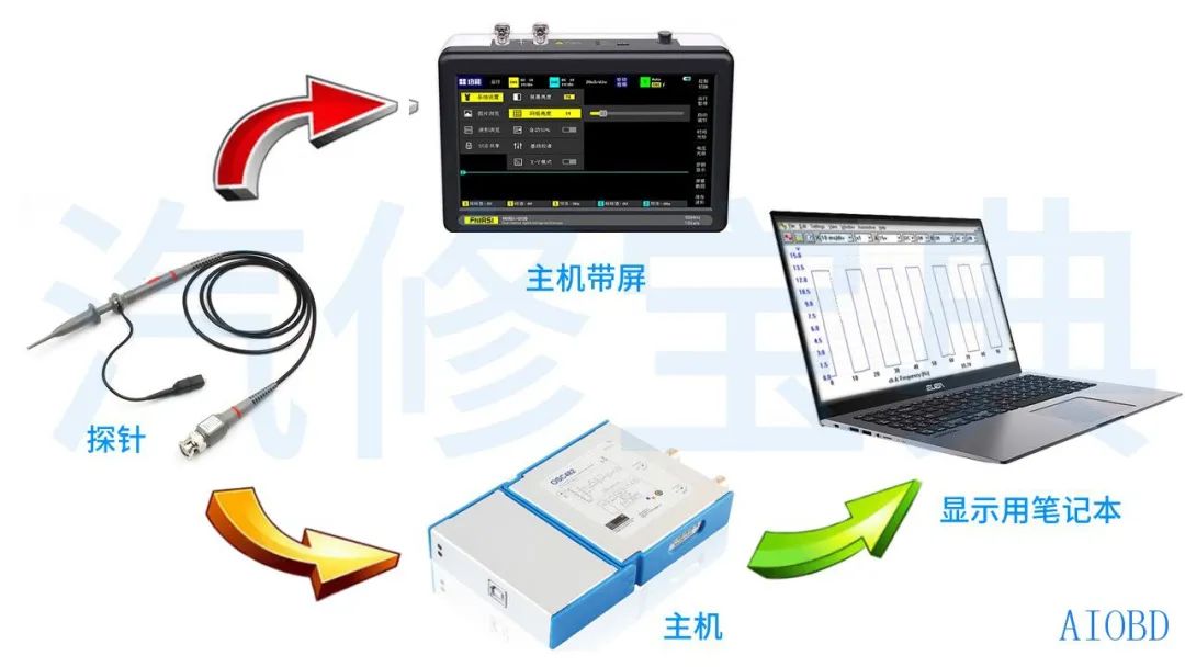
There are also some oscilloscopes that do not have a display screen and need to be connected to a computer (or mobile phone) to use, called virtual oscilloscopes. They are comprehensive in function, low in cost, and portable, with flexible and efficient software.
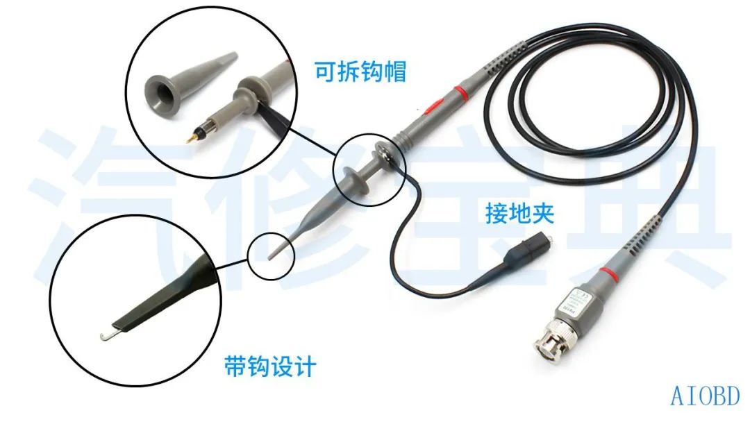
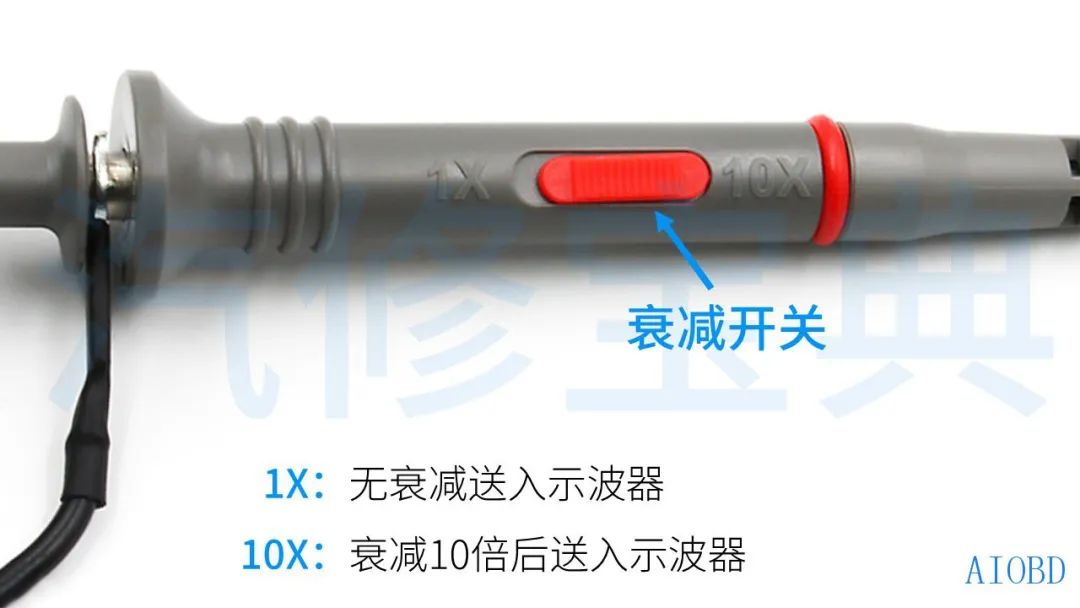
An oscilloscope generally consists of a signal acquisition device (probes, leads, etc.), a processor, and a display.
Having understood the basic concept of oscilloscopes, we now need to enter the most important part of today—some concepts of waveforms, which everyone must clarify.
Some friends may say that my diagnostic computer can read waveforms. Here is one point to clarify:
Some diagnostic computers can indeed display waveforms, but this waveform is a representation of the data received internally by the computer. If the data received or analyzed by the computer is incorrect, then this waveform is also inaccurate; while an oscilloscope “listens in” on the signals between sensors and the computer, and between the computer and actuators, starting from the source, making it more accurate.
Let’s first take a look at the types of electronic signals among automotive electronic devices:
In automotive electronic control systems, the electrical system, sensors, controllers, and actuators basically work through five basic types of electronic signals, which we will introduce in detail next~
Voltage and current signals with constant direction.
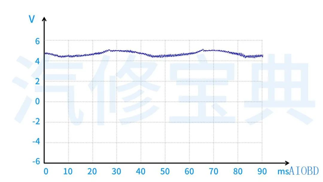
In automobiles, DC signals mainly include: battery voltage, control computer power supply voltage, throttle position, intake temperature, water temperature, fuel temperature sensors, etc.
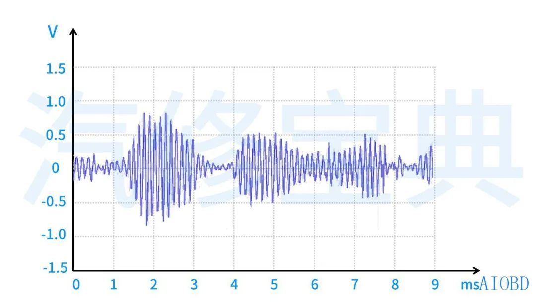
Voltage and current signals that change direction and exhibit periodic variation.
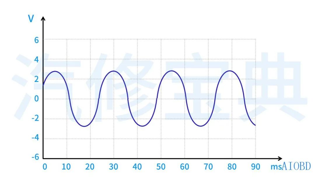
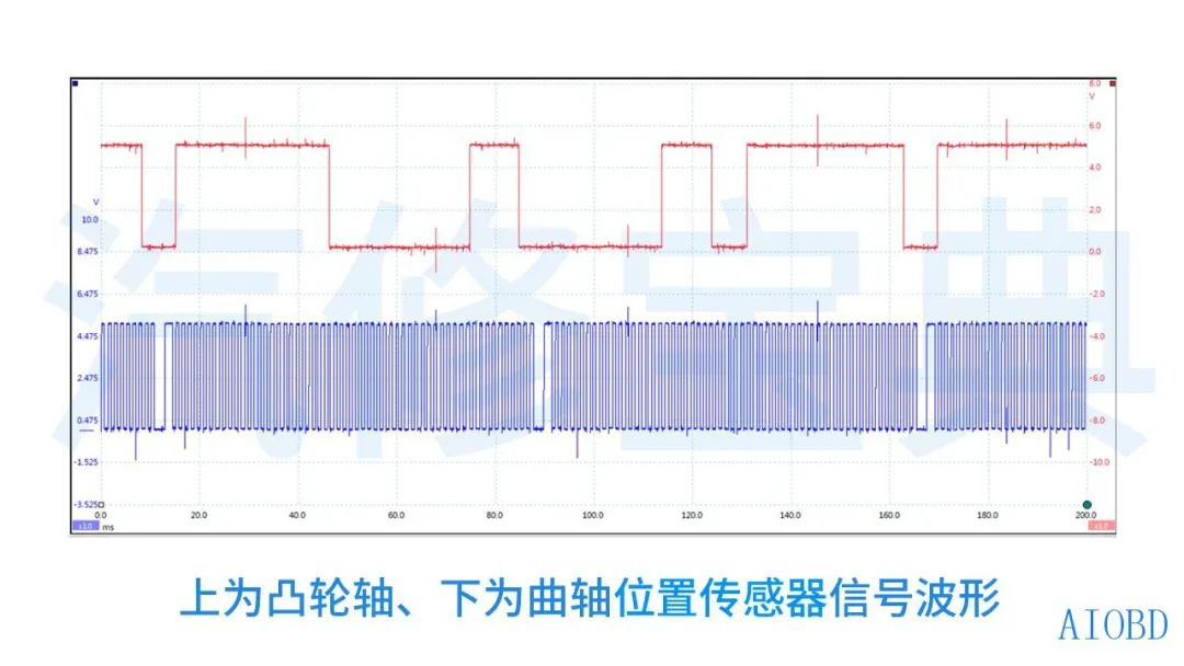
In automobiles, AC signals mainly include: vehicle speed sensors, wheel speed sensors, magnetic induction crankshaft and camshaft position sensors, knock sensors, etc.
Frequency modulated signals are signals whose frequency changes with the input signal, while the duty cycle remains unchanged. (The duty cycle is explained in detail later in the article.)
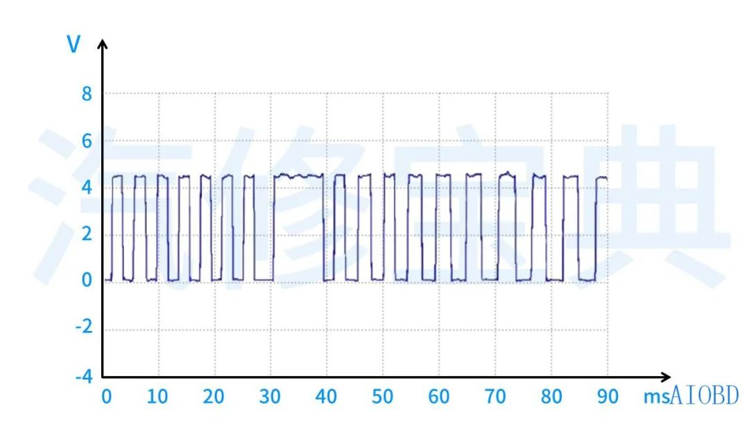
In automobiles, frequency modulated signals mainly include: photoelectric/Hall effect vehicle speed sensors, photoelectric/Hall effect crankshaft position sensors, photoelectric/Hall effect camshaft position sensors, digital mass airflow meters, digital intake pressure sensors, etc.
Pulse width modulation is a signal whose frequency remains unchanged, while the duty cycle varies with the signal.
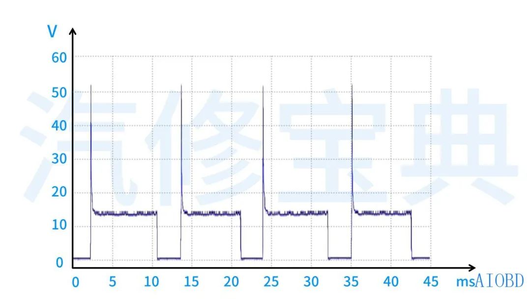
In automobiles, pulse width modulated signals mainly include idle motors, fuel injectors, primary circuits of ignition coils, various electromagnetic valves, etc.
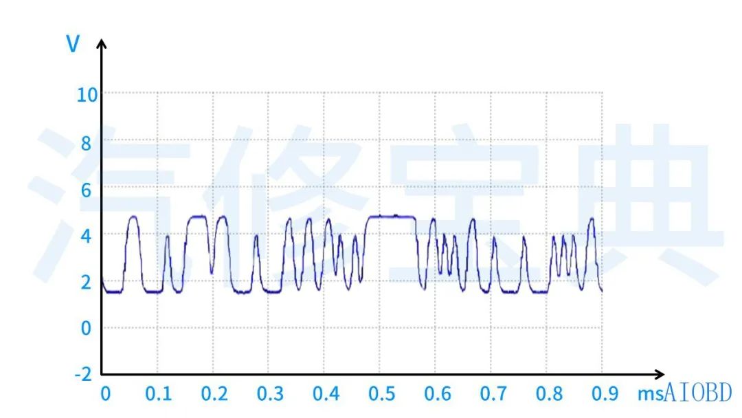
Serial data (multiplexed) signals refer to the transmission signals between computer control modules.
In automobiles, serial data is generated by control modules such as PCM and BCM.
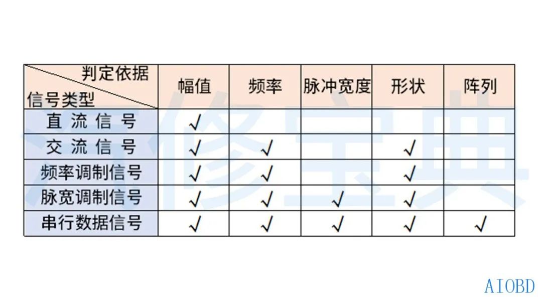
Knowing the types of signals, we now need to analyze waveform signals based on which values. In general, there are five main criteria for judgment:
Five Criteria for Electronic Signal Judgment
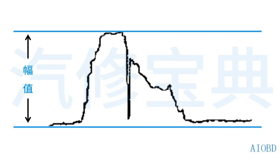
Amplitude refers to the voltage at a certain point of the electronic signal or the difference between the maximum and minimum values.
Frequency refers to the number of cycles of signal variation per second, which is the number of loops of electronic signals per second (Hz).
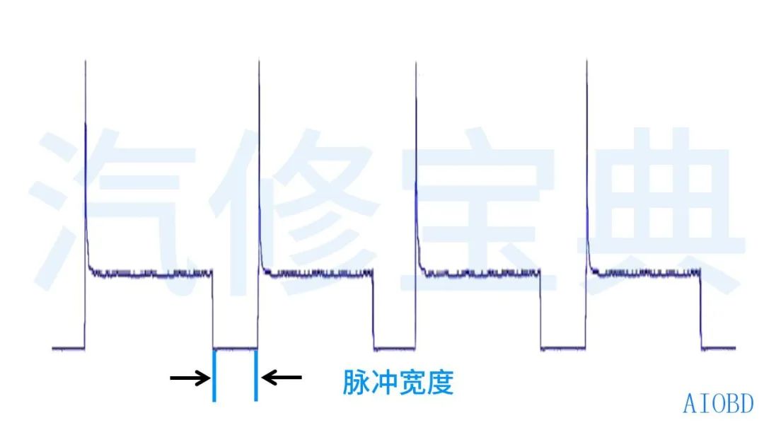
Pulse Width refers to the time occupied by the electronic signal or the duty cycle. It can be understood as the excitation time of the electromagnetic valve, usually measured in milliseconds (ms).
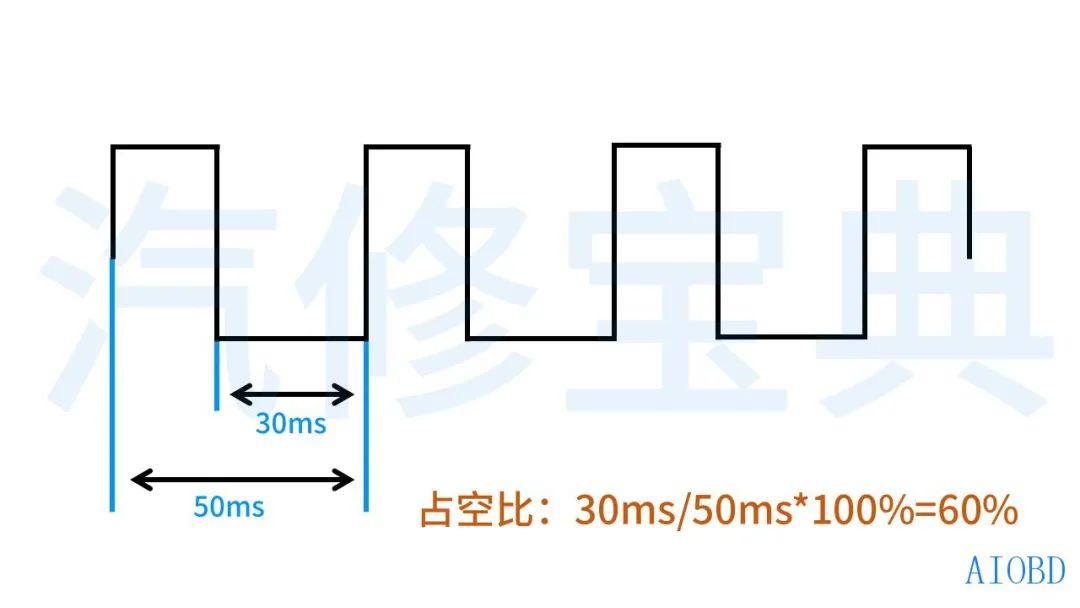
Duty Cycle: The ratio of the on-time to the total time within a pulse cycle. This is the ratio of the pulse width to the signal period, expressed as a percentage. For example, if the pulse width is 30ms, the duty cycle is: 30ms/50ms*100%=60%.
Shape refers to the external characteristics of the electronic signal, mainly including: curve lines, profiles, rising edges, falling edges, etc.
Rising Edge: The edge of a pulse signal that jumps from low voltage to high voltage is called the rising edge, also known as the leading edge.
Falling Edge: The edge of a pulse signal that jumps from high voltage to low voltage is called the falling edge, also known as the trailing edge. 
Array refers to the repetition mode of the electronic signal, such as the synchronous pulse signals at the top dead center of a cylinder, or the serial data stream related to the cooling water temperature signal sent to the decoder.
For different signal waveforms, we need to use different judgment criteria for evaluation. During the judgment, there may be one or more criteria used.
I have roughly organized this for everyone~
Alright, today we will pause here regarding the basic concepts of oscilloscopes and waveforms.
This article mainly aims to give everyone an understanding of oscilloscopes, signals, and waveforms. In the next issue, we will discuss the specific usage methods of oscilloscopes, so don’t miss it!
If you find the article good, don’t forget to give a “like” and “look” to let me know you are reading. If you have any questions, feel free to leave a message to discuss together.
