Introduction to AnOs
AnOs is an embedded time-partitioned real-time system developed based on the ARM M4 series, modeled after the VxWorks653 approach.
https://gitee.com/personal_chenjl/AnOs
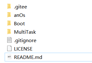
The development environment uses Keil uVersion5.
The example program runs on the STM32F427 controller.
The system aims to serve as an operating system application in high-security domains.
Software Architecture
The system consists of BOOT, OS, APP1, APPN..
The BOOT is responsible for configuring the system clock at startup, entering the firmware mode to flash the OS or various partition tasks; or directly entering the OS.
The OS is a real-time time-partitioned operating system that manages the scheduling of various task modules, provides drivers for peripheral interface resources, and protects the operation of each partition task. APPn represents each partition task, with the corresponding code developed by the actual application party.
The various partitions communicate with each other using shared memory.
Installation Tutorial
The source code provides two example task partitions, one of which controls the LED light’s working state at a cycle of 1s; the other outputs the string “abc” from serial port 1 at a cycle of 1s.
The driver program provides an example of a GPIO-controlled LED light and a COM1 driver interface.
Using a downloader, download BOOT to 0x0800000 FLASH address, OS to 0x08008000, APP1 to 0x08020000, and APP2 to 0x08040000. Then reset and run the target program to achieve program execution.
Porting Instructions
Basic Instructions
The current application environment uses Keil for development, with the testing platform being the STM32F42X series. Currently, theoretically, most of the ARM-3 and ARM-4 series are supported, but they require a hardware floating-point unit and an MPU memory protection unit (optional).
BOOTLOADER
The target board should have at least one USART1 port for the BOOTLOADER upgrade, which is the upgrade method supported by the current version. The BOOTLOADER is flashed at address 0x08000000, occupying 32KB of space. It runs first after power-on reset. The BOOTLOADER mainly configures the system clock, such as using an external clock and configuring the working frequency and bus master frequency.
OS
The OS needs to configure the ROM usage range for each APP, the RAM usage range, as well as the shared memory range and access permissions. If an MPU is present, it will enable the MPU for access protection; configure the working cycle and priority for each APP; the stack size used by each APP; and provide driver interfaces for the underlying hardware device resources. The example includes drivers for LED lights and COM ports.
The OS is downloaded to address 0x08008000, occupying 32KB of space. The OS dynamically checks the safety of the stack space during operation and protects the operating space of each partition task under the condition of enabling the MPU function.
APP
Each application program developed according to the task requirements accesses the underlying resources by calling the operating system interface functions; data transmission between APPs is achieved through shared memory, and event notifications can also be used. Each APP project must use the provided OS library during configuration, and when configuring ROM and RAM memory, it is crucial to set the correct address range according to the previously agreed space. Otherwise, the OS will consider it an illegal partition task and will not run.
Default Parameters
- Using a 12M external crystal oscillator
- Main frequency configured to 168M
- Using GPIOC.Pin3 to control the LED light
- Using GPIOA.Pin9 and GPIOA.Pin10 as USART1 device interfaces
Example Demonstration Process
1. Open the RTOS_APP.uvmpw workspace in the MultiTask directory
2. Modify the PLL_M macro in the Boot/start/boot.c file of the osBOOT project according to the actual oscillator frequency and then compile
3. Modify the hardware device configurations in the AnOs/Drv/DrvLed.c and DrvUart.c files and then compile
4. Set osBoot, AnOs, App1, and App2 as active projects in the workspace, and then download them to the target board
5. Reset the target board, and the LED will blink every 2 seconds, while the serial port will output the string “abc” every 1 second
This article is sourced from the internet to freely convey knowledge, and the copyright belongs to the original author. If there are copyright issues, please contact me for deletion.
Notice
Due to recent changes in the WeChat public account’s push rules, to prevent being unable to find it, you can star it to keep it on top, so that every article pushed will appear in your subscription list.
You may also like:
Application of Flexible Arrays in Actual Projects?
Useful | Using protobuf-c on Embedded Platforms
C Language and Embedded Key Knowledge: Callback Functions
Practical | Teach You to Build an Embedded Web Server in 10 Minutes
Reply 1024 in the public account chat interface to obtain embedded resources; reply m to view the article summary.