1


Introduction
UDS (Unified Diagnostic Services) is a very important diagnostic protocol in vehicles. However, unless you can access an actual project, I have not seen any open-source boards that can perform real UDS diagnostics; purely discussing theory is not very interesting.
I bought a set of UDS_bootloader source code on Xianyu. Currently, I have successfully run several UDS service functions. Here’s an article to introduce how to practice UDS diagnostics using an STM32 development board. The accompanying firmware will also be uploaded, so you can buy the board and flash it for practice.
2


Environment Configuration
Hardware
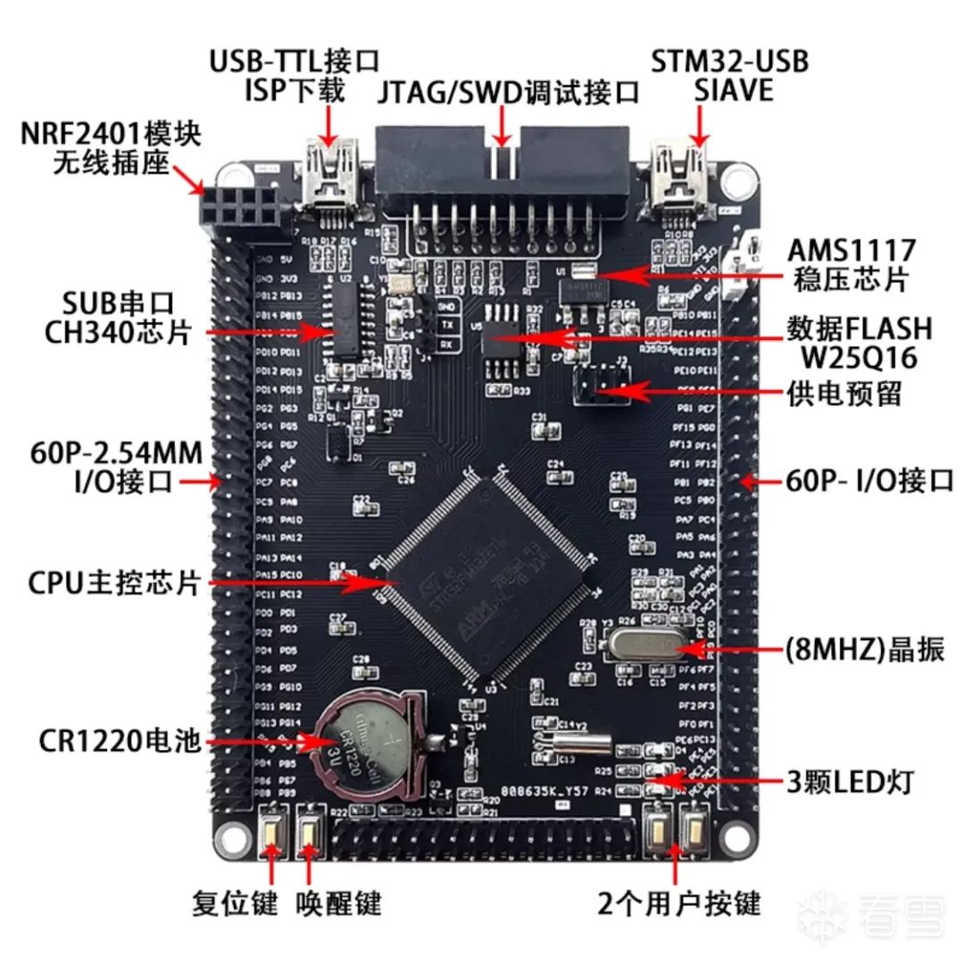
STM32F103ZE development board, used to run our UDS code.
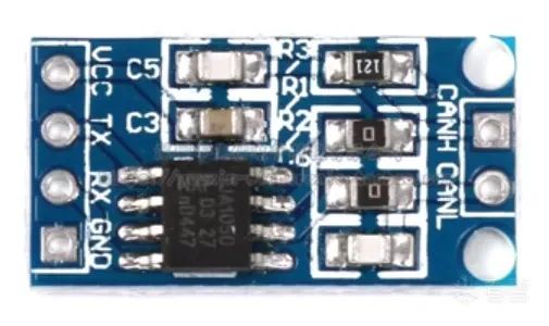
TJA1050 CAN controller interface module, used to convert CAN signals. The default ones sold on Taobao do not come with pin headers, so if you have a soldering iron, you can solder on the pin headers for easier connection with DuPont wires.
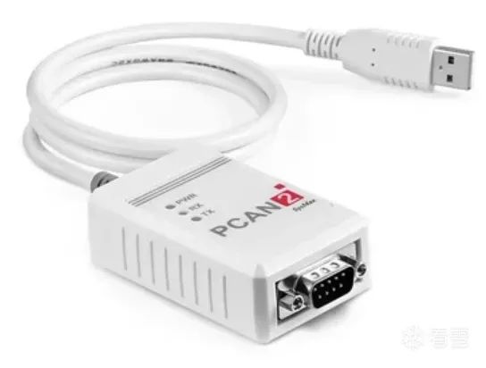
CAN debugging instrument, used to establish CAN communication with STM32. The brand does not matter; I am used to PCAN.
Jlink or STlink (mainly for flashing firmware; it’s best to buy one with this ribbon cable; otherwise, you’ll have to connect DuPont wires according to the pin definitions).

You will also need some DuPont wires to connect these hardware devices.

Software
Two main software tools are used: one is Jflash (https://www.segger.com/products/debug-probes/j-link/tools/j-flash/about-j-flash/#software) for flashing firmware. Of course, if you are using another debugger, just choose the corresponding software. The other is TSMaster (https://github.com/TOSUN-Shanghai/TSMaster/releases) for CAN communication (I must say TSMaster is very user-friendly).

Hardware Connection
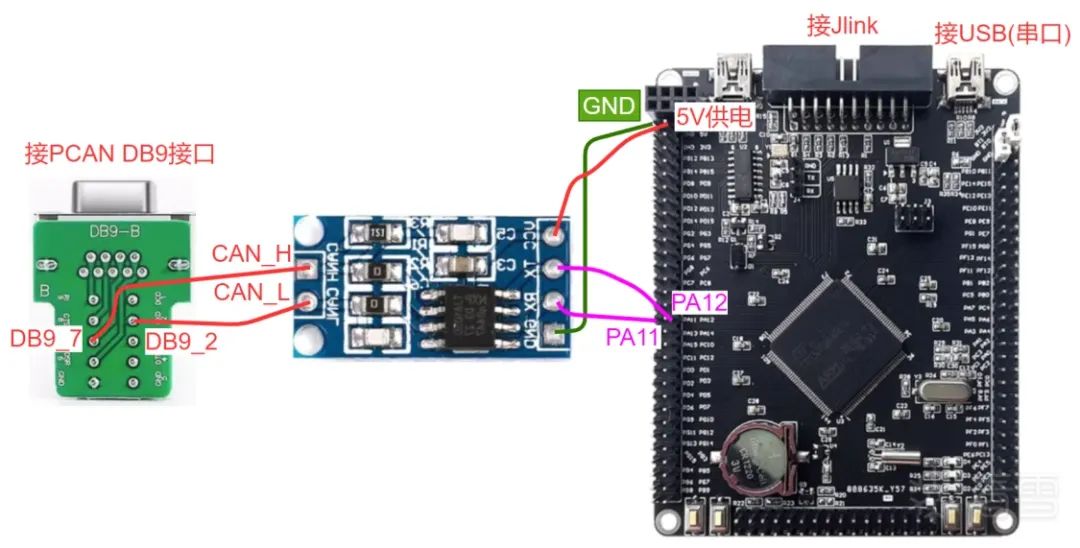
Jlink connects directly to the STM32 development board via the ribbon cable. The USB port on the right side of the STM32 is a serial port that can view UART logs.
The RX of TJA1050 connects to PA11 of STM32, TX connects to PA12 of STM32, VCC connects to the 5V of STM32, and GND connects to the GND of STM32.
The CANH of TJA1050 connects to the CAN_H of the CAN analyzer, and the CANL connects to the CAN_L of the CAN analyzer (using PCAN as an example).
Firmware Flashing
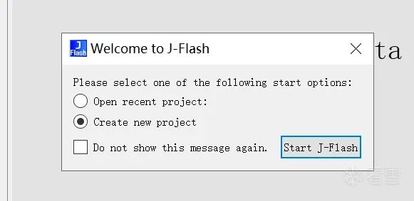
After installing Jflash, open it and select to create a new project.
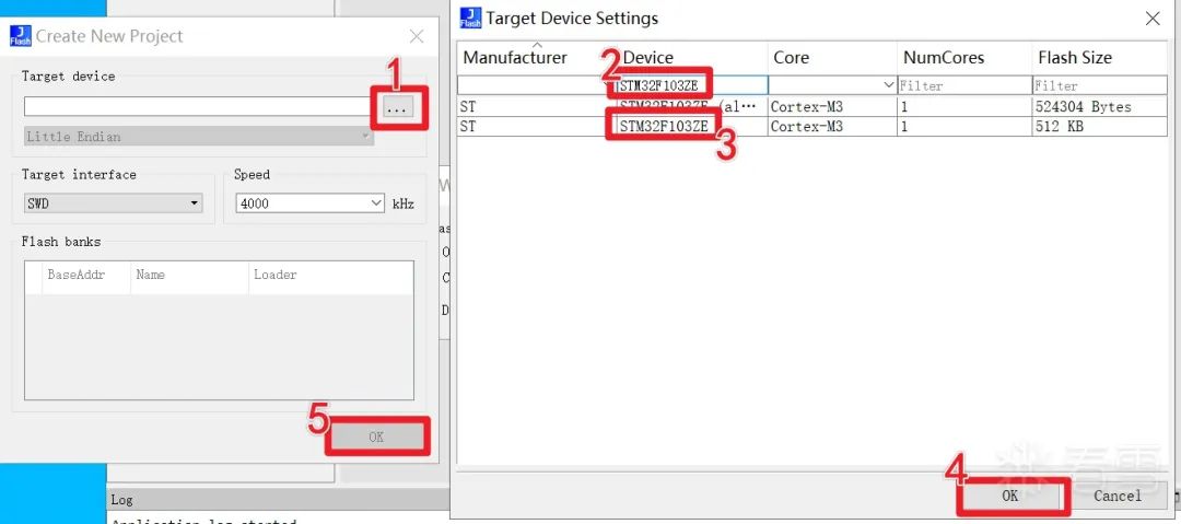
Click the three dots, input STM32F103ZE in the input box to filter it out, select the shorter one below, and then click OK.
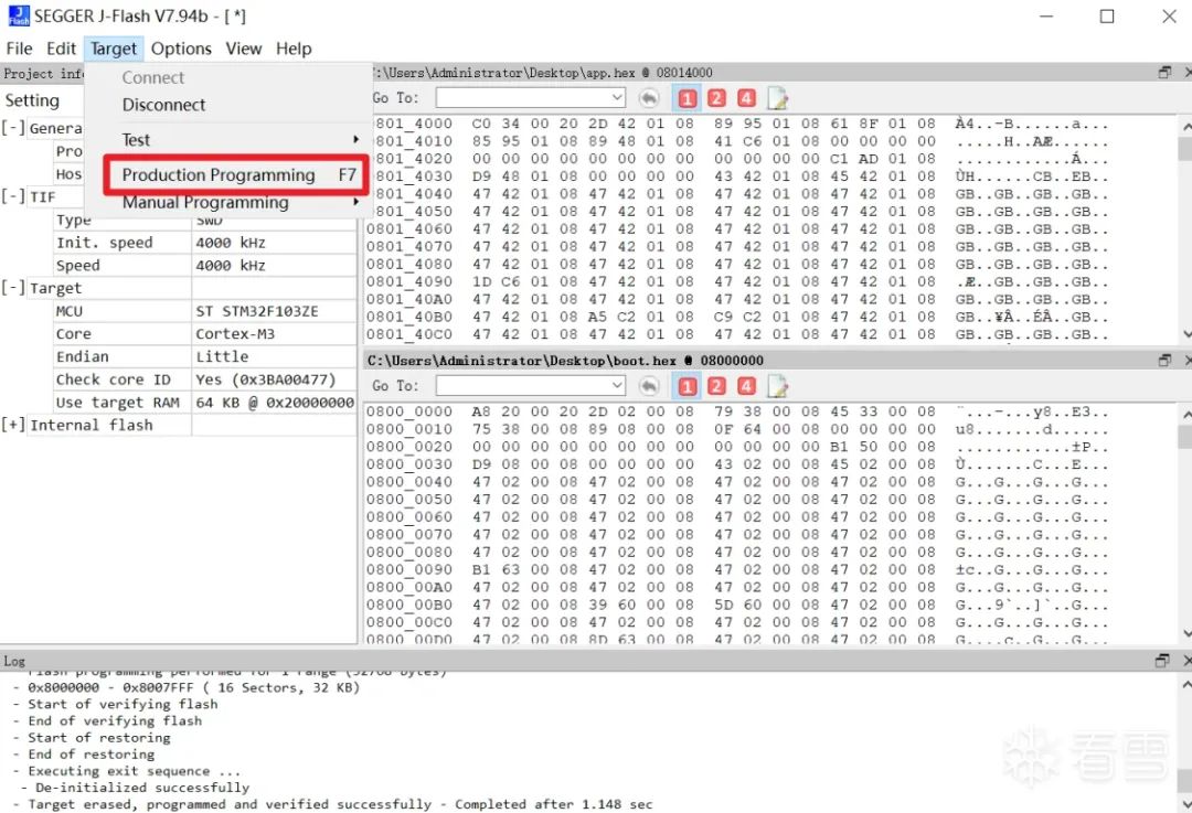
Drag both firmware files into the data file window on the right, then click Target -> Production Programming to flash the firmware (hex files contain address information, so just flash them directly).
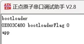
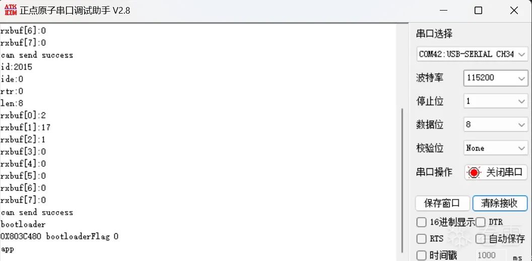
Then open the serial debugging tool, set the baud rate to 115200, press the reset button and see if there’s any output. The output below indicates normal operation.
3


UDS Communication
UDS defines a series of services, each with its own ID, known as SID (Service Identifier). Next, let’s experience UDS diagnostic communication through the development board. For specific theoretical knowledge, you can refer to other articles online or directly look at the 14229 standard. I will upload the attachment at the end of this article.
22 Read Data by ID
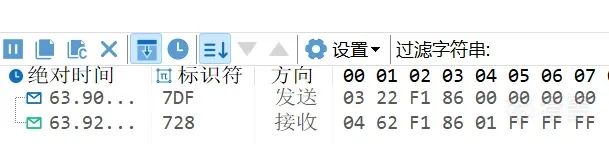
The 22 service reads data by ID. For example, the ID for reading the current session status is F1 86, so you can use 7DF # 03 22 F1 86 to read the current session. The 01 following F1 86 is the current session status.

The 14229 standard also contains many IDs, such as F1 90 for reading the VIN code (not yet implemented on the development board), and manufacturers may also define custom IDs.
10 Diagnostic Session Control
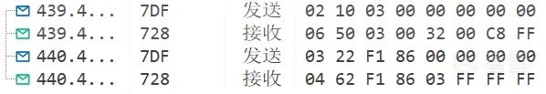
First, use 7DF # 03 22 F1 86 to read the current session.
Switch to the extended session 7DF # 02 10 03, then use 0x22 to read the session and confirm with 7DF # 03 22 F1 86. Generally, high-privilege operations, such as reading and writing data, are performed in the extended session.
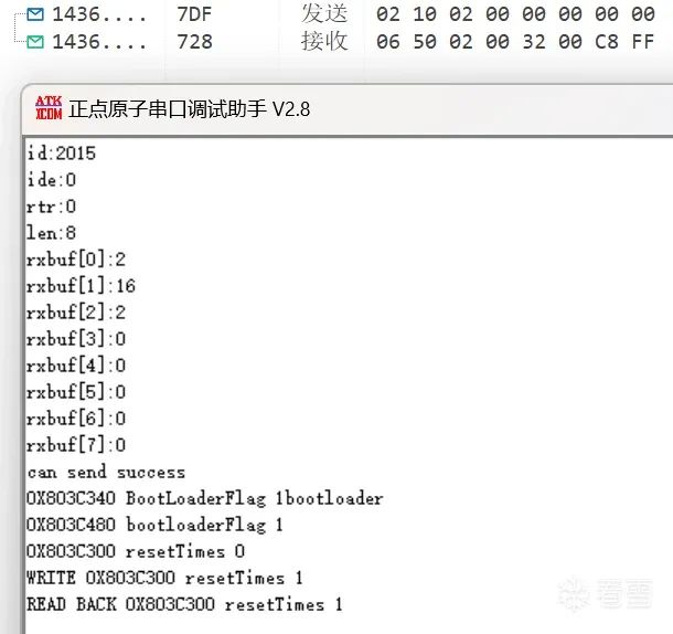
Switch to the programming session 7DF # 02 10 02. At this point, observe the serial port, and you can see that it has entered the bootloader code. Generally, this session state is used for flashing related operations.
If you do not send 3E to maintain the session after entering a non-default session, it will revert to the default session after a while.

3E Session Maintain
The 10 service mentioned earlier indicates that if you do not send the session maintain promptly, you will revert to the default session after a while. The service for session maintenance is 3E.
There are two sub-functions: 00 and 80.
7DF # 02 3E 00 indicates that a response from the diagnostic server is required.

7DF # 02 3E 80 indicates that a response from the diagnostic server is not required, which means you will not receive a response after sending.

27 Security Access
Many data and functions in the ECU require security access before they can be accessed or used. The security access process is roughly as follows: the diagnostic tool sends a security access request, the ECU replies with a seed, the diagnostic tool calculates the key based on the seed and returns it to the ECU, and the ECU checks whether the key is correct. If correct, access is granted.
At this point, it is important to distinguish between physical addressing and functional addressing. Previously, we used 7DF for functional addressing, which all ECUs can receive. Although our experiment only involves the STM32 board, this is definitely not the case in a vehicle, where there may be many different manufacturers’ ECUs. Therefore, the algorithm for unlocking security access will also vary. Thus, when using service 27, physical addressing must be used to specify which ECU.
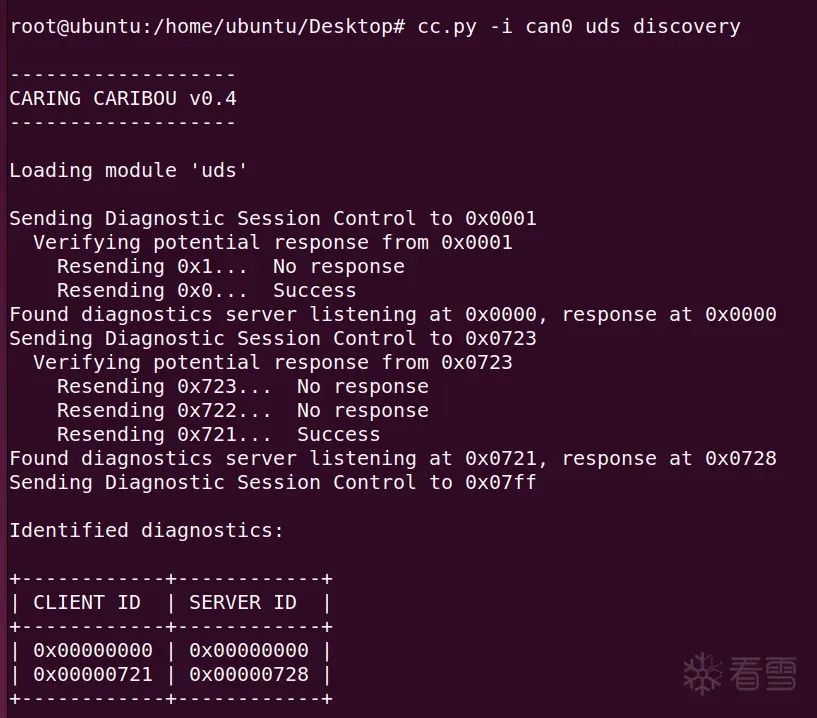
However, this is defined in the code. How do we know? You can use the tool CaringCaribou to probe. For example, my probing result is: 0x721.
Next, you can request the seed. Send 721 # 02 27 01 and find that an error occurred.

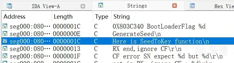
Then switch to the extended session 7DF # 02 10 03, send the maintain session 7DF # 02 3E 80, and request again to obtain the seed. However, we do not know how to calculate the key from the seed. At this point, we need to reverse engineer the firmware to analyze the logic. You can drag app.hex into IDA and open it in ARM little-endian format. Search for the string, and I added the SeedToKey string in the code for easy locating.
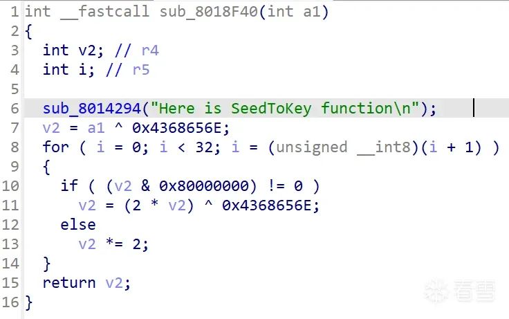
Converting it to pseudocode allows you to see the specific logic: a1 is the incoming seed, and v2 is the calculated key.
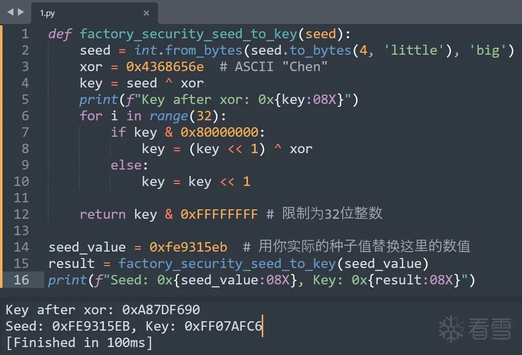
Let’s have chatGPT write a Python script to compute this.
def factory_security_seed_to_key(seed):
    seed = int.from_bytes(seed.to_bytes(4, 'little'), 'big')  # Switch endianness
    xor = 0x4368656e  # ASCII "Chen"
    key = seed ^ xor
    print(f"Key after xor: 0x{key:08X}")
    for i in range(32):
        if key & 0x80000000:
            key = (key << 1) ^ xor
        else:
            key = key << 1

    return key & 0xFFFFFFFF # Limit to 32-bit integer

seed_value = 0x34023105  # Replace with your actual seed value
result = factory_security_seed_to_key(seed_value)
print(f"Seed: 0x{seed_value:08X}, Key: 0x{result:08X}")
Request the seed.

Calculate.
Return the key, successfully accessed through security access.

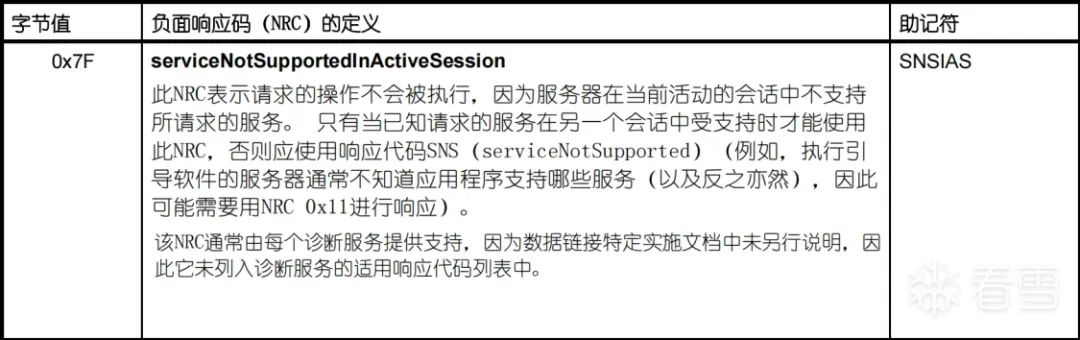
If you send the wrong key multiple times, you will receive a negative response indicating that the maximum number of attempts to unlock has been reached.


11 Reset Function
Enter the extended session, then send 7DF # 02 11 01.

You can observe the device rebooting in the serial port, which is the same effect as pressing the reset button.
4


TODO
Because the original seller was selling the UDS_bootloader, which upgrades the app through UDS, many functions have not been implemented, and there is no need to implement them. Once I organize the currently implemented functions, I will try to write some myself to create a complete UDS practice board.

Look Snow ID: yichen115
https://bbs.kanxue.com/user-home-837755.htm

# Recommended Previous Issues
1、Blockchain Smart Contract Reverse Engineering – Contract Creation – Execution Process Analysis
2、Using VS2022’s MSVC to Compile LLVM16 on Windows
3、God Blocks God – Unveiling the Mysteries of the World’s First Mobile Game Protection nProtect
4、Why DLL Files Load at the Same Base Address in Different Processes Under ASLR Mechanism
5、2022QWB Final RDP
6、Huawei Cup Graduate National Competition adv_lua