Click the blue text to follow us

There are currently over 15,000 cooperating teachers from various majors, focusing on thesis guidance and solving difficult problems in thesis writing.
Hardware Design
1.1 Main Circuit Design
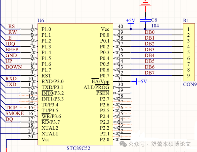
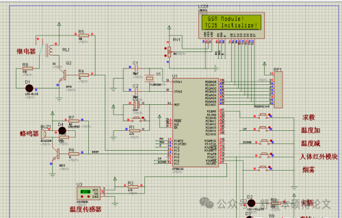
STC89C52 is a low-power, high-performance CMOS 8-bit microcontroller, featuring 60K in-system programmable Flash memory, a central processing unit, program memory (Flash), data memory (RAM), EEPROM, timer/counter, I/O interfaces, UART interface, and an interrupt system, SPI interface, high-speed A/D conversion module, PWM (or capture/compare unit), as well as hardware watchdog, power monitoring, and on-chip RC oscillator modules.
The main functionalities used in this system design are the A/D conversion module, SPI interface, timer/counter, and I/O interface. The specific schematic diagram is shown below.
1.2 GSM Module Circuit Design
The communication function between the user and the microcontroller relies on the communication interface configured by the SIM800L GSM module. The system plan includes SMS control, receiving alarm SMS, and making phone calls to check the current temperature value, which can be easily achieved as long as the network signal is smooth. The operating voltage of the SIM800L module is 3.3~5.5V, and its power consumption varies depending on the operating frequency band (900MHz and 1800MHz), being 2W (900M) and 1W (1800M) respectively.
The sending and receiving of system SMS and the automatic disconnection of calls utilize the AT command set interface. When a call is received, it will automatically hang up and reply with a SMS containing the current temperature value, all achieved through the ZIF connector on pin 40, which can handle complex functions such as power connection and bidirectional transmission of control signals. The schematic diagram is shown below.
Science & Technology
1.3 Smoke Detection Circuit Design
The MQ-2 sensor has been briefly introduced above. The structure and appearance of the MQ sensor are shown in the diagram. The MQ-2 sensor exhibits different resistance values for different types and concentrations of gases. Therefore, when using this sensor, the sensitivity needs to be adjusted. The schematic diagram is shown below:
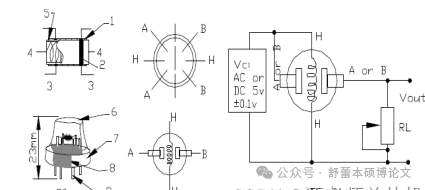
Internal structure diagram of the MQ-2 sensor
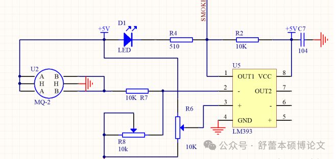
MQ-2 gas sensor module circuit schematic
Science & Technology
1.4 Temperature Detection Circuit Design
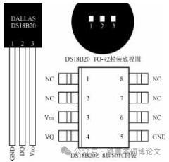
Introduction to the DS18B20 temperature sensor:
It can operate within a voltage range of 3.0V to 5.5V, and it connects to the microcontroller simply with a single wire. It requires almost no additional peripheral components, as all sensors and conversion circuits are integrated within a component resembling a transistor, with a wide temperature measurement range, capable of measuring as low as -55°C and as high as 125°C.
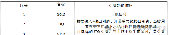
The internal structure of the DS18B20 is shown in the diagram, and the shape and pin arrangement of the DS18B20 are shown in the table below.
System Testing
2.1 System Debugging
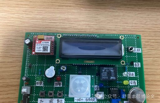
The final step requires system debugging. After all components and sensors are soldered according to the schematic, power testing is conducted. Of course, this method is most direct and convenient for relatively simple circuits, but it is not conducive to discovering problems. If there are soldering errors, more time will be wasted in searching for them. Therefore, the debugging method adopted in this design is to debug during the installation process, dividing the circuit into various modules and installing and debugging them unit by unit. The image of the successfully debugged circuit board is shown below.
2.2 Debugging Process
(1) Pre-power check
After the circuit soldering is completed, the system should not be powered on. First, carefully check whether the wiring is correct according to the schematic, whether there are poor contacts or circuit errors, and whether the pins connected to the main controller correspond to the circuit diagram. During the check, it is advisable to use a multimeter to measure directly on the pins of the components to discover if there are any poorly contacted components and complete the rectification.
(2) Power testing of each unit circuit
After completing the soldering of the unit modules according to the current direction in the circuit diagram, a simple recheck of the circuit should also be performed before powering on. If there are no anomalies, the output values of the previously debugged modules can be used as input values for the current module as the basis for power testing. If there are no issues, proceed to debug the next module.
(3) Overall power testing
Once all modules have completed power testing, the program can be downloaded to the microcontroller, and the overall system power testing can begin. It is also necessary to conduct a trial power-on to ensure that the circuit board shows no anomalies before officially conducting power testing for various functions.
This comprehensive testing mainly verifies the completion of various functions under normal system debugging conditions.
① First, adjust the sensitivity of the DS18B20, setting the alarm temperature to 50°C and displaying it on the LCD screen. By using some special methods, change the ambient temperature and observe whether the temperature value displayed on the LCD screen changes.
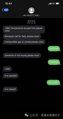
② Measure when the ambient temperature exceeds the temperature threshold, the system emits an audible and visual alarm and the GSM sends an English SMS to the user’s mobile phone;
③ When combustible gas or smoke is detected indoors, the GSM module sends an English SMS to the user’s mobile phone;
④ When someone intrudes indoors, the GSM module sends an English SMS alarm;
⑤ When calling the number associated with the inserted SIM card, the GSM module hangs up the call and sends an English SMS with the current temperature value;
⑥ When sending “#OPEN” or “#CLOSE” SMS to the GSM, the relay completes the action of closing or opening, thereby achieving control over the smart home;
⑦ When pressing the emergency button, the system’s GSM sends an English SMS to the user’s mobile phone.
Successful debugging is indicated when all functions can be normally realized. The image of successful debugging is shown in 4.2.
2.3 Problems Encountered During Debugging
(1) After power testing, the smoke sensor fails to detect smoke/combustible gas normally.
Solution: After consulting the data, it is found that the smoke sensor needs to be fine-tuned according to usage conditions:
① Adjust the COMP potentiometer, using a voltmeter to measure pin 3 of U5 (V+ input), keeping its voltage around 1.8V;
② In the absence of smoke/combustible gas, adjust the VALUE potentiometer, using a voltmeter to measure pin 2 of U5 (V- input), keeping its voltage around 0.6V;
③ To increase sensitivity, the COMP potentiometer can be adjusted to lower the voltage, while increasing sensitivity can be achieved by raising the voltage, but it must not be lower than the voltage at pin 2.
(2) All functional circuit parts are normal, but cannot interact with the GSM module.
Solution: After consulting the data, this situation may be due to the SIM800L GSM module not detecting the network signal, which prevents successful network registration and thus prevents function realization. Due to technical limitations, this module does not support telecom cards; thus, replacing it with a mobile or Unicom SIM card or moving to a location with a strong signal can complete network registration and normal functionality.
Software simulation diagram
Temperature alarm simulation
Combustible gas alarm simulation
Human infrared detection alarm simulation

Get more graduation project cases by scanning the code!
Free consultation for thesis problems!