Recommended to follow 👇 the public account below to learn more electronic technology knowledge!
The idea of layering is not a mysterious thing; in fact, many engineers working on projects are already using it. After reading many posts, I found that this concept was not mentioned, yet the layered structure is indeed very useful, and understanding it will give you a sense of enlightenment.
If I don’t understand how to drive an LCD, that’s simple; just look at the datasheet, reference others’ programs, and I can quickly make it work. However, if you don’t understand the philosophy of program design, it will bring a lot of confusion during your project development.
I have referred to various embedded books available on the market, like MCS-51, AVR, ARM, etc., but I haven’t found one that introduces design philosophy; even if there is, it is rare. Writing programs is not difficult, but how to write them well and quickly requires some experience accumulation. The ideas of structured and modular programming design are the most basic requirements.
But how to apply this abstract concept in engineering practice? It requires going through hardships during project development, summarizing some things, and abstracting them into theories, which is beneficial for the accumulation of experience and the dissemination of technology. Therefore, I would like to share some insights.
From my personal experience, there are two design philosophies that are very important.
One is the “time slice round-robin design philosophy,” which is very useful for solving multitasking problems in practice. This can usually be used to judge whether a person is a microcontroller learner or a microcontroller engineer. This must be mastered (to be introduced below). The second is the “layered masking design philosophy,” which is the layered thinking. Below, I will use the keyboard scanning program as an example to introduce today’s topic.
Microcontroller learning boards are generally designed simply, assigning keys effectively; for example, the entire 4*4 keyboard matrix is assigned to port P1, with 8 control lines, just right. This makes the program very easy to write. You just need to simply do: KEY_DAT = P1;
The port data is read in.
Indeed, in reality, things are not that simple. In actual project applications, the multiplexing of microcontroller pins is quite significant, which is very different from those so-called microcontroller learning boards.Another reason is that the general design process is “software cooperating with hardware”; simply put, first determine the hardware schematic, hardware wiring, and finally the software development, because modifying hardware is more troublesome, while modifying software is relatively easier. This is the traditional yin-yang balance philosophy in China. Hardware design and software design are inherently a relationship where you cannot have both. Making hardware design convenient can often cause significant trouble in writing software.
Conversely, if software design is made convenient, hardware design will also be quite troublesome. If both hardware and software designs are made convenient, there are only two possibilities: either the design scheme is very simple, or the designer has reached a very high level. We won’t consider so many situations; we will purely look at the problem from the perspective of commonly used practical applications.For the sake of wiring convenience, hardware often assigns IO ports to different ports; for example, the aforementioned 4*4 keyboard, with 8 wires assigned to P0, P1, P2, and P3. In that case, the scanning keyboard programs for development boards can go to hell. How do we scan the keys? I remember when I first started learning, I had to divide the program into three very similar segments for scanning each key…
Perhaps some are unwilling to accept, “Those things I spent a long time learning and using well, how can you say they are useless?” Although it sounds a bit cruel, I still want to say, “Brother, accept reality; reality is harsh…”However, the difference between humans and lower animals is that humans can create and will find ways to solve problems when faced with difficulties, so we began to ponder…Finally, we introduce the concept of “mapping” learned in middle school mathematics to solve the problem. The basic idea is to map keys from different ports to the same port.This way, the key scanning program is divided into three levels:
1) The lowest level is the hardware layer, completing port scanning, 20ms delay for debouncing, mapping port data to a KEY_DAT register, which serves as an interface for the upper driver layer.2) The middle layer is the driver layer, which only operates on the values of the KEY_DAT register. Simply put, regardless of how the hardware is wired at the bottom layer, we only need to care about the value of the KEY_DAT register in the driver layer. The indirect effect of this is that it “masks the differences in underlying hardware,” so the programs written for the driver layer can be used universally.The other function of the driver layer is to provide a message interface for the upper layer. We used a concept similar to window program messages here. Key messages can be provided, such as: press messages, release messages, long press messages, step messages during long presses, etc.3) Application layer. This is where key functionality programs are written according to different projects, belonging to the uppermost layer of programs. It uses the message interface provided by the driver layer. The idea of writing programs at the application layer is that I don’t care how the lower layers work; I only care about key messages. When key messages come, I execute functions; when there are no messages, I do nothing.Below is a simple, commonly used example to illustrate the use of this design philosophy.When adjusting the time on a stopwatch, it is required to hold down a certain key to continuously increase the time. This is very practical and widely used in actual home appliances.Before looking at the following things, everyone can think about whether this is difficult? I believe everyone will loudly answer, “Not difficult!!” However, I will ask again: “Is this troublesome?” I believe many people will definitely say, “Very troublesome!!” This reminds me of the messy structure of the key programs I wrote when I first learned microcontrollers. If you don’t believe it, you can try writing it with the 51; that way, you will better appreciate the advantages of the layered structure discussed in this article.
Two keys are assigned to P10 and P20, respectively, as the “increase” and “decrease” keys, requiring continuous increase and decrease functions when the key is held down.
Assuming the keys are pulled up, high level when no key is pressed, low level when a key is pressed. Additionally, to highlight the problem, the debounce delay program is not included here; in actual projects, it should be added. There are various ways to pass parameters in C language functions; here, as an example, the simplest global variable is used to pass parameters. Of course, you can also use unsigned char ReadPort(void) to return a key reading result, or even void ReadPort(unsigned char* pt) to use a pointer variable to pass the address for direct modification of the variable. There are many methods, which depend on each person’s programming style.
1) Start writing the hardware layer program to complete the mapping
#define KEY_MIN  0X01
#define KEY_PLUS  0X01
unsigned char KeyDat;
void ReadPort(void) {
    if (P1 & KEY_PLUS == 0) {
        KeyDat |= 0x01;
    }
    if (P2 & KEY_MIN == 0) {
        KeyDat |= 0x02;
    }
}
C language should be easy to understand, right? If KEY_PLUS is pressed and P10 reads low level, then the result of P1 & KEY_PLUS will be 0 (xxxx xxx0 & 0000 0001), satisfying the if condition, entering KeyDat |= 0x01, which sets bit0 of KeyDat to one, meaning that KEY_PLUS is mapped to bit0 of KeyDat.KEY_MIN maps to bit1 of KeyDat in the same way. If bit0 of KeyDat is 1, it indicates that KEY_PLUS is pressed, and vice versa.There’s no need to think of it as mysterious; mapping is just that. If there are other keys, use the same method to map them all to KeyDat.2) Writing the driver layer program
If we think of KeyDat as port P1, then this is just like the standard scanning program of the learning board, right? Yes, this is the purpose of the lower-level mapping.3) Writing the application layer program
According to the messages, the hardware layer must be separated. However, the requirements for the driver layer and application layer are not so strict; in fact, for some simple projects, there is no need to separate these two layers; just adapt flexibly according to actual applications.
In fact, writing programs this way is very convenient for portability; by simply modifying the hardware layer’s ReadPort function according to different boards, the driver layer and application layer can use much code directly without modification, greatly improving development efficiency. Of course, this key program will have certain issues, especially when dealing with the mixed use of normally closed keys and momentary keys. This is left for everyone to think about; anyway, problems can always be solved, although methods may vary in quality.
2. Time Slice Round-Robin Design Philosophy
First, let’s introduce today’s topic with a small example. Imagine a basic home appliance control board, which will contain at least: LED or digital tube display, keys, and relay or thyristor outputs. The digital tube requires dynamic scanning every 10ms to 20ms, and the keys also need about 20ms of debounce delay. Have you realized that these times are actually happening simultaneously?
Recall how our textbooks taught us to debounce keys? That’s right, a dead loop, absolutely a stationary dead loop, using instructions to time. This naturally raises a question: if the microcontroller is stuck in a dead loop, what about other tasks? What about the dynamic scanning of the digital tube?
The only solution is to perform the scanning after the key scanning, which will certainly cause the digital tube to flicker; if the scanning time is too long, shortening the debounce time will not solve the problem. Imagine if we have many other tasks that also need to be done simultaneously?
One solution is today’s topic, the idea of time-slicing scanning. Of course, it is not the only solution; I have always used it and think it is a very good idea that can solve many practical problems. Boldly speaking, the idea of time-slicing scanning is also the core idea of microcontroller programming; whether you believe it or not, it’s up to you to judge.
Implementation of Core Ideas:
Actually, it involves several stepsFirst, use RTC interrupts to time; I usually set the RTC interrupt time to a little shorter, around 125us, which is needed to decode infrared remote control codes. RTC timing is quite accurate, and we should make full use of it.Second, place three (quantity is adjustable) timers in the RTC interrupt service routine (essentially, they are counters). My habit is to set 2ms, 5ms, and 500ms as benchmark times for the entire system to call, so they must be quite accurate; we can adjust them using an oscilloscope, which is not difficult.Third, place a dedicated time-handling subroutine in the main program loop. (Note: microcontrollers do not stop; they are always running in a continuous loop, which seems a bit different from what we learned in school; I was asked this question in an interview…) Place all time handling in the time-handling subroutine; this is very convenient. A microcontroller system needs to handle at least 10 to 20 different times, requiring 10 to 20 timers, and many require simultaneous asynchronous operation. If each were handled separately, it would be quite troublesome.Fourth, “programs run to wait, not stand still to wait”; this may sound a bit mysterious. An engineer who joined the company with me mentioned this issue, and I think it is also a relatively important idea of the time-slicing system, so I also named it that; below, I will elaborate.Fifth, let the programs speak; comments should be as detailed as possible; you can understand the code directly by looking at the comments.
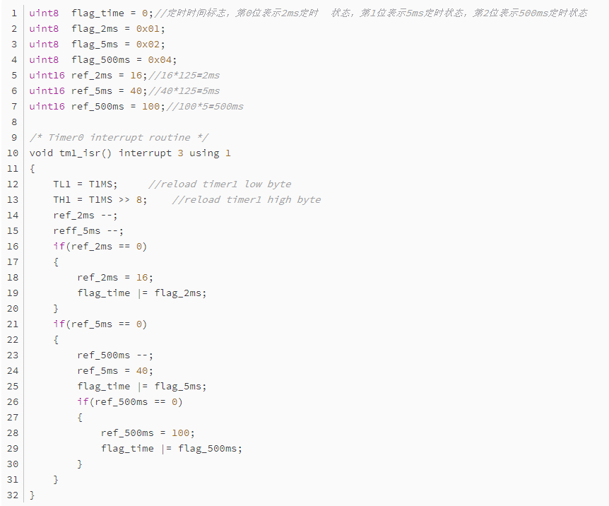
(1) First, the interrupt service program part:Interrupt every 125us
————Generate several benchmark times—–
(1) The ref_2ms register continuously decreases by 1; it decreases 16 times per interrupt, so the time elapsed here is 125us × 16 = 2ms; this is what we call a timer/counter. Thus, we can rely on a system RTC interrupt to achieve many timing times we need.(2) Set the 2ms timing end flag, which is provided for the time-handling program; this is a framework for a timer. The following 5ms timing is identical.This program also uses a block framework, which is quite convenient, but it is unrelated to today’s topic; I will write about this later when I feel frustrated. The above program is the timer in the interrupt service program, timing 2ms, 5ms, and 500ms, with the overflow flag_time marking the completion of the timing; the program can read this flag to determine whether the timing has arrived.
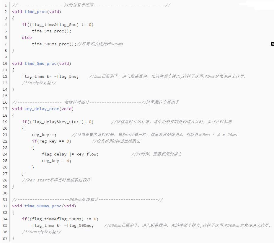
(2) Now let’s look at the unified time service subroutine
Above, we used the 20ms debounce timer as an example. Once understood, we can completely mimic that timer and place many more timers below. Each timer counts simultaneously, and the first to finish counting will turn itself off and set the corresponding flag for other programs to call, without affecting other timers!
Thus, we can place many timers here. Generally speaking, having ten or twenty is not a problem, fully satisfying a microcontroller system’s needs for multiple timing. The structure of a single timer is quite simple: first check whether the timing flag is allowed to enter timing; then a dedicated register counts up or down. After adding or subtracting the corresponding value, the timer is turned off, and the necessary flags are set.At this point, we can obtain all the timing we need; isn’t this very convenient? Let’s take a look at what the microcontroller is doing during this time.
With the interrupt timing of 5ms or 500ms, the overflow flag only becomes effective when it enters the above timing program; other times are spent doing other tasks. Moreover, when entering the above timer, it is evident that it is not stuck in a dead loop; it simply adds or subtracts a register and exits, taking an extremely short time, probably around 5us to 20us, having no impact on the execution of the main program.
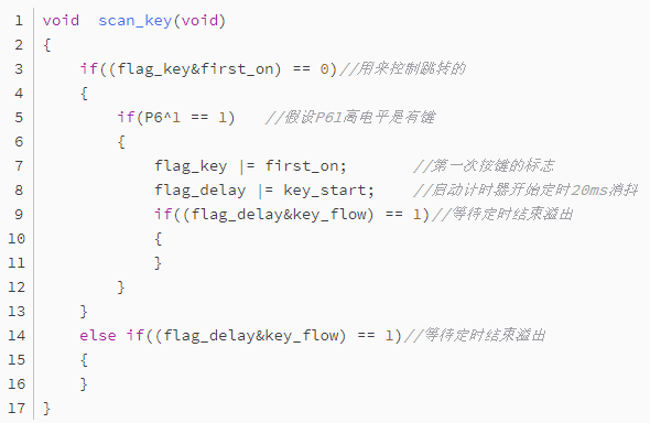
(3) Now let’s see how to call it specifically
We previously discussed the key debounce timing issue; now we will use the method introduced above to see how to solve the problem. Key handling is also an important foundational knowledge, but it is beyond the scope of this discussion, so we will only discuss how to solve timing issues; we can continue discussing key issues next time, hoho~~~
It goes something like this: determine when a key is present; if not, jump out; if so, start the debounce timing. On the second entry, directly control the past judgment time with the flag bit.Similarly, in waiting, this is the last point mentioned: we are running to wait, not standing still to wait. Compared to dead loop timing, during the time when we have not timed to 20ms, what is the microcontroller doing?
In a dead loop, it is certainly waiting in place, doing nothing. However, in the above program, it only checks if the timing is sufficient; the actual timing is done in the unified time subroutine. If the timing has not arrived, it jumps out and continues running other programs until the timing is reached. The microcontroller checks whether flag_delay and key_flow meet the conditions and starts the key handling program. During this period, the microcontroller is doing other tasks, and it has enough time to run other programs without wasting time on debouncing.
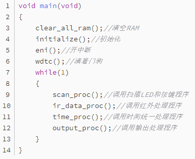
(4) Let’s take a look at my main program loop
This is the loop body I use, where all functions are written in subroutine form; when needed, they can be attached easily. This way, the overall loop body allows the microcontroller to continuously execute this loop. If the entire program adopts the time-slicing sweeping idea mentioned above, the time to complete a full loop is quite short; isn’t it somewhat similar to the idea of a computer?
A computer, no matter how fast, does not process multiple tasks simultaneously; instead, it processes one at a time, then cycles through very quickly, making us feel that it is processing multiple programs simultaneously. I believe what I ultimately want to express is just that.
In my view, with this idea supporting it, writing microcontroller programs becomes relatively easier; the rest is just concentrating on using programs to realize our ideas. Of course, this only describes one feasible method, not the only one. If anyone has good ideas, please share them! Writing programs is an art; it’s easy to write them, but writing them well and elegantly is quite difficult.
The Difference Between MOSFETs and IGBTs
Common Communication Interfaces for Microcontrollers: I2C, SPI, UART, etc.
Can Microcontrollers Replace PLCs?
How to Learn Microcontrollers from Scratch: A Beginner’s Progression Path
How to Understand the Rail-to-Rail Characteristics of Operational Amplifiers? This Article Will Open the Door for You!
What is the Difference Between SRAM and DRAM?