[Introduction]
Since the release of the iBox related textbooks, many friends have expressed a desire for a detailed explanation of software development.
Therefore, we will gradually share some details about IoT development with STM32 on the iBox.
Today is the first chapter, where we will introduce how to port the standard official code (bare metal, no OS) to the iBox development board to control the LED blinking. Although this is a simple experiment, we hope to provide you with a different experience.
[1. Install the Compilation Tool Keil]
1. Why choose Keil
Before this operation, we should explain why we chose “Cortex-M”, why we chose “M3”, and why we chose “ST”. This could easily lead us off track. So let’s keep it simple; the reasons boil down to the following dimensions:
1. Cost
2. Power consumption
3. Development workload
4. Ecosystem
5. Learnability and popularity
As for why we chose Keil instead of IAR or GCC, it’s because of its simple configuration. In terms of the richness of supported chips, IAR is a good choice. For experienced developers, the differences in tools are minimal; just like hardware experts, the differences in drawing tools are not significant.
KEIL and IAR Systems are both suppliers of embedded system development tools and services (IDE). The former was established in 1986 and is headquartered in Germany (now acquired by the well-known British ARM company); the latter was founded in 1983 and is headquartered in Sweden.
Their most famous products are KEIL uVision IDE and IAR Embedded Workbench.
Most developers have probably used them because they both support various versions of MCUs well. Over time, you become accustomed to different development environments, and whether you find them convenient or not varies from person to person. However, we must consider this: choosing the most suitable and efficient tool for oneself is the best approach.
KEIL’s IDE interface is quite user-friendly and approachable.
IAR, on the other hand, has a clean and clear interface, giving an overall professional feel. It’s not easy to get started, but once you do, it feels manageable.
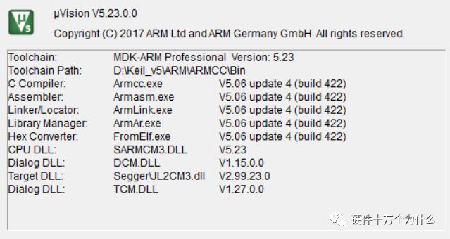
The version of KEIL we chose is:
2. Download and Install Package
Link: https://pan.baidu.com/s/1u955P7trvFYMOAghlj0Y2w Password: y4gy
Since Baidu Netdisk has started limiting speed since the “360 Netdisk” was discontinued.
So we can use other unlimited speed download tools to download.
Save the above content to your own cloud disk, then use the tool below to download.

Pandownload Tool Download Address:
http://pandownload.com/
3. Installation
The downloaded compressed package is divided into three parts. After downloading all of them, unzip it, and there are five files in the folder.
First, install the MDK523 installation package, which is 737MB, and then install the MDKCM523 installation package.

There are no special points to note during the installation process; just click NEXT all the way.
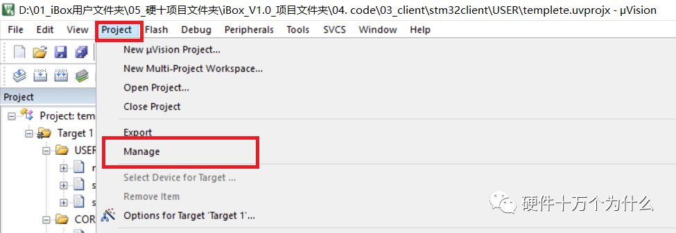
After the installation is complete, click on the Project menu, then Manage, and select Pack Install.
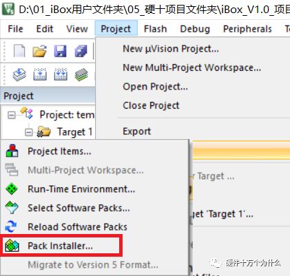
When the Pack Installer window opens, select the File menu, then Import, and choose to import the three PACK files you just downloaded.

4. Cracking
After the installation is complete, the only thing left is cracking.
The cracking tool is for educational purposes only and not for commercial use.
http://www.hw100k.com/forum.php?mod=viewthread&tid=3506&extra=
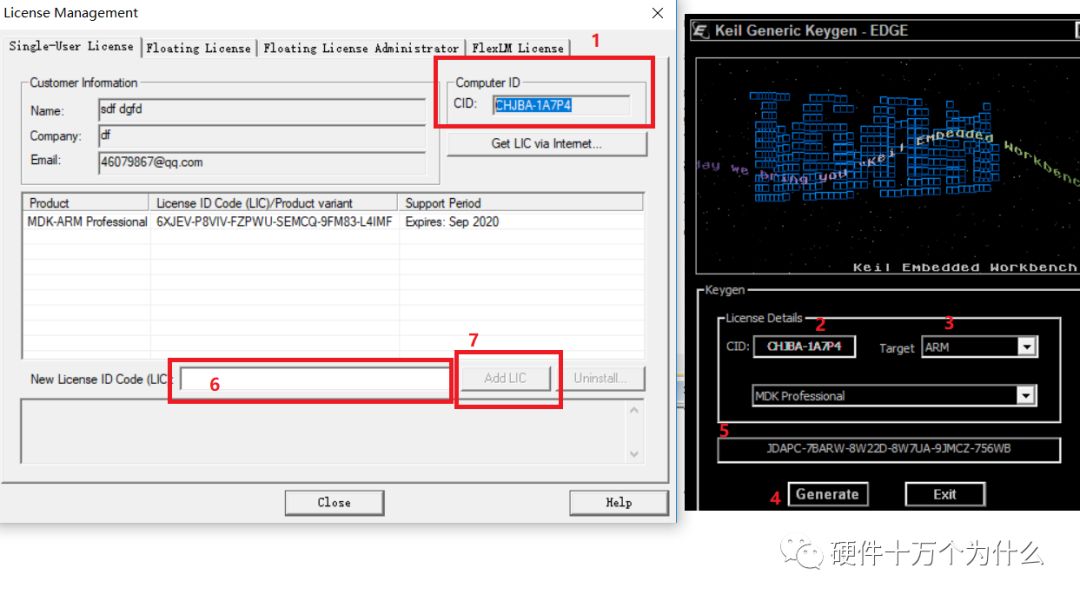
Cracking consists of 7 steps:
1. Click the menu File -> License management to get CID.
2. Copy the CID to the cracking tool.
3. Select Target as ARM.
4. Click the Generate button to create a serial number.
5. Copy the serial number.
6. Paste it into the LIC field.
7. Click ADD LIC.
Cracking is complete.
Important: When cracking, run Keil with administrator privileges.
If you try to run the project hastily without cracking, you will get an error with the following prompt:
Check that your license details are correct in the License Management dialog of MDK. Additional information is available at:
http://www.keil.com/support/man/docs/license/license_management.htm
Thus, the installation and cracking are complete.
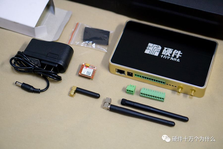
After installation, we can take out our iBox hardware development board.
[2. Download and Use ST Official Source Code]
During our learning process, it’s best to learn to use the official source code. Code from other development boards is recommended only as a reference, as everyone has their own coding habits and there may be some differences.
Different companies have different requirements for code standards and structure.
Therefore, we will start from the official code. Code according to your company’s requirements and your own understandable habits, improving through practice.
In short, we should master the code, be proficient, and not rush through it.
1. MCU
Let’s briefly introduce the hardware system of our iBox IoT development board:
The core chip is STM32F103ZET6.
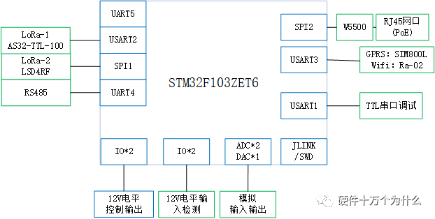
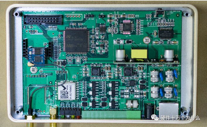
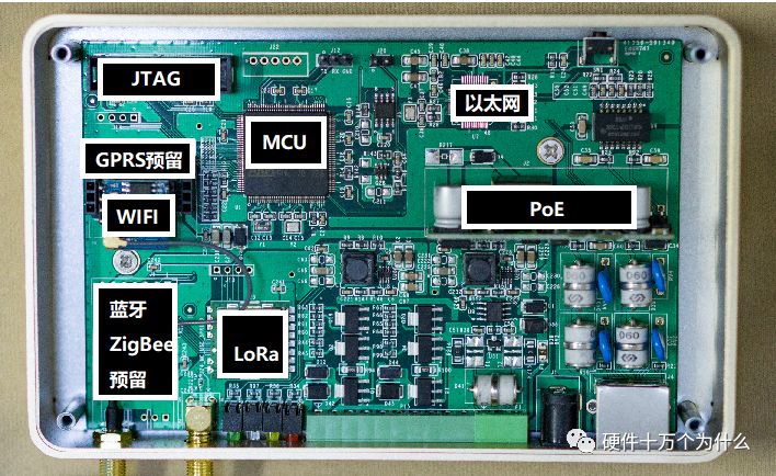
Schematic PDF download link:
http://www.hw100k.com/forum.php?mod=viewthread&tid=3501&extra=page%3D1
2. Using ST Official Website
If you are familiar with it, you can skip this section. However, based on my observations, many engineers who have long used STM32 have not actually looked closely at the official website.
https://www.st.com After entering, go to Tool & Software to download the STM32 standard library.
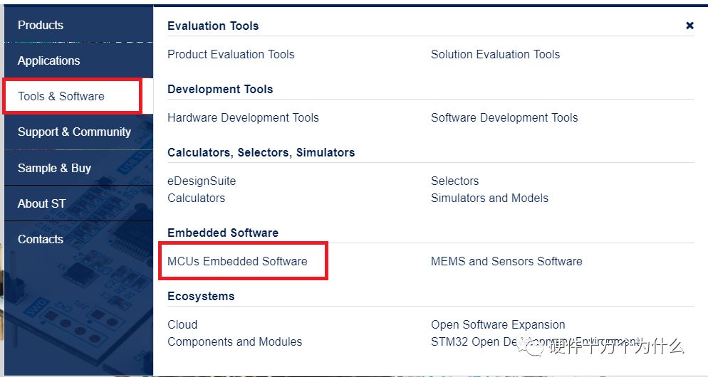
After entering the embedded software page, you can see in the lower left corner For STM32 MCUs
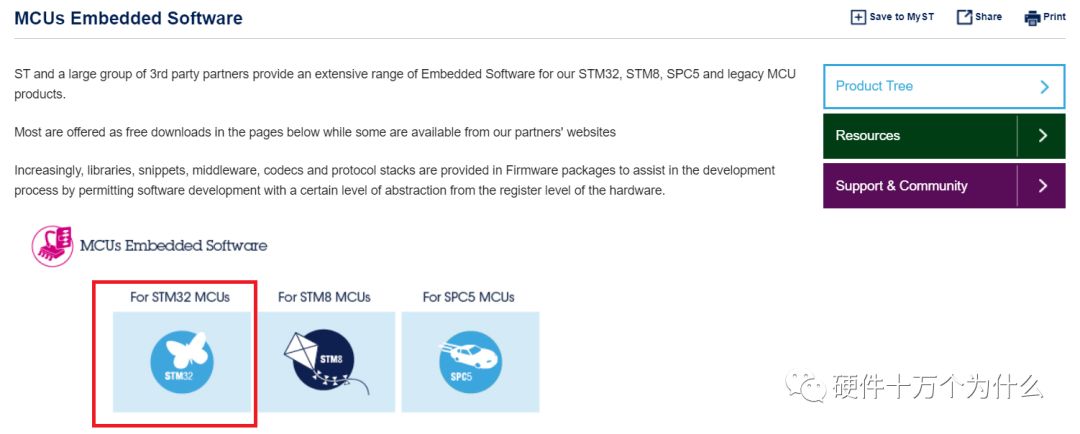
Reminder: If you haven’t registered, you can register an account and log in. You need to log in to download the code.
Once inside, at the bottom of the page, there is a “Download” button. Click it to download.

After clicking “Download”, a compressed package will be downloaded.
The file name is: en.stsw-stm32054.zip
After unzipping, the folder name will be: STM32F10x_StdPeriph_Lib_V3.5.0
You can also paste the link below into your browser for direct download:
https://www.st.com/content/st_com/en/products/embedded-software/mcus-embedded-software/stm32-embedded-software/stm32-standard-peripheral-libraries.html?querycriteria=productId=LN1939%20
Select the corresponding MCU category, for example, we choose F1 for iBox.

Now we have downloaded a complete STM32 official standard peripheral library package.
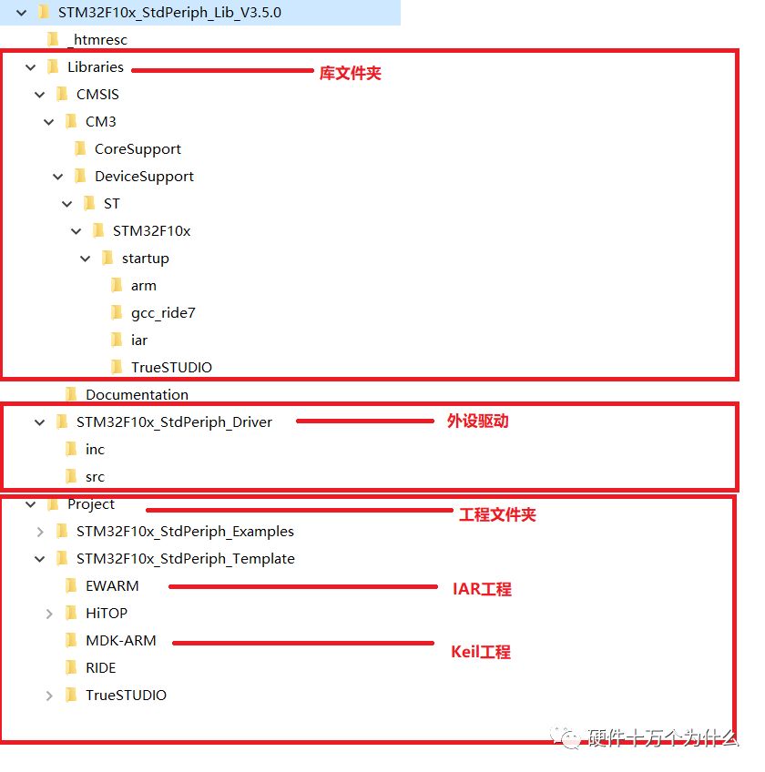
Now we directly enter the MDK-ARM folder and open the Keil project.
The directory is as follows:
STM32F10x_StdPeriph_Lib_V3.5.0\Project\STM32F10x_StdPeriph_Template\MDK-ARM

Double-click to open.
We can try to compile (Build) and download the program (Download).

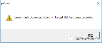
When we click the Download icon, we find that we cannot download because it cannot find your download tool.
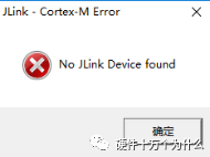
3. Use Jlink for Code Burning
Now, we need to do a few preparations before we can proceed with the code burning:
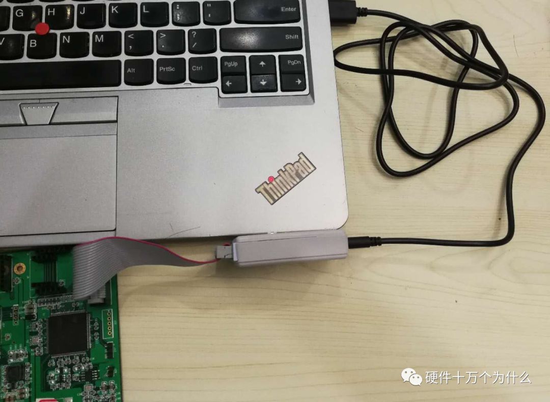
1. Connect Jlink
2. Install Jlink
3. Configure the chip and other burning environments
1. See the picture
2. First, we install Jlink
Download the installation package from the following address:
http://www.hw100k.com/forum.php?mod=viewthread&tid=3507&extra=
Installation notes: None; just click next.
Let’s test if our tool can connect to our MCU.
Click on the start menu: SEGGER- Jlink-FLASH.
Open the JLINK software; it may prompt you to create a project; just create one casually.
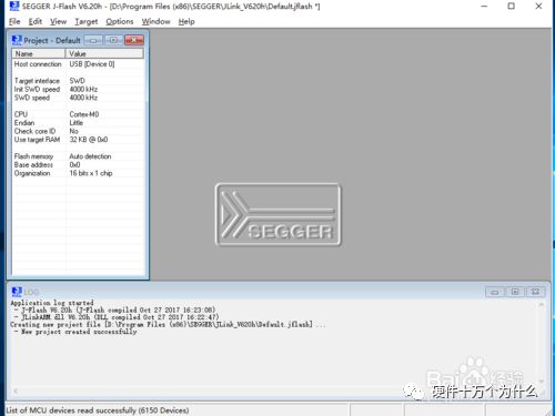
Open the configuration page, click Options->Project settings to enter the configuration page.

The configuration page is shown below, where you can select the microcontroller.
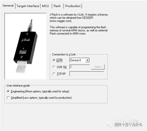
Click on CPU and select the STM32 microcontroller.
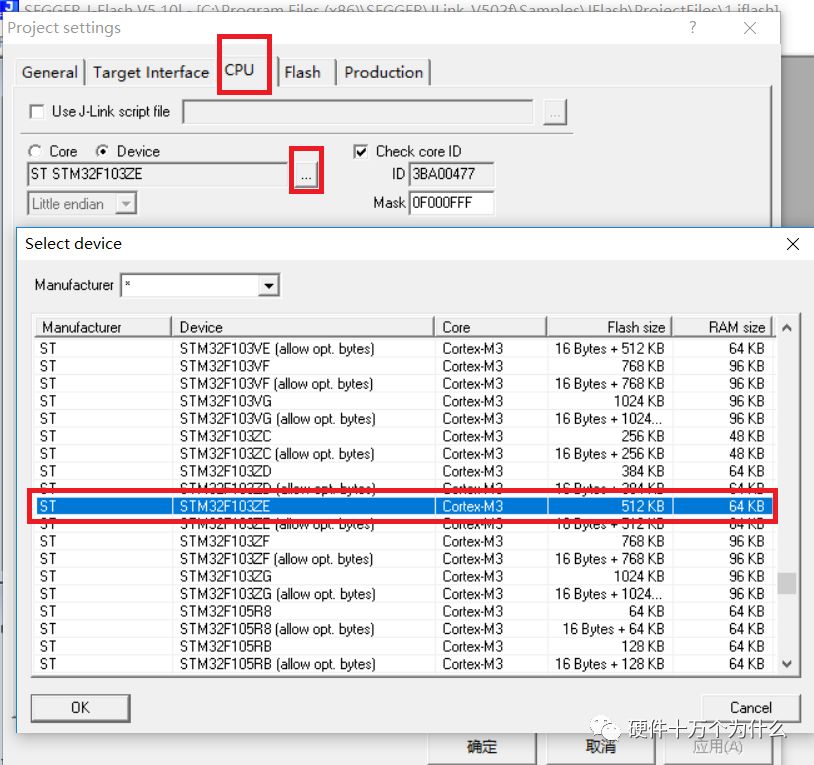
Click on Target, then Connect to link JLINK and the target board.

If the connection is successful, it indicates that both the microcontroller and the Jlink burner are functioning correctly, and the driver is installed successfully.
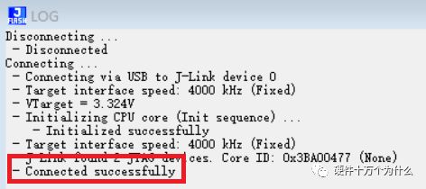
Then we can try to use the Download feature in Keil5; it should work.
(As for how to burn using J-Flash, it will not be covered here.)
3. Don’t rush; we need to configure the chip so that the compilation tool and the computer know the chip model on our circuit board.
Select Flash and then Configure Flash Tools.
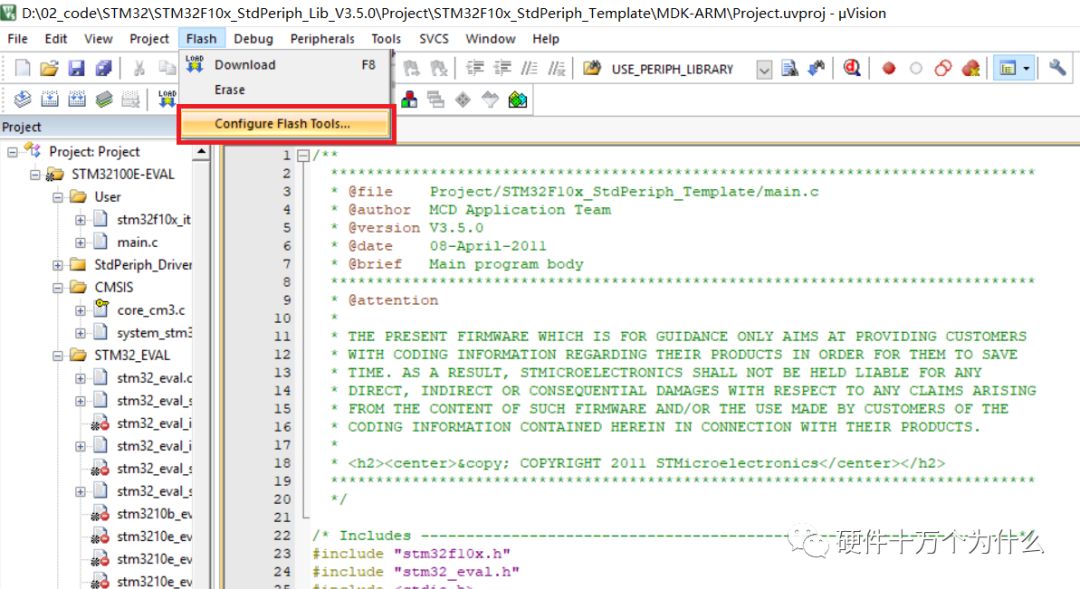
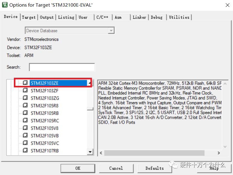
We need to select our chip model in the Device section, as shown below:
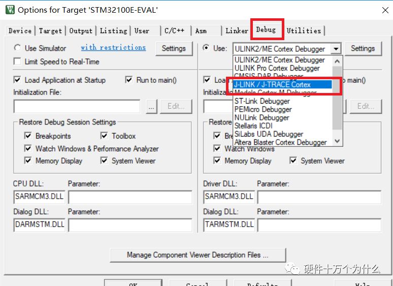
Select Debug and choose Jlink.
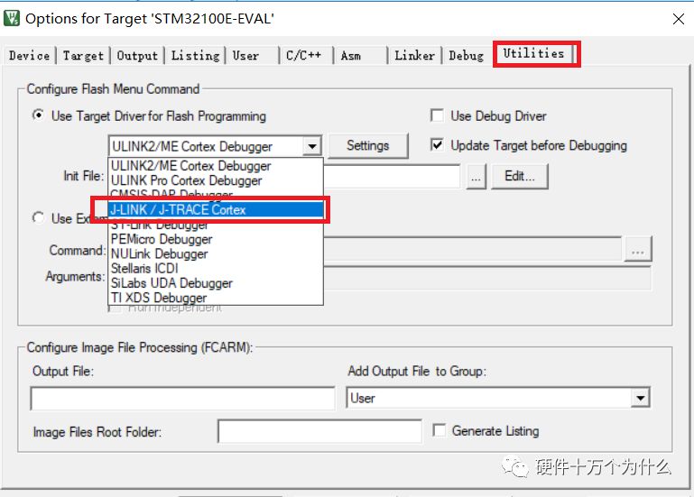
Select Utilities and choose Jlink.
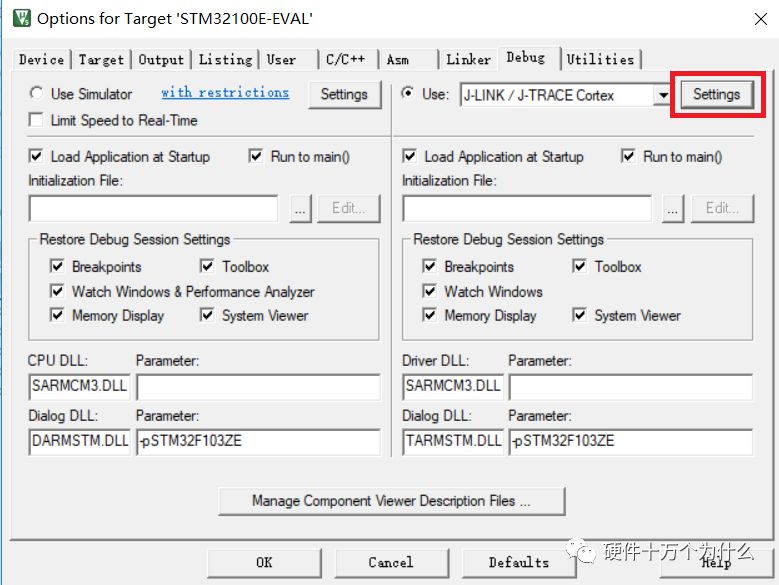
Click on Debug and then the Settings on the right.
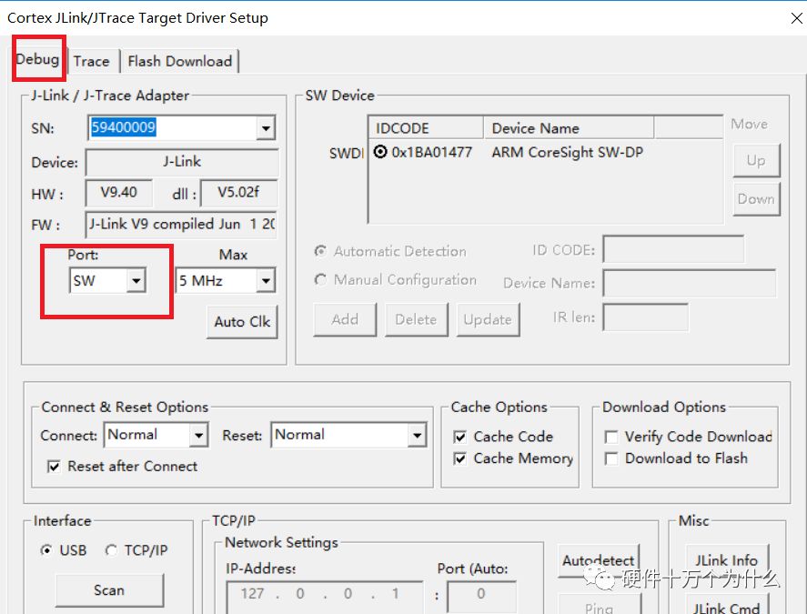
Select the Port in Debug and change JTAG to SW.
Now, we can start downloading.

4. Modify the Source Code to Implement LED Blinking
4.1 Remove Unnecessary Functions
Up to this point, we have not focused on what the official source code actually contains.
Let’s take a look at the main function.
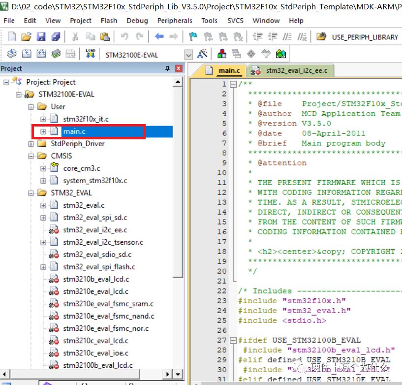
This project is based on the official EVM board from STM32, and this code supports four development boards, hence the four sets of macro definitions. We will temporarily ignore this.
We will delete the code related to UART, LCD, and other functionalities irrelevant to our experimental purpose, keeping only two segments of code: LEDInit and LEDOn.
Based on the function definitions, it is evident that LEDInit is for LED initialization, and LEDOn is for turning the LED on.
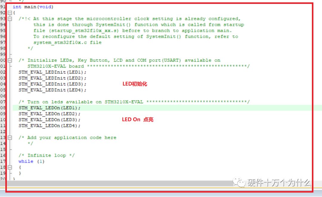
4.2 Study the LED-related Functions and Variables
Let’s examine the STM_EVAL_LEDInit() LED initialization function.
Hover over this function, right-click and select “Go to” to view “STM_EVAL_LEDInit”.
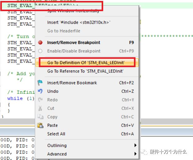
After jumping to it, we can see that this is a standard GPIO initialization function.
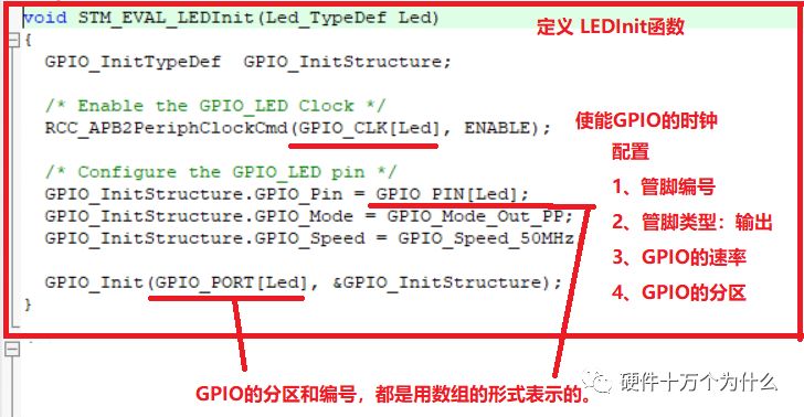
Let’s check how these arrays are defined.

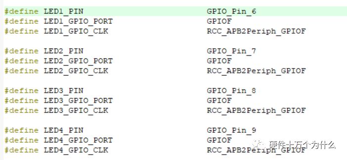
From this, we can see that the original code defines four GPIOs for controlling the LEDs, which are:
F6, F7, F8, F9
Let’s check the schematic to see which GPIOs control the LEDs on the iBox.
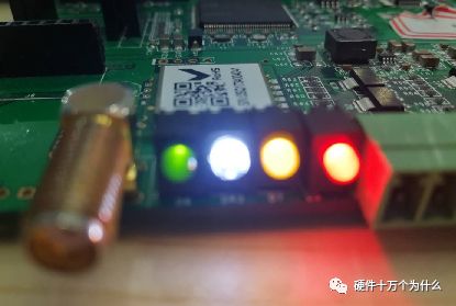
There are four LEDs on the iBox; the red LED is the power indicator and cannot be controlled by GPIO.
We can refer to the schematic:
The positive of the red LED connects to 3V3, and the negative connects to GND through a resistor.
The other three colored LEDs are controlled via GPIO.
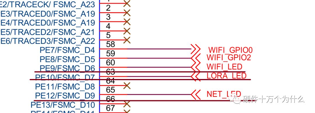
By consulting the MCU pin connections, we can see:
PE9 controls the green light.
PE10 controls the yellow light.
PE12 controls the white light.
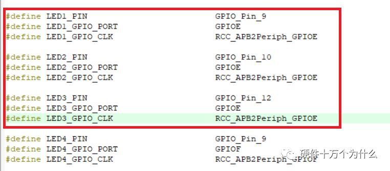
We can modify the pin numbers for LED1, LED2, and LED3 in the code to control the GPIOs for the LEDs on our circuit board.
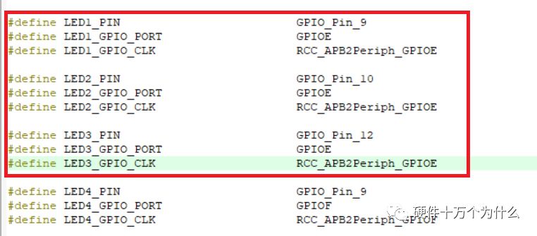
Change the values of LED1 to:
GPIOE
GPIO_Pin_9
RCC_APB2Periph_GPIOE
Using the same method, we modify LED2 and LED3.
After the modifications, our initialization code and the code to control the LEDs correspond to the GPIOs of the LEDs on the iBox.
After studying the initialization code, let’s examine the STM_EVAL_LEDOn function by jumping to its definition.
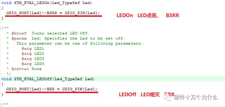
Each GPIO port of STM32 has two special registers, GPIOx_BSRR and GPIOx_BRR. These registers allow you to set or reset the corresponding GPIOx port directly.
The high 16 bits of GPIOx_BSRR correspond to each bit of port x; setting a bit to ‘1’ clears the corresponding bit of port x to ‘0’; the bits set to ‘0’ in the register do not affect the corresponding bits.
The low 16 bits of GPIOx_BSRR also correspond to each bit of port x; setting a bit to ‘1’ in the low 16 bits sets the corresponding port bit to ‘1’; the bits set to ‘0’ in the register do not affect the corresponding bits.
Here, let’s understand simply:
If we want to quickly toggle bit 7 of GPIOE, we can do:
GPIOE->BSRR = 0x80; // Set ‘1’
GPIOE->BRR = 0x80; // Set ‘0’
The library file has already defined the binary corresponding bits for each pin.
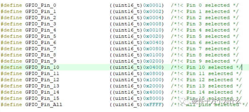
Therefore, if we want the GPIO to be low, we execute:
GPIO_PORT[Led]->BRR = GPIO_PIN[Led];
If we want the GPIO to be high, we execute:
GPIO_PORT[Led]->BSRR = GPIO_PIN[Led];
According to our schematic, when my GPIO is low, the LED lights up; when GPIO is high, the LED is off.
So we need to modify the function as follows:
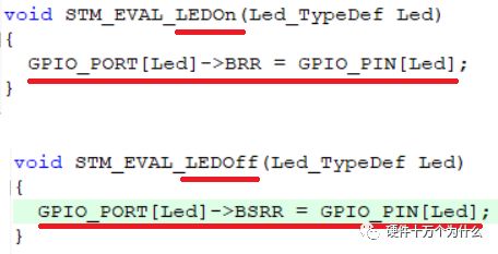
Compile and burn. We can see that the LEDs on our iBox light up as expected.
Thus, our first experiment is complete.
In the next episode, we will create a brand new project using Keil and utilize the official library files, trimming away unnecessary content to create our own first project.
To know what happens next, stay tuned for the next episode.