After reading the above two articles, I believe everyone has a profound understanding of the scheduler and task switching, mastering the operating principles of the scheduler, but there may still be some questions regarding details. For example: how does a task enter the ready state? How is task switching implemented? What is task context, etc.? This article attempts to clarify the implementation process of the scheduler.
Considering that some readers have not participated in the CP Autosar project based on Vector and may not have access to the source code, this article analyzes UCOS-II based on Cortex-M, which is open-source software available online for free. Mastering the UCOS-II scheduler will allow you to easily grasp the Autosar OS scheduler, but note that there are still some differences between the two.
-
SysTick serves as the system clock for the RTOS, with a frequency of 1KHz. -
In the OS environment, when no other exceptions are in an active state, the PendSV exception is used for task switching. -
The processor mode is divided into Thread mode and Handle mode; permissions are categorized as privileged and unprivileged; the stack is divided into MSP and PSP. 
(The above image is from the official ARM documentation)
-
The stack grows downwards (full descending). -
When entering an exception, the processor automatically pushes the values of registers xPSR, PC, LR, R12, R3, R2, R1, R0 onto the stack for saving. Upon exiting, it automatically pops. -
LR is only used to store the return address during the process of calling a sub-function (branch with link instruction); during the exception entry process, LR is pushed onto the stack first, and then the hardware automatically updates the LR value.

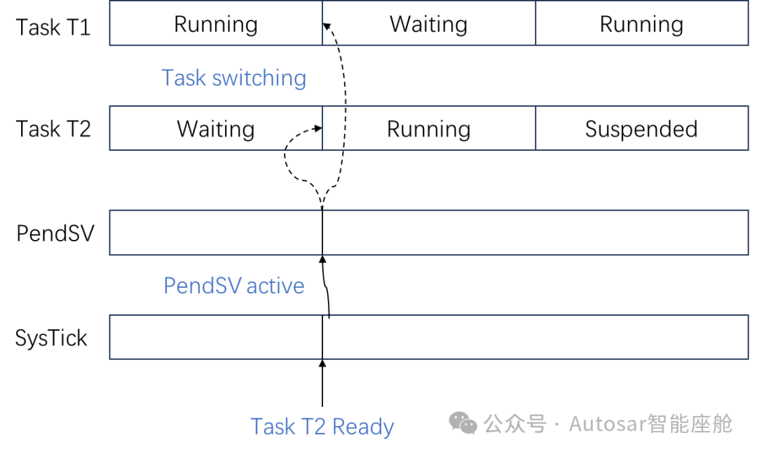
1. SysTick responds to interrupts every 1ms, and within this interrupt, OSTimeTick is called to confirm whether any periodic tasks can enter the ready state. At the 10ms mark, a higher priority task T2 is detected to enter the ready state.
2. Subsequently, a software-triggered PendSV interrupt occurs. In the PendSV interrupt, the stack top of task T1 is obtained, followed by pushing registers R4-R11, R14 onto the stack.
MRS R0, PSP STMFD R0!, {R4-R11, R14} (The code is from UCOS II, same below)
3. Next, the stack top address of task T2 is obtained, and R4-R11, R14 are popped from it.
MOVW R0, #:lower16:OSPrioCur @ OSPrioCur = OSPrioHighRdy;MOVT R0, #:upper16:OSPrioCurMOVW R1, #:lower16:OSPrioHighRdyMOVT R1, #:upper16:OSPrioHighRdyLDRB R2, [R1]STRB R2, [R0]MOVW R1, #:lower16:OSTCBHighRdy @ OSTCBCur = OSTCBHighRdy;MOVT R1, #:upper16:OSTCBHighRdyLDR R2, [R1]STR R2, [R5]ORR LR, R4, #0x04 @ Ensure exception return uses process stackLDR R0, [R2] @ R0 is new process SP; SP = OSTCBHighRdy->OSTCBStkPtr;LDMFD R0!, {R4-R11, R14} @ Restore r4-11, R14 from new process stackMSR PSP, R0 @ Load PSP with new process SP4. Execute the following statement to exit the interrupt. As noted in prerequisite knowledge 5, when exiting an interrupt, the processor automatically pops the stack, meaning that the values of xPSR, PC, LR, R12, R3, R2, R1, R0 saved in task T2’s stack are assigned to the processor’s registers: xPSR, PC, LR, R12, R3, R2, R1, R0. With the PC value from the stack assigned to the PC register, the OS has now executed task T2.
BX LRAutomotive Information Security Collection:
Selected Collection of Automotive Information Security: