This article is my original work. If there are any issues, please point them out in the comments. Thank you!Thanks to iFLYTEK’s Spark Cognitive Model.Comparison and Analysis of Pure ALOHA and Slotted ALOHA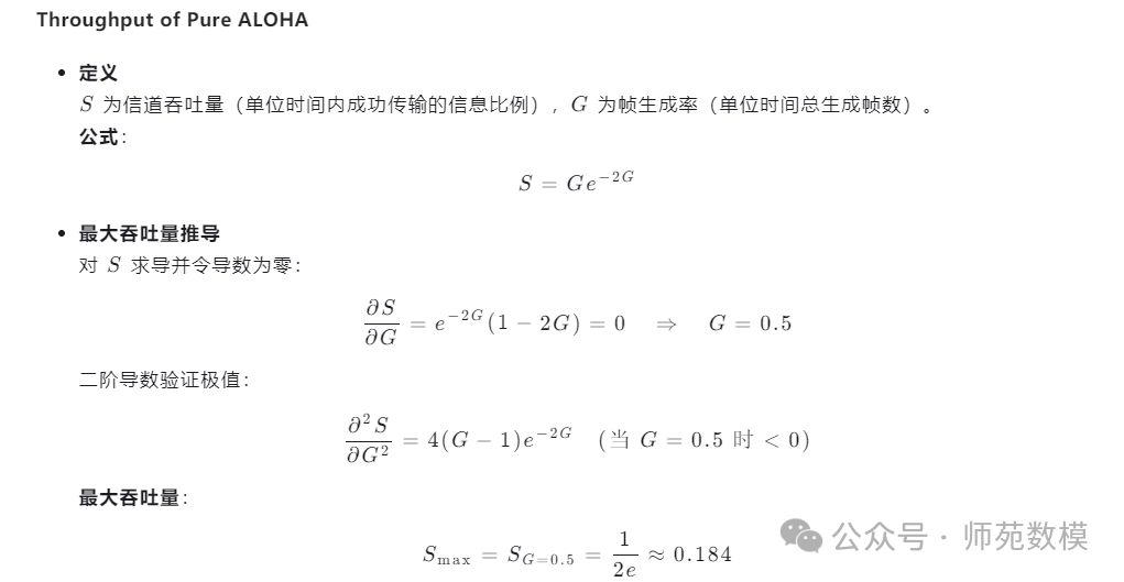


 This section only requires the calculation of these two scenarios.Next, let’s take a look:
Simplified Chinese Version:
-
Difference between RFID and Smart CardsRFID achieves power supply and communication through a contactless magnetic/electromagnetic field, while smart cards require physical contact.
-
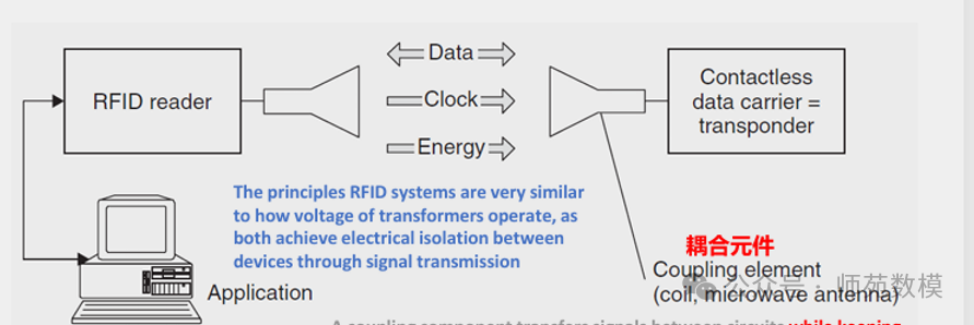
Function of Coupling ComponentsUsing coupling components (such as transformers) to transmit signals between isolated circuits, reducing interference and supporting cross-voltage power supply.
-
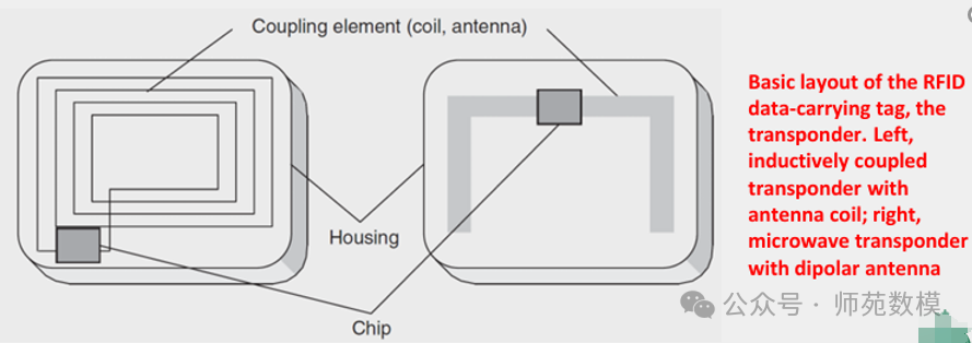
Tag StructureRFID tags contain a radio frequency module, control unit, and coupling components.
-
Communication PrincipleWireless connection between the reader and the tag is achieved through coupling components such as coils/antennas.
-
Responder Types
- Left: Electromagnetic induction type (coil coupling)
- Right: Microwave radiation type (dipole antenna)
Knowledge points about transformers: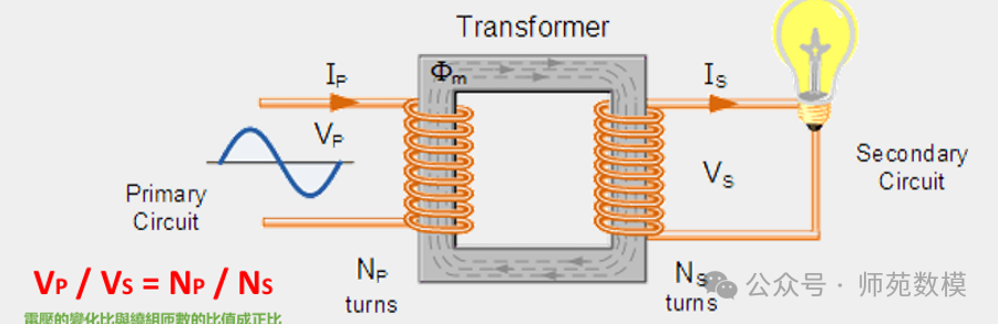
- Transformers transmit electrical energy through two windings that are not directly electrically connected, known as isolation transformers.
- They operate based on the principle of electromagnetic induction: the primary winding converts electrical energy into an alternating magnetic field, and the secondary winding converts the magnetic field energy back into electrical energy.
- The energy conversion process involves two transformations: electrical → magnetic → electrical.
- The primary winding connects to the input power supply, and the secondary winding outputs the required voltage.
- AC power must be used to generate an alternating magnetic field for energy transfer.
- It has electrical isolation characteristics, which can block DC components and ground loops.
Core knowledge points extracted:
-
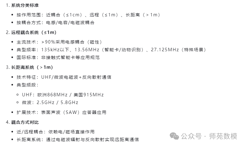
Three Major Distinction Standards of RFID Systems
- Operating frequency (from 135kHz low frequency to 5.8GHz microwave)
- Physical coupling method
- System operating range
Characteristics of Near-Coupling Systems
- Ultra-short operating distance (≤1cm)
- Requires direct contact/tight surface operation
- Dual coupling of electric field + magnetic field
- Very wide frequency adaptability (DC-30MHz can work)
- Can provide high power support (compatible with high-power microprocessors)
Core Principle Advantages
- Can work without relying on electromagnetic field radiation
- Data carrier and reader tightly coupled to improve energy transfer efficiency
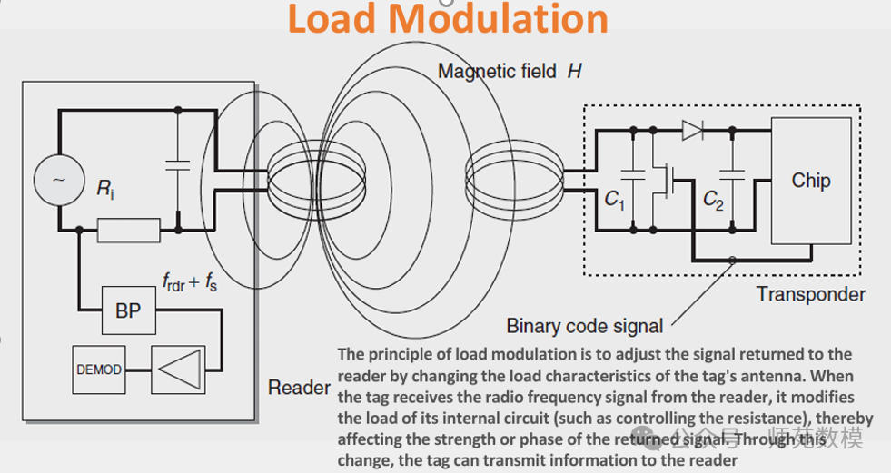 Load Modulation Principle: Resonant responders (tags) change their impedance by drawing energy in the reader’s magnetic field, causing voltage fluctuations in the reader’s antenna; data is transmitted to the reader by controlling impedance changes using voltage signals.
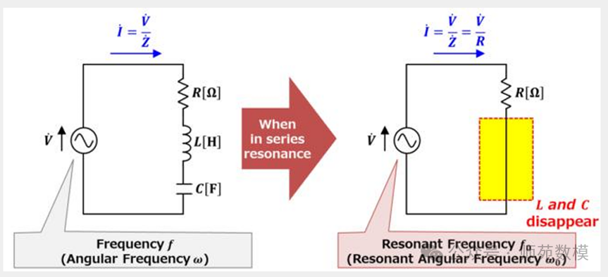
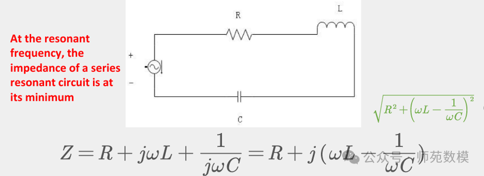
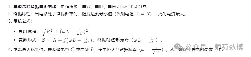
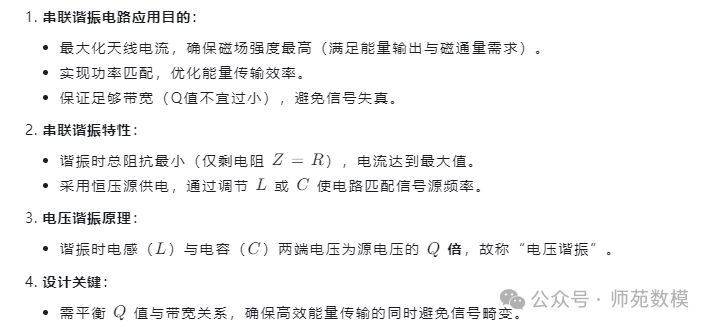
- Function of Series Resonant Circuit: Maximizes antenna current by minimizing total impedance, ensuring the highest magnetic field strength to meet high energy output requirements.
- Necessity of Power Matching: Optimizes energy transfer efficiency, achieving maximum power coupling between the reader’s antenna and the load.
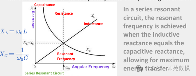
- Balance of Bandwidth and Q Value: Sufficient bandwidth must be ensured to avoid signal distortion, but the Q value should not be too low (selectivity must be considered).
- Resonant Characteristics: When powered by a constant voltage source, the resonant state has minimum impedance and maximum current, directly enhancing magnetic flux generation capability.
- Voltage Resonance Principle: During resonance, the voltage across the inductor (L) and capacitor (C) is Q times the source voltage, hence called “voltage resonance”.
 Please remember these two formulas, as they will be used in the subsequent calculation problems:
 Calculation Problems:
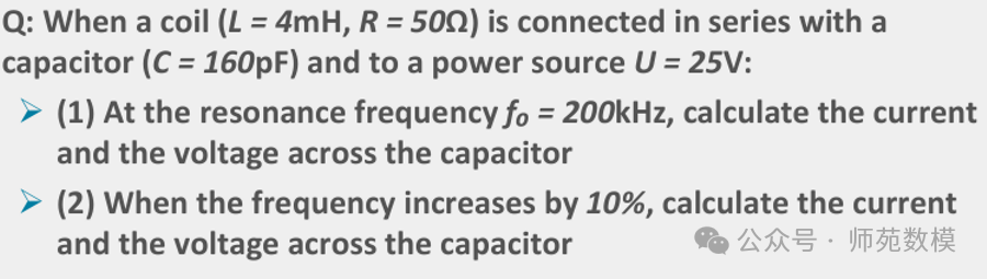


 Please pay attention to the efficiency, which is in scientific notation.


1. Basic Principle of Bipolar-AMI
- Rules:
- Encoding of 1: Alternating positive and negative voltages (polarity alternates).
- Encoding of 0: No signal sent (maintains zero level).
- Characteristics:
- Avoids DC components (DC Balance), suitable for long-distance transmission.
- Solves synchronization issues through polarity alternation (the receiver can recover the clock through level changes).
- Continuous 0s can lead to no signal, potentially causing synchronization loss.
2. Possible Meaning of “Opposite to Bipolar-AMI”
“Opposite” may refer to one of the following two opposite rules:
(1) The polarity of 1 does not alternate, remains fixed
- Rules:
- Encoding of 1: Always uses the same polarity (e.g., fixed positive or negative voltage).
- Encoding of 0: No signal sent.
- Issues:
- Continuous 1s can lead to DC offset (DC Offset), and accumulated charge may damage hardware.
- Lack of level changes makes it difficult for the receiver to recover the clock (synchronization issues).
- Application Scenario: Rarely used, only considered in certain special scenarios (e.g., short distance, low power).
(2) Encoding of 0 is opposite to Bipolar-AMI
- Rules:
- Encoding of 1: Still alternating polarity (same as Bipolar-AMI).
- Encoding of 0: Sends a fixed polarity signal (e.g., fixed positive or negative voltage).
- Characteristics:
- Solves synchronization issues caused by continuous 0s (by filling signals).
- Still maintains DC balance (due to the alternating polarity of 1s, the filling signals of 0s are evenly distributed).
- Practical Application: Similar to HDB3 (High Density Bipolar 3) encoding, used in telephone systems, where violation pulses are inserted during continuous 0s.
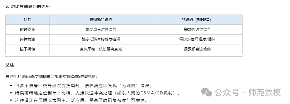
1. Basics of Manchester Encoding
2. Collision Detection Principle
When multiple transponders (e.g., two) transmit different bits simultaneously, signal superposition may lead to the following results:
3. Key Mechanism Analysis
4. Flowchart Interpretation
- Errors occur within a specific bit period, and the system traces back to that bit position.
- The Manchester decoder detects “no transitions” and determines a collision.
- Positive and negative transitions cancel each other out, resulting in the receiver obtaining aconstant level (subcarrier signal).
- Different transponders send different bits (e.g., A sends 1, B sends 0).
- The receiver detects “no transitions” or “illegal signals” and immediately identifies a collision.
- No need to wait for the end of the frame, achievingfast collision detection (compared to non-encoded systems).
- If the transition directions of multiple signals are opposite and time-aligned, the superposition will cancel out the transitions.
- This leads to the received signal havingno change throughout the entire bit period, violating Manchester encoding rules.
- Transition Cancellation:
- Error Trigger:
- Manchester encoding requires each bit to have one transition. If the transition is completely canceled, the receiver detectsno transition, determining it as an error.
- This error is directly related tothe specific bit position, allowing the system to accurately locate the bit where the collision occurred.
- First half period: A’s low level + B’s high level → Intermediate level.
- Second half period: A’s high level + B’s low level → Intermediate level.
- Result: No level transitions throughout the entire bit period, maintaining the intermediate level.
- Transponder A sends logic 1 (low → high transition).
- Transponder B sends logic 0 (high → low transition).
-
Example Scenario:
-
Signal Superposition Effect:
-
Violation State:
- Clock Synchronization: Transitions provide clock signals, and the receiver recovers the clock by detecting transitions.
- Anti-Interference: Zero DC component, suitable for long-distance transmission.
- Logic 1: Low level in the first half period, high level in the second half period (low → high transition).
- Logic 0: High level in the first half period, low level in the second half period (high → low transition).
- Core Rule: Each bit is divided into two halves, encoding data through level transitions:
- Function:
- Multiple transponders transmitting simultaneously:
- Signal Superposition:
- Error Detection:
- Collision Localization:
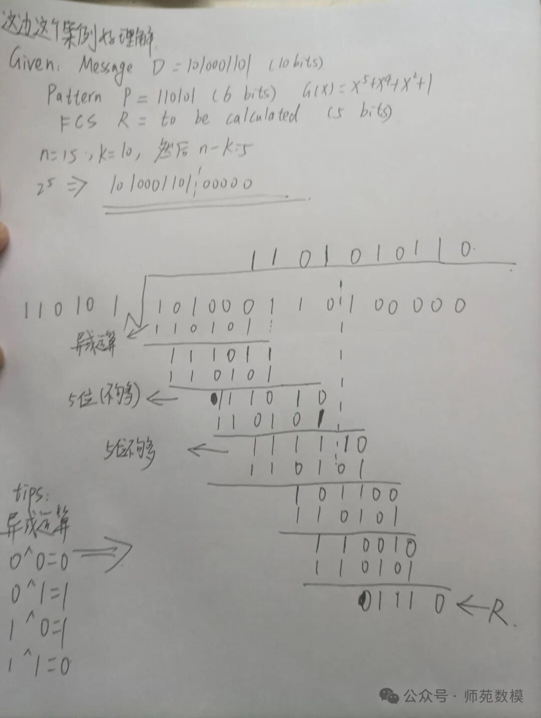
Please refer to the cyclic redundancy check calculation in the PPT; the process is written by me, and I need students to help check it: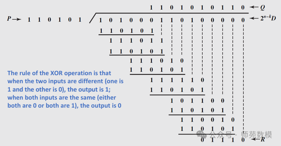

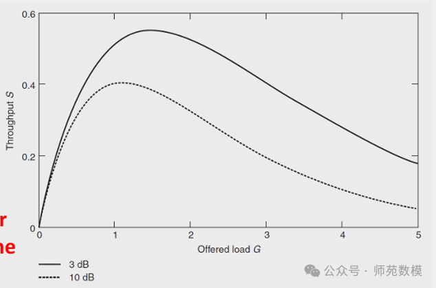
In wireless communication, the Capture Effect affects multi-hop transmission (such as RFID systems or wireless sensor networks) and analyzes throughput behavior under different signal strength thresholds (3 dB and 10 dB). Here are the key interpretations:
1. Core Mechanism of Capture Effect
- Definition: When multiple transponders simultaneously send signals to the reader, the closer transponder will cover the signals of the farther transponders due to higher signal strength, causing the far signals to be “captured” and unable to be correctly parsed.
- Example: If a transponder is close to the reader, its signal strength far exceeds that of other transponders, the reader may only receive the data packet from that strong signal while ignoring the data packets from other weak signals.
2. Role of Thresholds (3 dB and 10 dB)
- Signal Strength Threshold: The 3 dB and 10 dB mentioned in the chart may be the reader’s signal detection thresholds, used to determine which signals can be effectively received.
- 10 dB Threshold: Only transponders with signal strength exceeding 10 dB can be captured by the reader. At this time, weak signals from farther distances (e.g., below 10 dB) will be directly filtered out, reducing the probability of collisions.
- 3 dB Threshold: Allows lower strength signals (e.g., above 3 dB) to be received, but may lead to more transponders competing simultaneously, increasing the probability of collisions.
- Throughput Impact:
- High Threshold (10 dB): Only strong signals are captured, reducing collisions, but may miss data from some far transponders.
- Low Threshold (3 dB): More signals are received, but the strong signal from close distances will suppress the weak signals from farther distances, leading to a decrease in effective throughput.
3. Throughput Behavior Analysis
- Collision and Coverage: When multiple transponders send data simultaneously, the capture effect leads to the following results:
- Close Transponders: Due to strong signals, they successfully transmit data but may cover the signals of other transponders.
- Far Transponders: Due to weak signals, they may be completely ignored under high thresholds or suppressed by strong signals under low thresholds.
- Throughput Variation:
- Low Load Scenario: Few transponders, low collision probability, throughput close to ideal value.
- High Load Scenario: Increased number of transponders, capture effect leads to numerous collisions, and throughput significantly decreases (especially under low thresholds).
4. Practical Application Scenarios
- RFID Warehouse Management: In warehouses, dense RFID tags may lead to data loss due to the capture effect. Adjusting the reader’s sensitivity (e.g., increasing the threshold) can reduce collisions, but coverage range must be balanced.
- Wireless Sensor Networks: In multi-hop transmission, strong signals from close nodes may suppress data transmission from distant nodes, requiring optimization of power control or the use of time division multiple access (TDMA) and other anti-collision mechanisms.

- By dynamically adjusting query prefixes and splitting strategies, achieve collision-free transmission of multiple tags, ensuring each tag is independently selected.
- Repeat the “query-response-split” process until all tags are uniquely identified (e.g., in the example, selecting
<span>1010</span>to choose<span>Tag2</span>, while the remaining tags continue processing). - Based on collision bits and tag responses, dynamically adjust query prefixes (e.g., from
<span>1111111</span>to<span>10</span>), excluding already identified tags (e.g.,<span>11100011</span>), focusing on the common prefix of remaining tags. - When multiple tags respond to the same query, analyze the returned results to determine collision bits (e.g.,
<span>Position 6 is O</span>), splitting the collision nodes into left and right sub-nodes, corresponding to the<span>0</span>and<span>1</span>branches of the collision bit. - Based on a binary tree structure, gradually query prefixes (e.g.,
<span>1111111</span>,<span>10</span>,<span>1010</span>) to split nodes, assigning tags to left and right subtrees, gradually narrowing the search range.
-
Principle of Dynamic Binary Search Algorithm
-
Collision Detection and Splitting Rules
-
Query Prefix Adjustment Strategy
-
Recursive/Iterative Search Process
-
RFID Anti-Collision Applications
1. Core Principle of Dynamic Binary Search
- Layered Splitting Mechanism: Through a binary tree structure, gradually query prefixes (e.g.,
<span>1111111</span>→<span>10</span>→<span>1010</span>), assigning tags to left and right subtrees, narrowing the search range. - Collision Bit Localization: When multiple tags respond to the same query, analyze the returned results (e.g.,
<span>1X1X001X</span>) to determine collision bits (e.g.,<span>Position 6</span>) and split nodes accordingly. - Dynamic Query Adjustment: Based on collision bits and excluded tags, dynamically generate new query prefixes (e.g., adjusting from
<span>1111111</span>to<span>10</span>), skipping processed tags.
2. Key to Avoiding Redundant Data Transmission
- Only Transmit Necessary Prefixes: Each query only needs to send the currently undetermined shortest common prefix (e.g.,
<span>10</span>instead of the full serial number), avoiding repeated transmission of confirmed bits. - Optimize Using Collision Feedback: Directly locate the bits to be split through collision results (e.g.,
<span>Position 6 is O</span>), reducing invalid attempts. - Gradually Exclude Identified Tags: After each round of queries, exclude selected tags (e.g.,
<span>11100011</span>), optimizing subsequent queries only for remaining tags.
3. Advantages of the Algorithm
- Reduce Data Transmission Volume: By dynamically adjusting prefix lengths and skipping redundant bits, significantly reduce the amount of data transmitted each time.
- Improve Efficiency: Compared to traditional full serial number transmission or fixed binary search, dynamic adjustment strategies focus faster on collision tags, accelerating the identification process.
- Applicable to Multi-Tag Scenarios: Especially suitable for the anti-collision needs of numerous tags in RFID systems, achieving collision-free communication through iterative splitting.
4. Application Example Analysis
- Initial Query: Send
<span>1111111</span>, all tags respond, and the collision result is<span>1X1X001X</span>, locating the collision bit<span>6</span>. - First Split: Generate a new query based on the collision bit
<span>10</span>(excluding<span>11100011</span>), remaining tags respond to determine<span>Position 4</span>as<span>0</span>. - Recursive Processing: Continue sending
<span>1010</span>, selecting<span>Tag2</span>, remaining tags enter the next round of splitting until all are identified.
Summary
Dynamic binary search achieves efficient identification of multiple tags through collision detection → prefix adjustment → recursive splitting. Its core lies in dynamically optimizing query prefixes, avoiding redundant transmission, thereby significantly improving the throughput of RFID systems.
Post-Class Exercises:
Q1: Explain how the check digit of the barcode6920152461020 works.Detailed Answer: The check digit of a barcode is usually calculated using a specific algorithm to ensure the correctness of the barcode. For the EAN-13 barcode (such as6920152461020), the calculation steps for the check digit are as follows:
- Add the digits in odd positions from right to left (excluding the check digit).
- Add the digits in even positions and multiply by3.
- Add the two results together.
- Subtract the last digit of the total from10 to get the check digit. For example, for6920152461020:
- Odd positions:0 + 2 + 6 + 1 + 0 + 9 = 18
- Even positions:2 + 1 + 4 + 5 + 2 + 6 = 20 → 20 × 3 = 60
- Total:18 + 60 = 78
- Check digit:10 – (78 % 10) = 2 Therefore, the check digit is2.
Q2: How does a bus use RFID to determine its arrival?Detailed Answer: Buses typically use RFID tags and readers to achieve arrival detection. The specific steps are as follows:
- Install RFID readers at bus stops.
- Equip buses with RFID tags (passive or active).
- When the bus enters the reader’s range, the reader reads the tag information.
- The system determines the bus’s arrival time based on the tag information and updates the arrival information.
Q3: RFID systems rely on coupling components (such as coils or microwave antennas), which help establish a connection between the reader and the tag for non-contact communication. Please explain the working principle of voltage transformers.Detailed Answer: Voltage transformers work based on the principle of electromagnetic induction, specifically as follows:
- Transformers consist of primary and secondary coils, coupled through a core.
- When AC current flows through the primary coil, it generates an alternating magnetic field.
- Voltage is induced in the secondary coil by the alternating magnetic field.
- Output voltage is determined by the turns ratio of the coils.
Q4: The most important distinguishing standards of RFID systems are the operating frequency of the reader, the physical coupling method, and the system range. The operating frequency range of RFID systems is from () long wave to () microwave.A4: 135 kHz, 5.8 GHz.
Q5: How does ohmic load modulation work?Detailed Answer: Ohmic load modulation is a communication method for passive RFID tags, with the following principles:
- The reader sends electromagnetic waves to provide energy for the tag.
- The tag modulates the reflected signal by changing its antenna’s load resistance (e.g., turning on or off the resistance).
- The reader detects changes in the reflected signal to decode the tag information.
Q6: Which parts of the RFID system use series and parallel resonant circuits?Detailed Answer::
- Series Resonant Circuit: Used in tag antennas to improve energy transfer efficiency.
- Parallel Resonant Circuit: Used in reader antennas to enhance signal reception capability.
Q7-Q9: Draw the waveform of the following bit sequences using NRZ-L, NRZI, bipolar AMI, pseudo ternary, Manchester, and differential Manchester encoding techniques:
- 01001100011
- 01011101001
- 10110011
Q10: Given the generating polynomialG(x)=x^{4}+x^{3}+1G(x)=x4+x3+1, please calculate the CRC code for the information sequence10110011.Detailed Answer::
- Represent the information sequence as a polynomial:M(x) = x^7 + x^5 + x^4 + x + 1M(x)=x7+x5+x4+x+1.
- Append4 zeros toM(x)M(x) (because the generating polynomial is4th degree):101100110000.
- Divide the extended sequence byG(x)G(x), obtaining the remainder.
- Append the remainder to the original sequence to obtain theCRC code.
Q11: How do pure/slotted ALOHA and binary/dynamic binary search anti-collision techniques work?Detailed Answer::
- Pure ALOHA: Tags randomly send data, and after a collision, they randomly delay and resend.
- Slotted ALOHA: Time is divided into slots, and tags can only send data at the start of a slot.
- Binary Search: The reader identifies tags by gradually narrowing the range.
- Dynamic Binary Search: Dynamically adjusts the search range to improve efficiency.
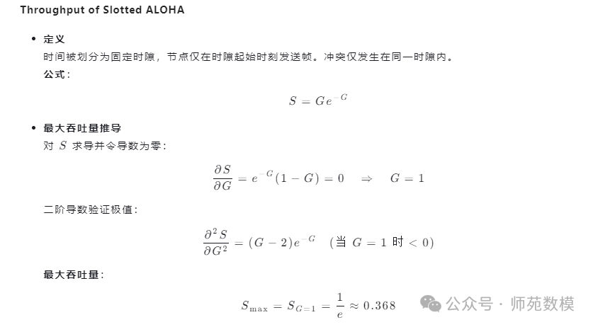
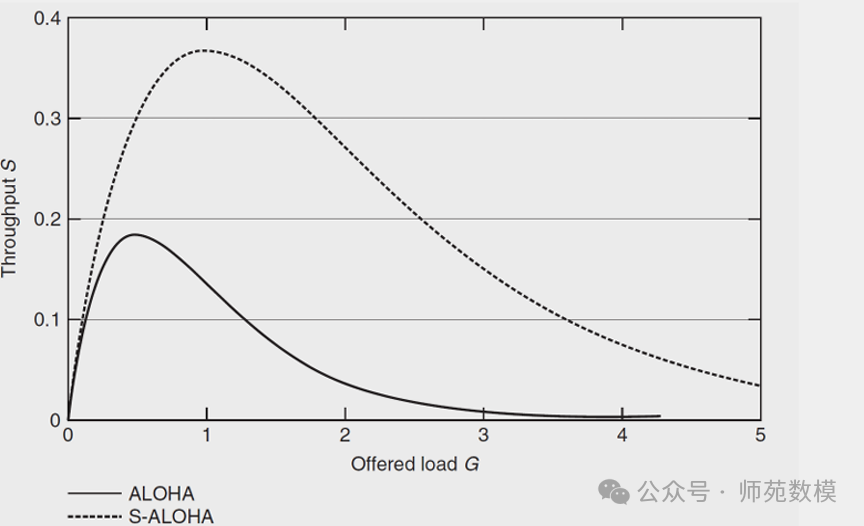
Q12: Please derive the throughput (i.e., successful transmission rate) of pure ALOHA and slotted ALOHA algorithms.Detailed Answer::
- Pure ALOHA: ThroughputS = Ge^{-2G}S=Ge−2G, whereGG is the network load.
- Slotted ALOHA: ThroughputS = Ge^{-G}S=Ge−G.
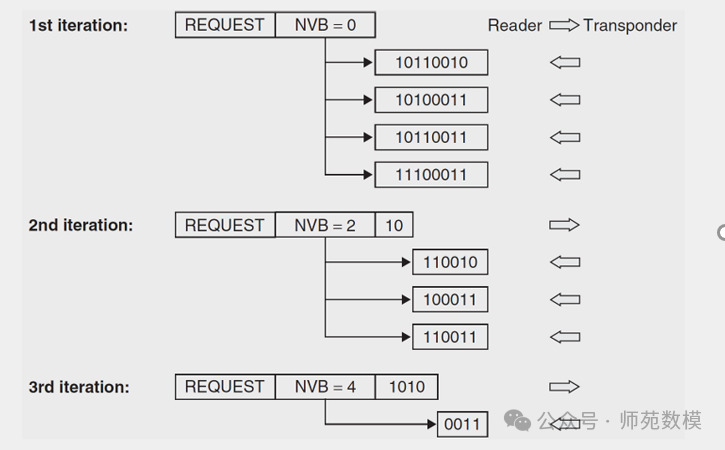
Q13: Since you decided to apply Manchester encoding, you choose to use a binary tree search algorithm to reduce collision effects. Why? Then, assuming the reader has 4 tags (10110010,10100011,10110011,11100011), demonstrate how the algorithm works. If using the dynamic binary search algorithm, please explain how it works.
Detailed Answer: The advantage of Manchester encoding is that it clearly distinguishes bit boundaries, making it easier to detect collision bits.
- Binary Tree Search Algorithm: The reader queries tags bit by bit, narrowing the range based on responses.
- Dynamic Binary Search Algorithm: Dynamically adjusts the search path to reduce the number of queries.
- Review:
- IoT Communication Calculation Problems – Various Calculation Techniques and Principle Verification
- IoT Communication Knowledge Points – Decibel Scale and Power Conversion