Hello, it’s Lao Wu again sharing learning insights! Also, welcome everyone to join the Embedded Hacker WeChat group~ Just add me, and I’ll pull you in.
Purpose:
-
To gain a general understanding of RK3399 Audio functionality from the perspective of driver development.
Environment:
-
NanoPC-T4 / Ubuntu-18.04 / Linux-4.4
Table of Contents:
1. Test Functionality
2. Browse Hardware Information
3. View Driver Layer
4. Application Layer Check Sound Card Information
1. Test Functionality
Playback:
# Check playback devices
$ aplay -l
**** List of PLAYBACK Hardware Devices ****
card 0: realtekrt5651co [realtek,rt5651-codec], device 0: ff880000.i2s-rt5651-aif1 rt5651-aif1-0 []
  Subdevices: 1/1
  Subdevice #0: subdevice #0

# Play wav file on card 0, device 0
$ aplay -D hw:0,0 /root/Music/test.wav
Recording:
# Check record devices
$ arecord -l
**** List of CAPTURE Hardware Devices ****
card 0: realtekrt5651co [realtek,rt5651-codec], device 0: ff880000.i2s-rt5651-aif1 rt5651-aif1-0 []
  Subdevices: 1/1
  Subdevice #0: subdevice #0

# Record from card 0, device 0
$ arecord -D hw:0,0 -f dat filename.wav
2. Browse Hardware Information
1) View Schematic
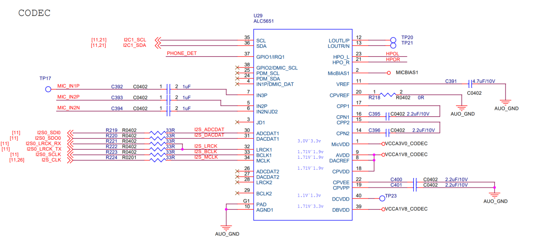
Key Points:
-
Audio Codec Model: Realtek-ALC5651 -
Control: I2C1 -
Data: I2S0 -
Headphone Plug Detection: PHONE_DET -> HP_DET_H -> GPIO4_D3_d -
Recording: MIC_IN2P / MIC_IN2N
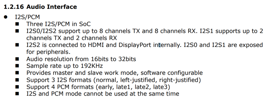
2) View RK3399 Datasheet
Key Points:
3) View RK3399 TRM
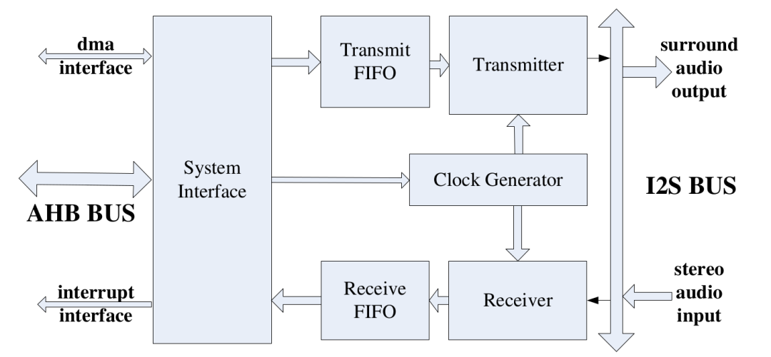
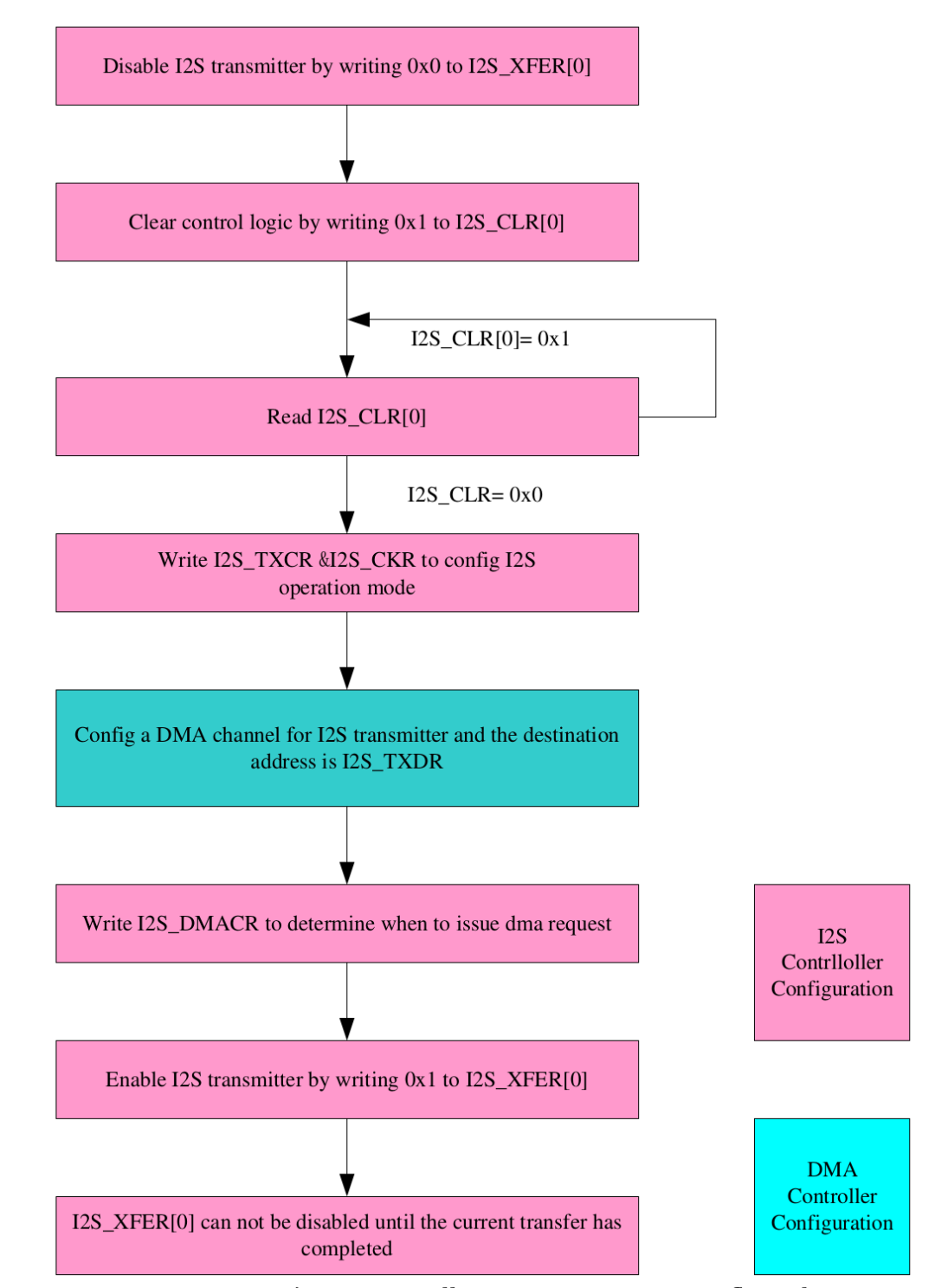
Key Points: (Chapter 22 I2S/PCM Controller):
-
Overview -
Features of I2S/PCM controllers -
Block Diagram -
Function Description -
Master/Slave -
Three Modes of I2S -
Four Modes of PCM -
Register Description, the most important section, must be read in full for deep customization. -
Pin Configuration -
Application Notes
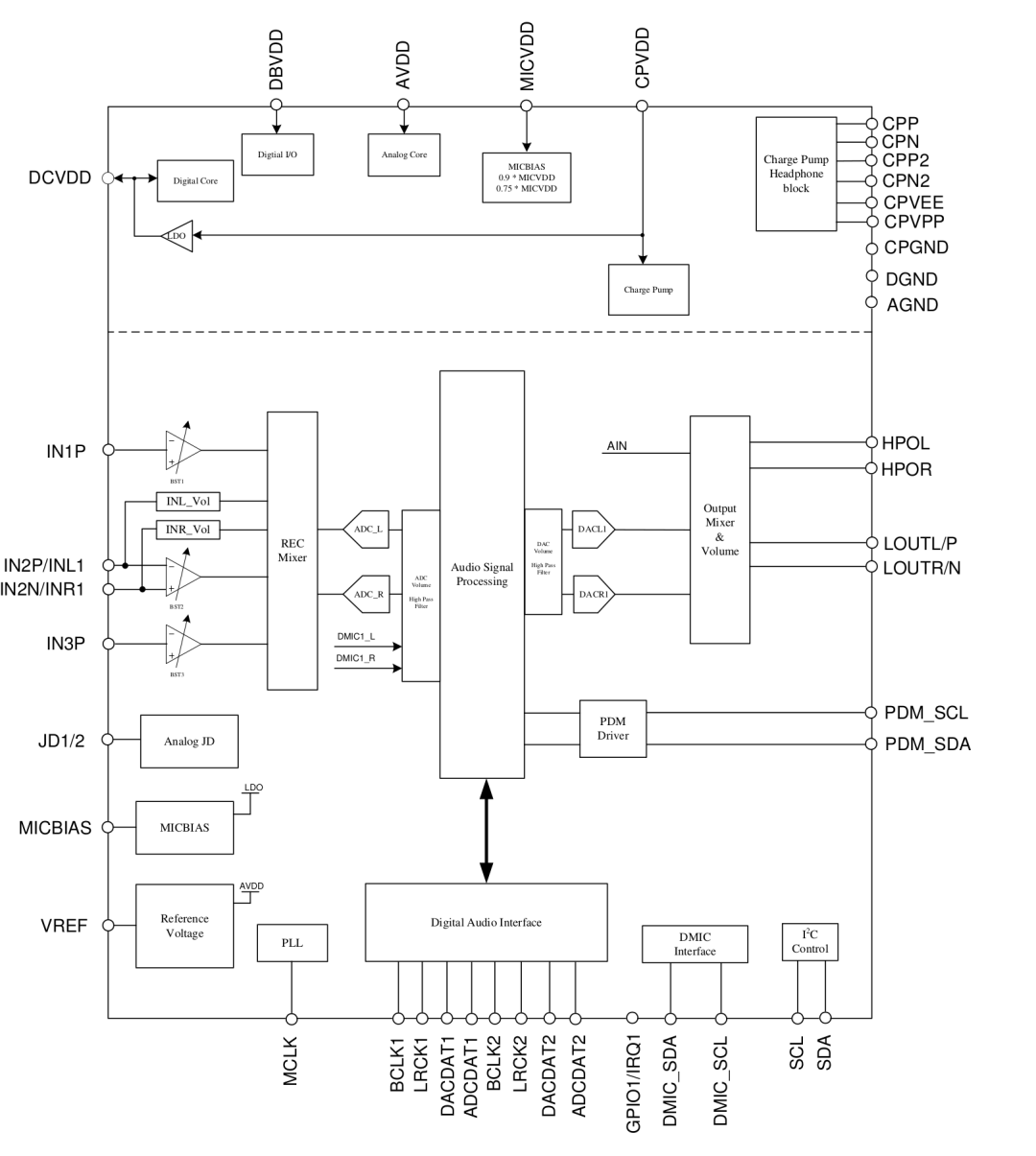
4) View Audio Codec/Realtek-ALC5651 Datasheet
Key Points:
-
2. Features -
4. Function Block and Mixer Path -
Audio Mixer Path -
Digital Mixer Path -
6. Pin Descriptions -
Digital I/O Pins -
Analog I/O Pins -
7. Function Description, the most important section, must be read in full for deep customization. -
8. Registers List
3. View Driver Layer
Reading the following content requires experience in audio driver development, but I will try to provide necessary conceptual explanations.
Soc Audio Simplified Model:
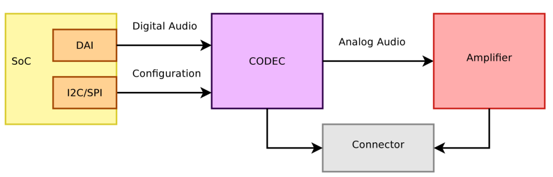
What is DAI?
Digital Audio Interface.
Provides audio data to the codec. Formats are usually AC97, I2S, PCM
What is ASoC?
ALSA System on Chip.
A Linux kernel subsystem created to provide better ALSA support for system-on-chip and portable audio codecs. It allows reusing codec drivers across multiple architectures and provides an API to integrate them with the SoC audio interface.
What does ASoC include?
-
Platform drivers, which provide the capability to configure/enable SoC audio interface (also known as CPU DAI);
-
Codec drivers, which provide the capability to configure/enable the Codec;
-
Machine drivers, which describe how to control CPU DAI and Codec, making them work together;
3.1 View Machine Driver
DT bindings:
arch/arm64/boot/dts/rockchip/rk3399-nanopi4-common.dtsi:
rt5651_card: rt5651-sound {
    status = "okay";
    compatible = "simple-audio-card";
    pinctrl-names = "default";
    pinctrl-0 = <&hp_det>;

    simple-audio-card,name = "realtek,rt5651-codec";
    simple-audio-card,format = "i2s";
    simple-audio-card,mclk-fs = <256>;
    simple-audio-card,hp-det-gpio = <&gpio4 28 GPIO_ACTIVE_HIGH>;

    simple-audio-card,widgets =
        "Microphone", "Mic Jack",
        "Headphone", "Headphone Jack";
    simple-audio-card,routing =
        "Mic Jack", "MICBIAS1",
        "IN1P", "Mic Jack",
        "Headphone Jack", "HPOL",
        "Headphone Jack", "HPOR";

    simple-audio-card,cpu {
        sound-dai = <&i2s0>;
    };
    simple-audio-card,codec {
        sound-dai = <&rt5651>;
    };
};
Here, instead of writing a custom Machine driver, the generic simple-audio-card Machine driver is used.
When the simple-audio-card is sufficient, it is recommended to prioritize using the simple-audio-card framework, as the code will be simpler.
Related Documents and Code:
-
Documentation/devicetree/bindings/sound/simple-card.txt -
Documentation/devicetree/bindings/sound/widgets.txt -
Documentation/sound/alsa/soc/machine.txt -
sound/soc/generic/simple-card.c
What does simple-card.c do?
Although simple-card.c is not specific to a single board, it is still necessary to briefly explain its content.
Since simple-audio-card is a Machine driver, the most important task of a Machine driver is to construct and register struct snd_soc_card, which can be considered as representing a soc sound card:
static int asoc_simple_card_probe() {
    struct snd_soc_dai_link *dai_link;

    [...]
    /* Init snd_soc_card */
    priv->snd_card.owner = THIS_MODULE;
 priv->snd_card.dev = dev;
 dai_link = priv->dai_link;
 priv->snd_card.dai_link = dai_link;
 priv->snd_card.num_links = num_links;

    [...]

    /* Further initialize snd_soc_card based on device tree configuration,
     * including struct snd_soc_dai_link.
     */
    asoc_simple_card_parse_of(np, priv);

    /* Register snd_soc_card */
    devm_snd_soc_register_card(&pdev->dev, &priv->snd_card);
}
There is a relatively important member variable struct snd_soc_dai_link in snd_soc_card, which establishes the connection (link) between CPU DAI and Codec DAI. simple-card.c will initialize snd_soc_dai_link based on the configuration in the device tree.
Further analysis will not be expanded, and the focus will be on the board-related parts.
Analyze Device Tree
1) Specify platform & codec
simple-audio-card,cpu {
    sound-dai = <&i2s0>;
};
simple-audio-card,codec {
    sound-dai = <&rt5651>;
};
Indicates:
-
The platform driver is i2s0; -
The codec driver is rt5651;
2) Define board-related Widgets
simple-audio-card,widgets =
    "Microphone", "Mic Jack",
    "Headphone", "Headphone Jack";
What is a Widget?
-
In ASoC drivers, Widgets describe the functional components of a sound card -
Reference Document: Documentation/sound/alsa/soc/dapm.txt
Two Widgets are defined here:
-
Mic Jack, representing the microphone -
Headphone Jack, representing the 3.5 mm headphone jack
3) Set up board-related Routing
simple-audio-card,routing =
  "Mic Jack", "MICBIAS1",
  "IN1P", "Mic Jack",
  "Headphone Jack", "HPOL",
  "Headphone Jack", "HPOR";
After connecting CPU DAI and Codec DAI, it is also necessary to set the input and output paths of the Codec, which is referred to as Routing.
simple-audio-card,routing serves the purpose of:
A list of the connections between audio components.
Each entry is a pair of strings, the first being the connection’s sink, the second being the connection’s source.
However, I believe that these Widgets and Routing in the device tree are unnecessary, as sufficient Widgets and Routing have already been defined in the Codec driver/rt5651.c to allow the sound card to function properly, which needs to be verified.
3.2 View Platform Driver
DT bindings:
arch/arm64/boot/dts/rockchip/rk3399.dtsi
i2s0: i2s@ff880000 {
  compatible = "rockchip,rk3399-i2s", "rockchip,rk3066-i2s";
  reg = <0x0 0xff880000 0x0 0x1000>;
  rockchip,grf = <&grf>;
  interrupts = <GIC_SPI 39 IRQ_TYPE_LEVEL_HIGH 0>;
  dmas = <&dmac_bus 0>, <&dmac_bus 1>;
  dma-names = "tx", "rx";
  clock-names = "i2s_clk", "i2s_hclk";
  clocks = <&cru SCLK_I2S0_8CH>, <&cru HCLK_I2S0_8CH>;
  resets = <&cru SRST_I2S0_8CH>, <&cru SRST_H_I2S0_8CH>;
  reset-names = "reset-m", "reset-h";
  pinctrl-names = "default";
  pinctrl-0 = <&i2s0_8ch_bus>;
  power-domains = <&power RK3399_PD_SDIOAUDIO>;
  status = "disabled";
};
Related Documents and Code:
-
Documentation/devicetree/bindings/sound/rockchip-i2s.txt -
sound/soc/rockchip/rockchip_i2s.c
What does rockchip_i2s.c do?
ASoC platform drivers are generally written by CPU manufacturers, but understanding their internal implementation is beneficial for grasping the overall ASoC driver framework.
The core task of rockchip_i2s.c is to provide the capability to configure and enable the i2s interface, and its core tasks are as follows.
1) Define a CPU DAI
static struct snd_soc_dai_driver rockchip_i2s_dai = {
 .probe = rockchip_i2s_dai_probe,
 .playback = {
  .stream_name = "Playback",
  .channels_min = 2,
  .channels_max = 8,
  .rates = SNDRV_PCM_RATE_8000_192000,
  ...
 },
 .capture = {
  .stream_name = "Capture",
  .channels_min = 2,
  .channels_max = 2,
  .rates = SNDRV_PCM_RATE_8000_192000,
  ...
 },
 .ops = &rockchip_i2s_dai_ops,
};
A snd_soc_dai_driver represents a CPU DAI, and this structure provides all capabilities of this CPU DAI.
2) Define the operation set for the CPU DAI
static const struct snd_soc_dai_ops rockchip_i2s_dai_ops = {
 .hw_params = rockchip_i2s_hw_params,
 .set_sysclk = rockchip_i2s_set_sysclk,
 .set_fmt = rockchip_i2s_set_fmt,
 .trigger = rockchip_i2s_trigger,
};
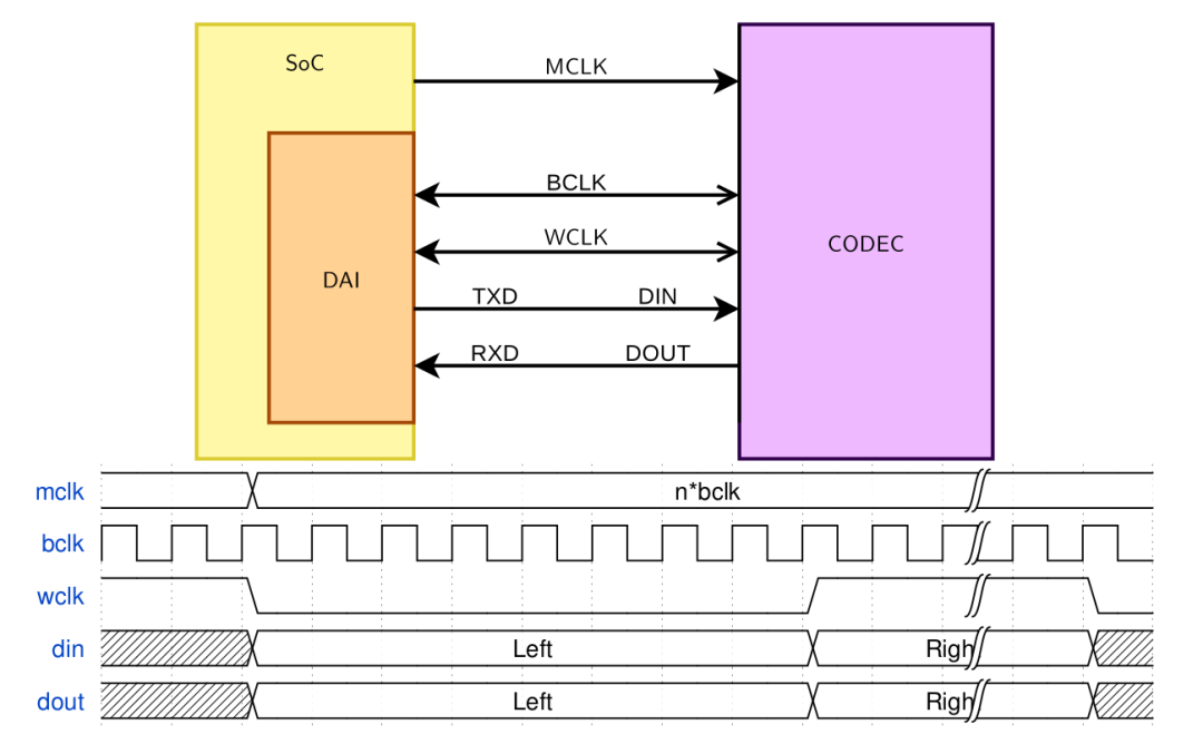
This part is essentially the lowest-level hardware configuration interface for i2s, focusing on clocking / format / channel / master-slave requirements to manipulate registers. These interfaces will be used by the Machine driver to cooperate with the Codec side, and generally, we are most concerned about whether the clock matches, as shown in the simplified model:
3) Register CPU DAI
static int rockchip_i2s_probe(struct platform_device *pdev)
{
    memcpy(soc_dai, &rockchip_i2s_dai, sizeof(*soc_dai));

    ret = devm_snd_soc_register_component(&pdev->dev,
              &rockchip_i2s_component,
              soc_dai, 1);
}
3.3 View Codec Driver
DT bindings:
&i2c1 {
	status = "okay";
	i2c-scl-rising-time-ns = <150>;
	i2c-scl-falling-time-ns = <30>;
	clock-frequency = <200000>;

	rt5651: rt5651@1a {
		#sound-dai-cells = <0>;
		compatible = "rockchip,rt5651";
		reg = <0x1a>;
		clocks = <&cru SCLK_I2S_8CH_OUT>;
		clock-names = "mclk";
		pinctrl-names = "default";
		pinctrl-0 = <&i2s_8ch_mclk>;
		status = "okay";
	};
};
Related Code and Documents:
-
sound/soc/codecs/rt5651.c -
Documentation/sound/alsa/soc/dapm.txt
Key Points in rt5651.c
The driver code for Audio Codec is generally provided by the Codec manufacturer, and understanding its internal implementation is beneficial for customizing based on our needs. Typically, the Audio Codec contains the following key information to represent its internal structure.
1) Define a bunch of snd_kcontrol_new
/* Digital Mixer */
static const struct snd_kcontrol_new rt5651_snd_controls[] = {
 /* Headphone Output Volume */
 SOC_DOUBLE_TLV("HP Playback Volume", RT5651_HP_VOL,
  RT5651_L_VOL_SFT, RT5651_R_VOL_SFT, 39, 1, out_vol_tlv),
 /* OUTPUT Control */
 SOC_DOUBLE_TLV("OUT Playback Volume", RT5651_LOUT_CTRL1,
  RT5651_L_VOL_SFT, RT5651_R_VOL_SFT, 39, 1, out_vol_tlv),
  ...
}

static const struct snd_kcontrol_new rt5616_sto1_adc_l_mix[] = {
 SOC_DAPM_SINGLE("ADC1 Switch", RT5616_STO1_ADC_MIXER,
   RT5616_M_STO1_ADC_L1_SFT, 1, 1),
};
...
snd_kcontrol_new is the raw material for constructing snd_kcontrol.
snd_kcontrol (abbreviated as kcontrol) is a configuration item in the Audio Codec, generally corresponding to a certain field in the register.
2) Define a bunch of Widgets
static const struct snd_soc_dapm_widget rt5616_dapm_widgets[] = {
 SND_SOC_DAPM_SUPPLY("PLL1", RT5616_PWR_ANLG2,
       RT5616_PWR_PLL_BIT, 0, NULL, 0),
  ...

 SND_SOC_DAPM_MIXER("Stereo1 ADC MIXL", SND_SOC_NOPM, 0, 0,
      rt5616_sto1_adc_l_mix,
      ARRAY_SIZE(rt5616_sto1_adc_l_mix)),
  ...
Widgets are functional components in the Audio Codec, and the following diagram makes it easier to understand:
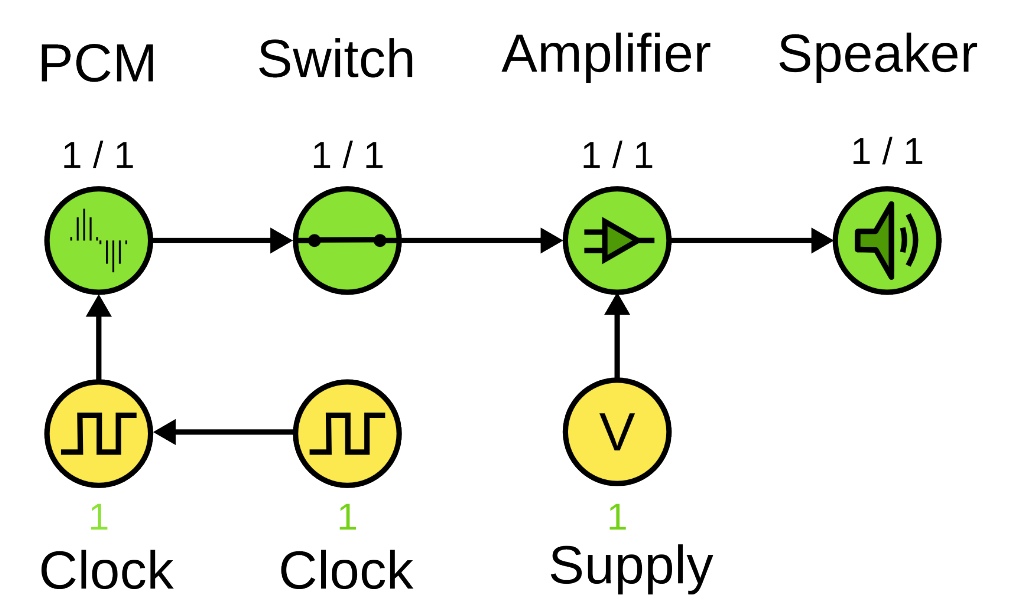
Widget types include:
 o Mixer      - Mixes several analog signals into a single analog signal.
 o Mux        - An analog switch that outputs only one of many inputs.
 o PGA        - A programmable gain amplifier or attenuation widget.
 o ADC        - Analog to Digital Converter
 o DAC        - Digital to Analog Converter
 o Switch     - An analog switch
 o Input      - A codec input pin
 o Output     - A codec output pin
 o Headphone  - Headphone (and optional Jack)
 o Mic        - Mic (and optional Jack)
 o Line       - Line Input/Output (and optional Jack)
 o Speaker    - Speaker
 o Supply     - Power or clock supply widget used by other widgets.
 o Regulator  - External regulator that supplies power to audio components.
 o Clock      - External clock that supplies clock to audio components.
 o AIF IN     - Audio Interface Input (with TDM slot mask).
 o AIF OUT    - Audio Interface Output (with TDM slot mask).
 o Siggen     - Signal Generator.
 o DAI IN     - Digital Audio Interface Input.
 o DAI OUT    - Digital Audio Interface Output.
 o DAI Link   - DAI Link between two DAI structures */
 o Pre        - Special PRE widget (exec before all others)
 o Post       - Special POST widget (exec after all others)
Widgets can be bound to a kcontrol, typically seen with mixer/mux widgets.
3) Define a structure to describe the internal Routing of the Audio Codec: snd_soc_dapm_route
static const struct snd_soc_dapm_route rt5616_dapm_routes[] = {
 {"IN1P", NULL, "LDO"},
 {"IN2P", NULL, "LDO"},
  ...
  {"LOUT L Playback", "Switch", "LOUT MIX"},
 {"LOUT R Playback", "Switch", "LOUT MIX"},
The Route here is somewhat similar to a routing table in a network, where each entry defines a path. By connecting multiple routers’ paths together, a complete audio playback/recording path is formed.
-
The first parameter is the destination; -
The second parameter is the kcontrol that will be used, which can be NULL; -
The third member is the source;
4) Use a structure to summarize all the Codec description information: snd_soc_codec_driver
static struct snd_soc_codec_driver soc_codec_dev_rt5651 = {
 .probe = rt5651_probe,
 .suspend = rt5651_suspend,
 .resume = rt5651_resume,
 .set_bias_level = rt5651_set_bias_level,
 .idle_bias_off = true,
 .controls = rt5651_snd_controls,
 .num_controls = ARRAY_SIZE(rt5651_snd_controls),
 .dapm_widgets = rt5651_dapm_widgets,
 .num_dapm_widgets = ARRAY_SIZE(rt5651_dapm_widgets),
 .dapm_routes = rt5651_dapm_routes,
 .num_dapm_routes = ARRAY_SIZE(rt5651_dapm_routes),
};
snd_soc_codec_driver represents a Codec driver.
5) Register codec driver: snd_soc_register_codec()
static int rt5651_i2c_probe() {
  ...
  ret = snd_soc_register_codec(&i2c->dev, &soc_codec_dev_rt5651,
    rt5651_dai, ARRAY_SIZE(rt5651_dai));
}
Once the codec driver is registered into the system, the system can dynamically determine whether to enable a certain Path inside the Audio Codec; only when the various Routes on the Path are connected and an application is using the sound card does it need to truly power on the Audio Codec.
rt5651_dai is the DAI on the Codec side, which provides the Machine driver with the capability to configure the Codec:
static const struct snd_soc_dai_ops rt5651_aif_dai_ops = {
 .hw_params = rt5651_hw_params,
 .set_fmt = rt5651_set_dai_fmt,
 .set_sysclk = rt5651_set_dai_sysclk,
 .set_pll = rt5651_set_dai_pll,
};

static struct snd_soc_dai_driver rt5651_dai[] = {
 {
  .name = "rt5651-aif1",
  .id = RT5651_AIF1,
  .playback = {
   .stream_name = "AIF1 Playback",
   ...
  },
  .capture = {
   .stream_name = "AIF1 Capture",
   ...
  },
  .ops = &rt5651_aif_dai_ops,
 },
  ...
At this point, the Machine driver has the ability to coordinate control between the Platform side and the Codec side.
4. Application Layer Check Sound Card Information
Check all DAIs:
$ cat /sys/kernel/debug/asoc/dais
i2s-hifi
i2s-hifi
ff870000.spdif
ff8a0000.i2s
ff880000.i2s      // cpu dai
dit-hifi
rt5651-aif2
rt5651-aif1       // codec dai
snd-soc-dummy-dai
Check the Audio Codec registers:
$ cat /sys/kernel/debug/regmap/1-001a/registers
000: 0000
002: 8888
003: c8c8
005: 0000
00d: 0200
...
Check the status of Widgets:
$ cat /sys/devices/platform/rt5651-sound/ff880000.i2s-rt5651-aif1/dapm_widget
I2S1 ASRC: Off
I2S2 ASRC: Off
STO1 DAC ASRC: Off
STO2 DAC ASRC: Off
ADC ASRC: Off
...
Check and configure Kcontrol:
$ tinymix --help
usage: tinymix [options] <command>
options:
 -h, --help        : prints this help message and exits
 -v, --version     : prints this version of tinymix and exits
 -D, --card NUMBER : specifies the card number of the mixer
commands:
 get NAME|ID       : prints the values of a control
 set NAME|ID VALUE : sets the value of a control
 controls          : lists controls of the mixer
 contents          : lists controls of the mixer and their contents
5. References
-
Wei Dongshan Video Tutorial/Audio Special https://www.100ask.net/index
-
Rockchip_RK3399TRM_V1.4_Part1-20170408.pdf
-
ALC5651 DataSheet_V0.92.pdf
-
https://wiki.st.com/stm32mpu/wiki/ALSA_overview
Think About Technology, Also Think About Life
To learn technology, but also to learn how to live.
You and I each have an apple, and if we exchange apples, we still only have one apple. But when you and I each have an idea, if we exchange ideas, we both have two ideas.
Interested in Embedded Systems (Linux, RTOS, OpenWrt, Android) and Open Source Software, follow the public account: Embedded Hacker.
If you find this article valuable, feel free to give a like and a thumbs up.