Many driver frameworks under Linux are quite complex, mostly accumulated over the years by many talented individuals both domestically and internationally.
To learn driver development, it is essential to find your own positioning, grasp the overall picture first, and then appropriately fill in the details. Instead of always trying to delve deeply into the driver framework, thinking from the perspective of a user on how to apply these driver frameworks may yield better results.
Here, I am recording some of my thoughts and learning experiences as a novice, and I welcome corrections.
1. Basic Concepts
1. Two Display Solutions in Linux
Include:
-
FBDEV: Framebuffer Device
-
DRM/KMS: Direct Rendering Manager / Kernel Mode Setting
What are the differences?
-
FBDEV:
-
Traditional display framework; -
Simple, but can only provide the most basic display functions; -
Cannot meet the current display needs of upper-layer applications and underlying hardware; -
DRM/KMS:
-
Currently the mainstream display solution; -
Designed to adapt to increasingly updated display hardware; -
Can support more advanced controls and features in software;
2. Basic Concepts of DRM/KMS
DRM subsystem diagram:
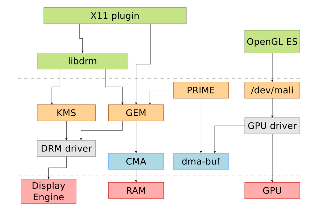
Although DRM/KMS is often used to refer to the entire DRM subsystem, KMS and the DRM driver are only two parts of the entire DRM subsystem.
KMS (Kernel Mode Setting) is one part of the DRM API provided to the application layer, and the application layer generally accesses these APIs through libdrm.
For driver engineers, the focus should be on the DRM driver, which is responsible for enabling the Display engine and can be understood as an enhanced version of FBDEV.
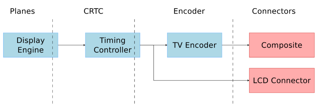
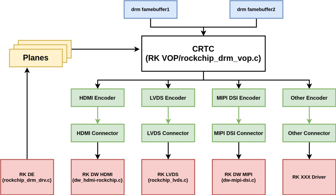
Several important components in KMS:
-
Planes: Layers, for example, corresponding to the win layer of the SOC internal VOP module on the Rockchip platform;
-
CRTC: Display controller, for example, corresponding to the VOP module inside the SOC on the Rockchip platform;
-
Encoder: Output converter, referring to display interfaces such as RGB, LVDS, DSI, eDP, HDMI, CVBS, VGA;
-
Connector: The interface part that interacts between the encoder and the panel;
-
Bridge: Bridge device, generally used for registering conversion chips connected after the encoder, such as DSI2HDMI conversion chips;
-
Panel: Refers to screens in general, an abstraction of various display devices such as LCD, HDMI;
These components form the display pipeline:
3. Viewing DRM/KMS from the Driver Perspective
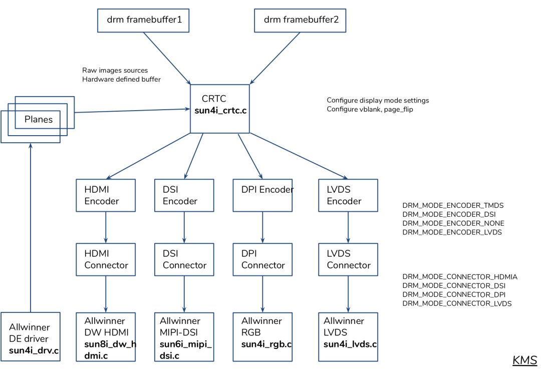
Below is an example using the DRM driver of Allwinner chips for demonstration.
DRM subsystem:
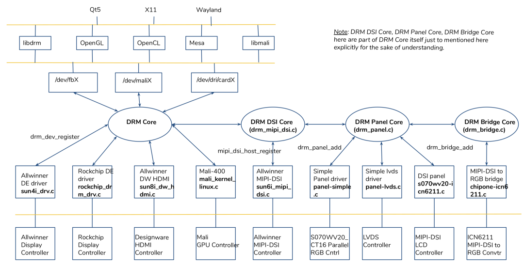
For ease of understanding, the DRM DSI Core / DRM Panel Core / DRM Bridge Core have been separated from the DRM Core, but they actually all belong to the DRM Core.
DRM driver:
2. Understanding Hardware Information
1. Referencing Chip Manuals
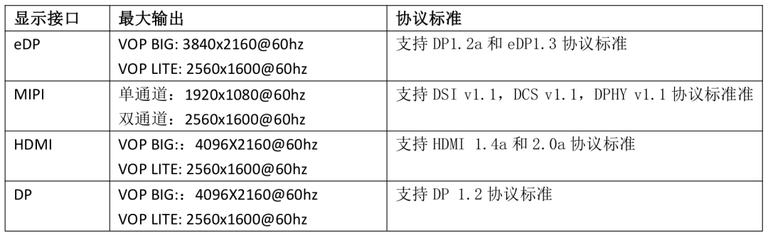
The LCD Controller on the Rockchip platform is called VOP (Video Output Processor), and generally integrates 1-2 VOPs. Only chips that support two VOPs can support dual-screen displays.
RK3399 has 2 VOPs:
-
Video Output Processor (VOP_BIG) -
Video Output Processor (VOP_LIT)
Supported display interfaces:
-
One or Two MIPI-DSI ports -
One eDP port -
One DP port -
One HDMI port
2. Determining the Display Interfaces of the Board
NanoPC T4:
-
LCD Interface: one eDP 1.3 (4 lanes, 10.8Gbps), one or two 4-lane MIPI-DSI; -
DP on Type-C: DisplayPort 1.2 Alt Mode on USB Type-C; -
HDMI: HDMI 2.0a, supporting 4K@60Hz display, supporting HDCP 1.4/2.2;
The responsibility of the driver engineer: to enable various panels connected to the above interfaces according to the needs of upper-layer applications, including enabling a specific screen, dual-screen different displays, dual-screen same displays, etc.
3. Viewing the Device Tree of the Board
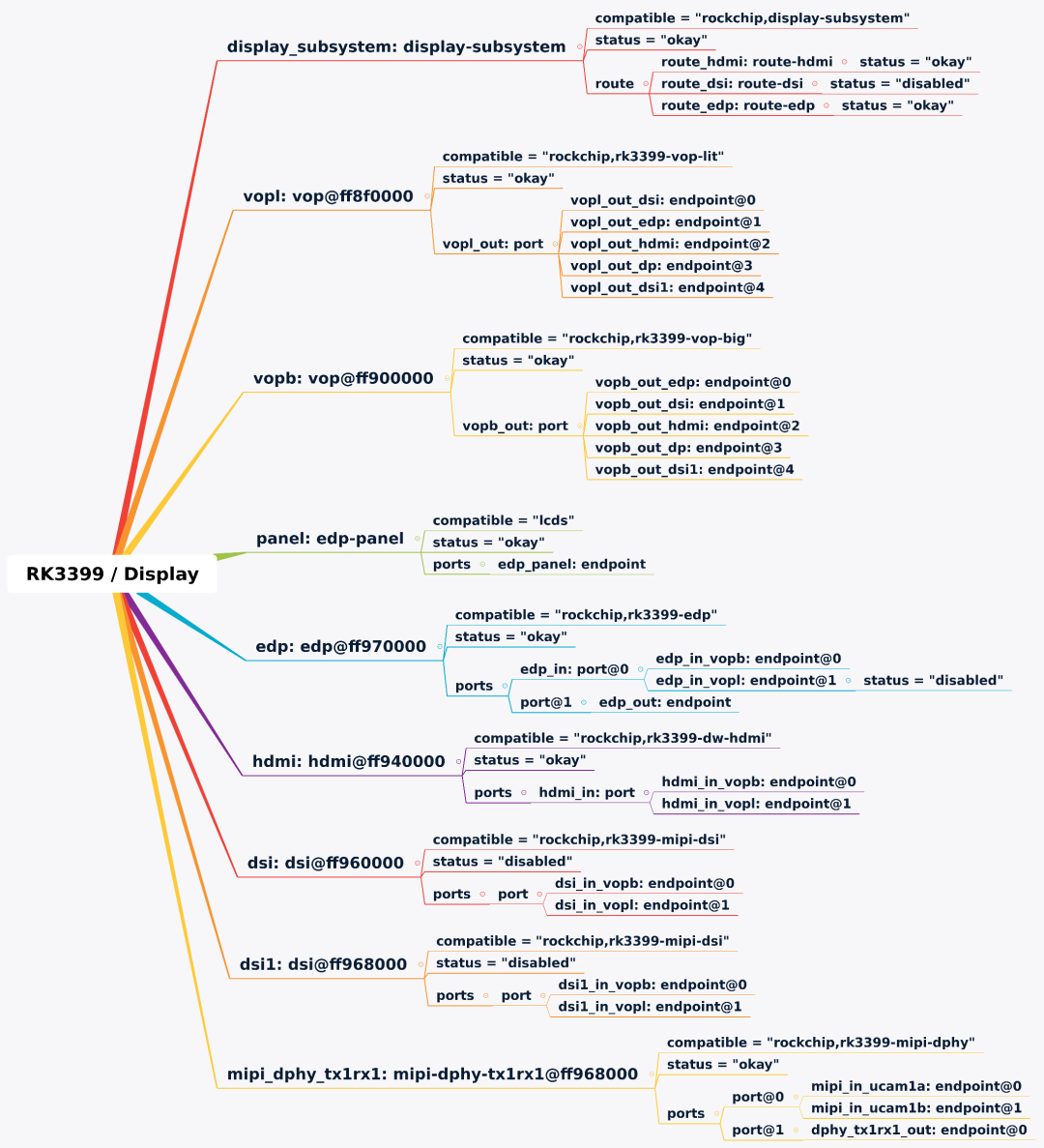
Below is the information related to display in the NanoPC-T4 device tree.
1. Related Nodes and Their Status
2. Functions of Each Node
display-subsystem:
-
Configures Rockchip’s display engine; -
Associates various components (plane / crtc / encoder / connector) through the route table so that the corresponding driver can build the display pipe;
vopl: vop@ff8f0000:
-
Configures VOP little;
-
There are 5 endpoints in the sub-node port named vopl_out_dsi / vopl_out_edp, etc., which are data output endpoints;
-
Each endpoint connects to a remote-endpoint, with VOP’s remote-endpoint connecting to the endpoints of various display encoders, for example, vopl_out_dsi —> dsi_in_vopl;
vopb: vop@ff900000:
-
Omitted
edp: edp@ff970000:
-
Configures the eDP controller, which generally includes base address, interrupts, clock, and sub-node port;
-
2 input endpoints, connecting to VOPL and VOPB;
-
1 output endpoint connects to the eDP panel;
-
There are 3 connections:
-
vopb_out_edp —> edp_in_vopb -
vopl_out_edp —> edp_in_vopl -
edp_out —> edp_panel
panel: edp-panel:
-
Configures a specific eDP screen;
-
There is 1 connection:
-
edp_out —> edp_panel
hdmi: hdmi@ff940000:
-
Configures the HDMI controller, which generally includes pins, base address, interrupts, clock, and sub-node port;
-
There are 2 connections:
-
vopb_out_hdmi —> hdmi_in_vopb -
vopl_out_hdmi —> hdmi_in_vopl
dsi: dsi@ff960000 dsi1: dsi@ff968000:
-
Configures MIPI DSI, similar to eDP / HDMI;
mipi_dphy_tx1rx1: mipi-dphy-tx1rx1@ff968000:
-
Configures MIPI DPHY;
4. Viewing Rockchip’s DRM Driver
1. Driver Paths
| Function | Driver Path |
|---|---|
| DRM master device driver | drivers/gpu/drm/rockchip/rockchip_drm_drv.c |
| Framebuffer driver | drivers/gpu/drm/rockchip/rockchip_drm_fb.c drivers/gpu/drm/rockchip/rockchip_drm_fbdev.c |
| GEM Driver | drivers/gpu/drm/rockchip/rockchip_drm_gem.c |
| VOP Driver | drivers/gpu/drm/rockchip/rockchip_drm_vop.c drivers/gpu/drm/rockchip/rockchip_vop_reg.c |
| LVDS Driver | drivers/gpu/drm/rockchip/rockchip_lvds.c drivers/phy/rockchip/phy-rockchip-inno-video-phy.c |
| RGA Driver | drivers/gpu/drm/rockchip/rockchip_drm_rga.c |
| MIPI Driver | drivers/gpu/drm/rockchip/dw-mipi-dsi.c |
| HDMI Driver | drivers/gpu/drm/rockchip/dw_hdmi-rockchip.c drivers/gpu/drm/bridge/dw-hdmi.c |
| inno HDMI Driver | drivers/gpu/drm/rockchip/inno_hdmi.c drivers/phy/rockchip/phy-rockchip-inno-hdmi-phy.c |
| eDP Driver | drivers/gpu/drm/rockchip/analogix_dp-rockchip.c drivers/gpu/drm/bridge/analogix/analogix_dp_core.c drivers/gpu/drm/bridge/analogix/analogix_dp_reg.c drivers/phy/rockchip/phy-rockchip-dp.c |
| DP Driver | drivers/gpu/drm/rockchip/cdn-dp-core.c drivers/gpu/drm/rockchip/cdn-dp-reg.c |
| TVE/CVBS Driver | drivers/gpu/drm/rockchip/rockchip_drm_tve.c |
2. Probe Process of Rockchip DRM Driver
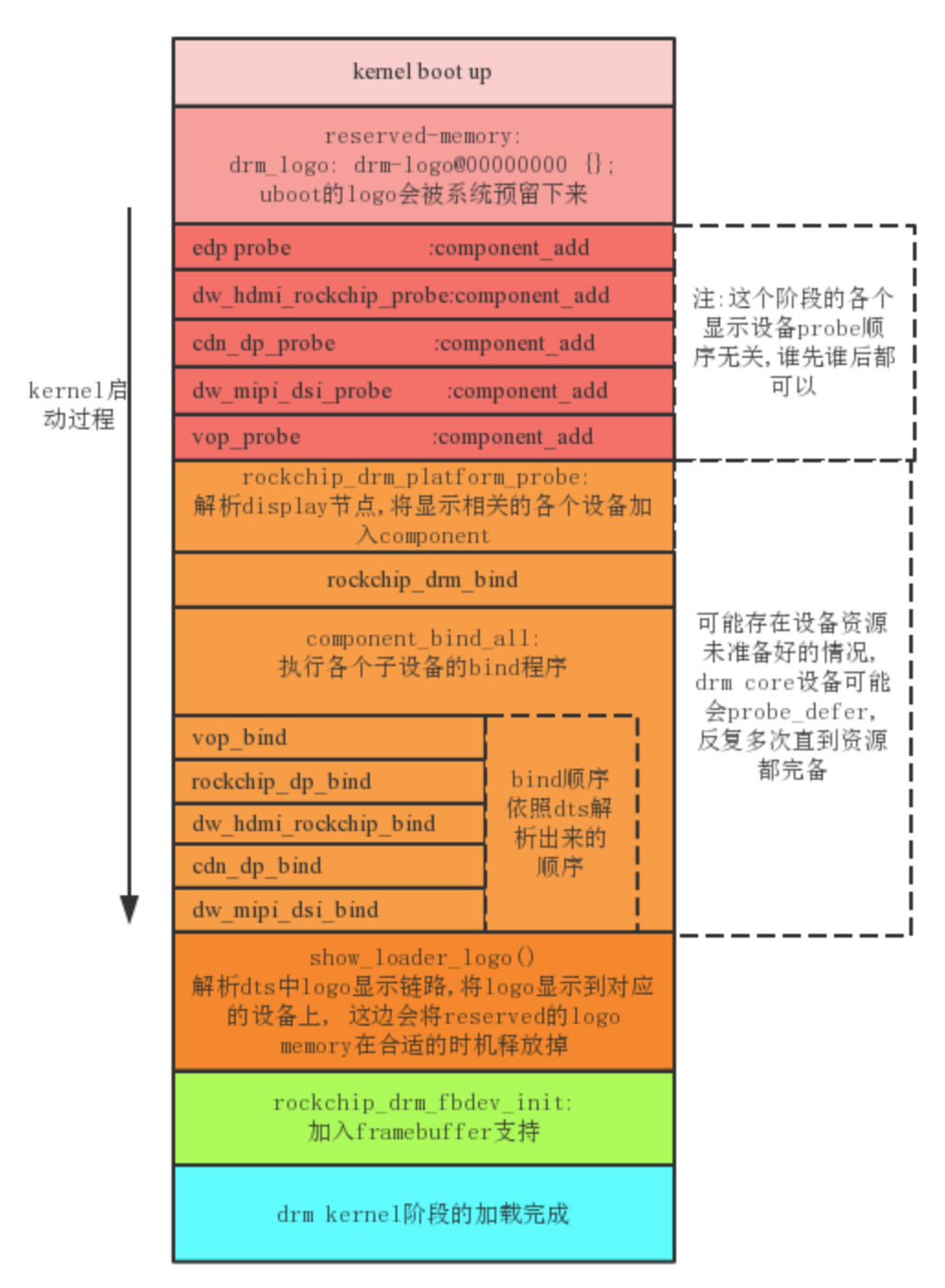
This diagram is provided by Rockchip and is an excellent diagram.
With this diagram, it is equivalent to having a map for source code analysis, which we can refer to for more detailed source code analysis later.
Brief Explanation:
-
Various Encoder drivers and CRTC drivers are probed and then registered into the system via component_add();
-
Rockchip DRM Master device is probed:
-
Registers various Encoder drivers and CRTC drivers through component_match_add() into the component match list;
-
component_master_add_with_match() triggers the bind operations of various Encoder and CRTC components, such as vop_bind(), dw_hdmi_rockchip_bind(), etc.
Binding means associating components in the DRM framework, for example, in the case of vop_bind():
-
VOP Driver corresponds to CRTC driver, CRTC is responsible for connecting Planes and Encoder;
-
vop_create_crtc() -> drm_crtc_init_with_planes() creates the CRTC object and associates it with Planes;
The remaining tasks are peripheral tasks, such as registering the framebuffer to be compatible with FBDEV, displaying logos, etc.
5. Tools for Auxiliary Debugging
1. sysfs
View the current display status; below is the situation where only HDMI is connected:
$ cat /sys/kernel/debug/dri/0/summary
VOP [ff900000.vop]: ACTIVE
    Connector: HDMI-A
        overlay_mode[0] bus_format[100a] output_mode[f] color_space[0]
    Display mode: 1920x1080p60
        clk[148500] real_clk[148500] type[48] flag[5]
        H: 1920 2008 2052 2200
        V: 1080 1084 1089 1125
    win0-0: ACTIVE
        format: XR24 little-endian (0x34325258) SDR[0] color_space[0]
        csc: y2r[0] r2r[0] r2y[0] csc mode[0]
        zpos: 0
        src: pos[0x0] rect[1920x1080]
        dst: pos[0x0] rect[1920x1080]
        buf[0]: addr: 0x0000000000000000 pitch: 7680 offset: 0
    win1-0: DISABLED
    win2-0: DISABLED
    win2-1: DISABLED
    win2-2: DISABLED
    win2-3: DISABLED
    win3-0: DISABLED
    win3-1: DISABLED
    win3-2: DISABLED
    win3-3: DISABLED
    post: sdr2hdr[0] hdr2sdr[0]
    pre : sdr2hdr[0]
    post CSC: r2y[0] y2r[0] CSC mode[1]
VOP [ff8f0000.vop]: DISABLED
View a specific display device:
$ ls /sys/class/drm/
card0  card0-DP-1  card0-eDP-1  card0-HDMI-A-1  controlD64  renderD128  version
2. Adjusting DRM Log Level
/sys/module/drm/parameters/debugThe meaning of each bit in debug:
-
Bit 0: enable CORE messages (drm core code) -
Bit 1: enable DRIVER messages (drm controller code) -
Bit 2: enable KMS messages (modesetting code) -
Bit 3: enable PRIME messages (prime code) -
Bit 4: enable ATOMIC messages (atomic code) -
Bit 5: enable VBL messages (vblank code) (int)
3. libdrm/modetest
modetest is a test program provided by libdrm, which can query the support status of display devices, perform basic display tests, and set display modes.
$ git clone https://gitlab.freedesktop.org/mesa/drm
$ apt-get install meson
$ meson builddir/
$ ninja -C builddir/ install
$ ./builddir/tests/modetest/modetest -h
usage: ./builddir/tests/modetest/modetest [-acDdefMPpsCvrw]
...
6. References
-
Linux kernel Documentation
-
Rockchip RK3399 Datasheet V2.1-20200323.pdf
-
Rockchip_Introduction_DRM_Integration_Helper_CN.pdf
-
Rockchip DRM Display Driver Development Guide V1.0.pdf
-
Rockchip_Developer_Guide_DRM_Panel_Porting_CN.pdf
-
The DRM/KMS subsystem from a newbie’s point of view.pdf
Thinking About Technology and Life
To learn technology, you must also learn how to live.
If you and I each have an apple, and we exchange apples, we still only have one apple each. But when you and I each have an idea, and we exchange ideas, we both have two ideas.
Interested in embedded systems (Linux, RTOS, OpenWrt, Android) and open-source software, follow the public account: Embedded Hacker.
If you find the article valuable, please give it a look and a like.