“This article focuses on the GPTIMER of the ESP32-S3, introducing its two groups of four 54-bit general-purpose timers, their composition and characteristics, and comparing them with the SYSTIMER. It explains the working principles based on clock division and counting comparison, demonstrating its applications in precise timing scenarios through LED toggling examples in free-running, one-shot, and periodic alarm modes.”
01
—
Introduction to GPTIMER
1. Quantity:
The ESP32-S3 provides two identical timer groups, referred to as TIMG0 and TIMG1.
Each timer group contains:
-
Two 54-bit general-purpose timers (T0, T1);;
-
One 32-bit main system watchdog timer (MWDT);;
-
Thus, the chip has a total of four independently programmable general-purpose timers.
2. Differences between GPTIMER and SYSTIMER:
|
Dimension |
Timer Group (TIMG) |
System Timer (SYSTIMER) |
|
Domain |
Peripheral Bus (APB) |
Inside CPU Core |
|
Instance Count |
2 groups × 2 timers = 4 |
1 group, containing 2 counters (UNIT0/1) |
|
Counting Bit Width |
54 bits |
52 bits |
|
Clock Source |
APB_CLK (80 MHz typical) |
XTAL_CLK divided to 16 MHz |
|
Interrupt Lines |
2 per group (1 for T0/T1 each) |
3 comparator interrupts |
|
Output to GPIO |
Can map any pin through GPIO matrix |
No direct output |
|
Typical Uses |
Cyclic sampling, PWM, precise delays |
Operating system ticks, sleep wake-up compensation |
3. Application Scenarios
-
Microsecond-level precise timing interrupts;
-
Software PWM (toggling GPIO within interrupt service routines);
-
Pulse counting or frequency measurement;
-
Low-power wake-up source (in conjunction with RTC).
4. Features
-
16-bit prescaler, division factor 2–65536;;
-
54-bit time base counter, can increment or decrement;;
-
Level-triggered interrupts, require software clearing..
5. Operating Modes
-
Free-running: The counter runs continuously, resets to zero after overflow and continues;
-
One-shot alarm: The counter stops when it reaches the alarm value, generating a single interrupt;
-
Periodic alarm: The counter automatically reloads the initial value and continues counting after reaching the alarm value, generating periodic interrupts.
02
—
Principle of GPTIMER
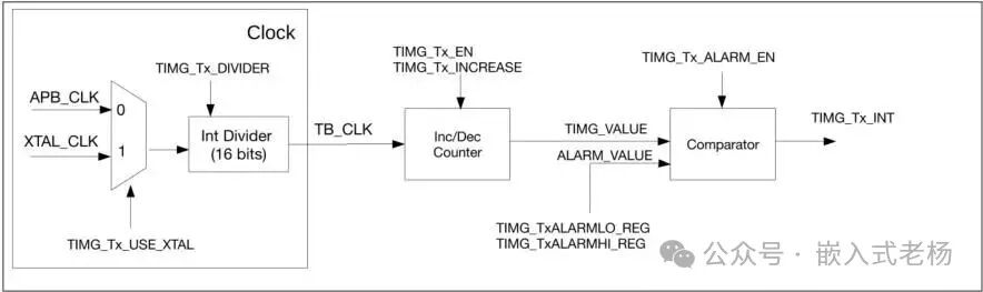
1. Functional Block Diagram
-
Clock (Clock Module): Includes clock source selection (selecting APB_CLK or XTAL_CLK via TIMG_Tx_USE_XTAL) and a 16-bit integer divider (Int Divider, configured by TIMG_Tx_DIVIDER) to provide the timer with a divided reference clock TB_CLK.
-
Inc/Dec Counter: Driven by TB_CLK, counts based on TIMG_Tx_INCREASE to determine counting direction (increment or decrement), and counts when TIMG_Tx_EN is enabled, outputting the current count value TIMG_VALUE.
-
Comparator: Receives the counter output TIMG_VALUE and the ALARM_VALUE configured by TIMG_TxALARMLO_REG, TIMG_TxALARMHI_REG. When both match and TIMG_Tx_ALARM_EN is enabled, it generates the TIMG_Tx_INT interrupt signal.
2. Working Principle
The clock module first selects APB_CLK or XTAL_CLK and obtains the reference clock TB_CLK through the 16-bit divider; the Inc/Dec counter counts in the TIMG_Tx_INCREASE direction (increment/decrement) under TB_CLK drive and TIMG_Tx_EN enablement, outputting TIMG_VALUE; the comparator continuously compares TIMG_VALUE with the ALARM_VALUE configured by the TIMG_TxALARM registers, triggering the TIMG_Tx_INT interrupt when matched and TIMG_Tx_ALARM_EN is enabled, thus achieving timing functionality, supporting one-time or periodic timing.
03
—
Programming Case
1. Function:
GPIO1 drives an LED to toggle every 500ms.
2. Programming Steps for Each Mode:
Unified Process:
-
Install drivers (create project, automatically implemented);
-
Create timer handle gptimer_new_timer();
-
Set clock source, resolution, counting direction;
-
Register event callback gptimer_register_event_callbacks();
-
Enable timer gptimer_enable();
-
Start timer gptimer_start();
①. Free-running Mode (Main Loop Software Polling)
In the “Free-running Mode” example, no hardware features of the ESP32-S3 timer group (TIMG) are used, relying entirely on software polling (esp_timer_get_time()) for timing control, thus the above unified process related to the timer group (TIMG) hardware does not need to be executed.
/* File: timg_free_run.c */#include "driver/gpio.h"#include "esp_timer.h"#include "freertos/FreeRTOS.h"#include "freertos/task.h"
#define LED_GPIO  GPIO_NUM_1
void app_main(void){    gpio_reset_pin(LED_GPIO);    gpio_set_direction(LED_GPIO, GPIO_MODE_OUTPUT);
    int level = 0;    int64_t last_us = esp_timer_get_time();    while (true) {        int64_t now_us = esp_timer_get_time();        if (now_us - last_us >= 500000) {   // 500 ms            level = !level;            gpio_set_level(LED_GPIO, level);            last_us = now_us;        }        vTaskDelay(pdMS_TO_TICKS(10));    }}
②. One-shot Alarm Mode
/* File: timg_one_shot.c */#include "driver/gpio.h"#include "driver/gptimer.h"#include "freertos/FreeRTOS.h"#include "freertos/semphr.h"
#define LED_GPIO  GPIO_NUM_1static SemaphoreHandle_t one_shot_sem;
static bool IRAM_ATTR timer_one_shot_cb(gptimer_handle_t timer,                                        const gptimer_alarm_event_data_t *edata,                                        void *user_ctx){    BaseType_t high_task_awoken = pdFALSE;    xSemaphoreGiveFromISR(one_shot_sem, &high_task_awoken);    return high_task_awoken == pdTRUE;}
void app_main(void){    gpio_reset_pin(LED_GPIO);    gpio_set_direction(LED_GPIO, GPIO_MODE_OUTPUT);
    one_shot_sem = xSemaphoreCreateBinary();    gptimer_handle_t timer = NULL;    gptimer_config_t cfg = {        .clk_src = GPTIMER_CLK_SRC_APB,   // 80 MHz        .direction = GPTIMER_COUNT_UP,        .resolution_hz = 1 * 1000 * 1000, // 1 µs/tick    };    gptimer_new_timer(&cfg, &timer);
    gptimer_event_callbacks_t cbs = { .on_alarm = timer_one_shot_cb };    gptimer_register_event_callbacks(timer, &cbs, NULL);    gptimer_enable(timer);
    gptimer_alarm_config_t alarm_cfg = {        .alarm_count = 500 * 1000, // 500 ms        .reload_count = 0,        .flags.auto_reload_on_alarm = false,    };
    int level = 0;    while (true) {        gpio_set_level(LED_GPIO, level);        level = !level;
        gptimer_set_alarm_action(timer, &alarm_cfg);        gptimer_start(timer);
        xSemaphoreTake(one_shot_sem, portMAX_DELAY);    }}
③. Periodic Alarm Mode
/* File: timg_auto_reload.c */#include "driver/gpio.h"#include "driver/gptimer.h"
#define LED_GPIO  GPIO_NUM_1
static bool IRAM_ATTR timer_auto_reload_cb(gptimer_handle_t timer,                                           const gptimer_alarm_event_data_t *edata,                                           void *user_ctx){    static int level = 0;    level = !level;    gpio_set_level(GPIO_NUM_1, level);    return false; // No need to wake up task}
void app_main(void){    gpio_reset_pin(LED_GPIO);    gpio_set_direction(LED_GPIO, GPIO_MODE_OUTPUT);
    gptimer_handle_t timer = NULL;    gptimer_config_t cfg = {        .clk_src = GPTIMER_CLK_SRC_APB,        .direction = GPTIMER_COUNT_UP,        .resolution_hz = 1 * 1000 * 1000,    };    gptimer_new_timer(&cfg, &timer);
    gptimer_event_callbacks_t cbs = { .on_alarm = timer_auto_reload_cb };    gptimer_register_event_callbacks(timer, &cbs, NULL);    gptimer_enable(timer);
    gptimer_alarm_config_t alarm_cfg = {        .alarm_count = 500 * 1000,        .reload_count = 0,        .flags.auto_reload_on_alarm = true,    };    gptimer_set_alarm_action(timer, &alarm_cfg);    gptimer_start(timer);
    /* The main task does not need to perform any further operations, the LED will continue to toggle by the interrupt callback */    while (true) {        vTaskDelay(pdMS_TO_TICKS(1000));    }}
This article’s case uses the following hardware and software:
1. SOC Model: ESP32-S3-N16R8;
2. Software Development Environment: ESP-IDF 5.3.1, VSCode IDE (VSCodeUserSetup-x64-1.102.1 version);
3. ESP32 Project Version: IDF version (FreeRTOS);
4. Program Download: Type C USB (USB to Serial) interface;
5. This software and hardware case is for personal learning only and not for commercial use.
References for this article:
“ESP32-S3 Technical Reference Manual Version 1.7”;
“ESP32-S3 Series Chip Technical Specification Version 2.0”.