“ This article focuses on the ESP32-S3, explaining its SPI Flash partition table settings, connection to Flash, and also introduces partition table configuration and initialization mounting of each partition.”
01
—
Introduction
1. The Partition Table of ESP32-S3 (Partition Table)
is a configuration mechanism used to divide the SPI Flash storage space. Its function is similar to partitioning a computer hard drive, dividing Flash into multiple areas, each used to store different types of data or programs, such as:
Application programs (e.g., factory, ota_0, ota_1);
System data (e.g., NVS, PHY initialization data);
File systems (e.g., SPIFFS, FATFS).
2. Connection Method of ESP32-S3 and SPI Flash
ESP32-S3 communicates with external SPI Flash through SPI/QSPI/OPI interfaces, with a typical connection scheme as follows:
|
SPI Flash Signal |
ESP32-S3 Pin Name |
Pin Number (QFN56) |
Remarks |
|
SCK / CLK |
SPICLK |
33 |
Clock line |
|
MOSI / SI |
SPID |
35 |
Data input |
|
MISO / SO |
SPIQ |
34 |
Data output |
|
CS# |
SPICS0 |
32 |
Chip select |
|
WP# |
SPIWP |
31 |
Write protection |
|
HOLD# / IO3 |
SPIHD |
30 |
Hold/IO3 |
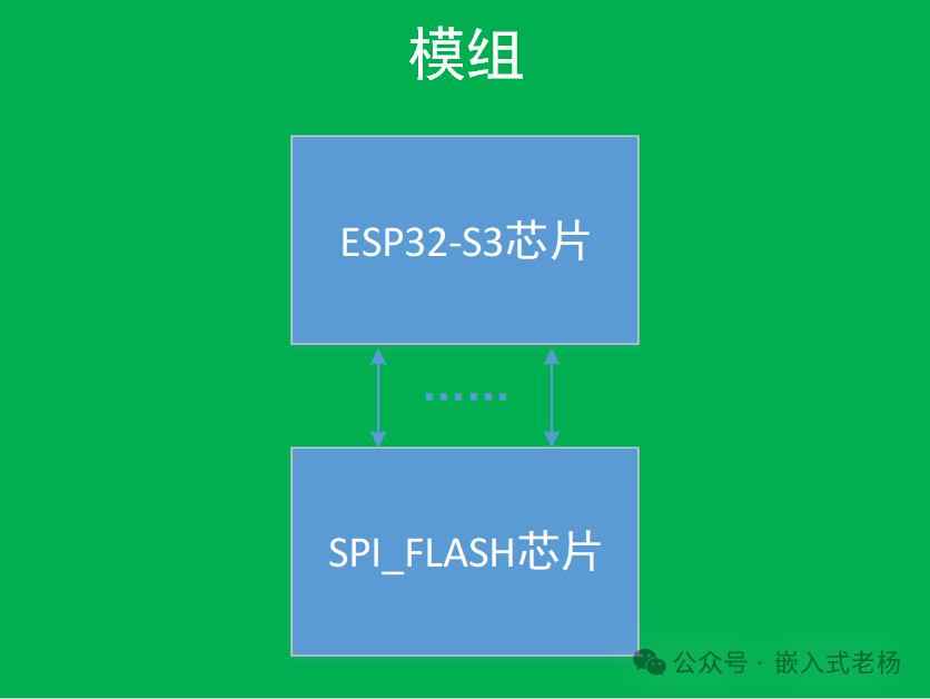
SPI Flash is an external independent chip, which needs to be connected to the ESP32-S3 via PCB. The ESP32-S3 chip itself does not integrate Flash, so all programs and data are stored in the external SPI Flash. Some modules (such as<span><span>ESP32-S3-WROOM-1</span></span>) integrate Flash with the SoC on the same PCB, but essentially remain external components.
3. Communication Protocols and Modes
·Basic SPI Mode: Uses 4 lines (CLK, CS, MOSI, MISO), supports standard SPI protocol;
·QSPI Mode: Transmits address and data simultaneously through 4 lines, increasing bandwidth by 4 times, requires Flash chip support (e.g.,<span><span>qio</span></span> or<span><span>qout</span></span> modes);
·OPI Mode (Octal SPI): 8 lines for parallel transmission, suitable for high-performance requirements, but requires specific Flash models.
4. ESP32-S3 is compatible with mainstream manufacturers’ SPI Flash, the following are typical models:
1. Winbond
• W25Q64JV: 8MB, supports QSPI, voltage 3.3V, package SOIC-8;
• W25Q128JV: 16MB, maximum clock frequency 133MHz, suitable for large capacity storage needs.
2.GigaDevice
• GD25Q32C: 4MB, low power design (<1mW), supports XIP (execute in place);
• GD25Q128C: 16MB, operating voltage 1.7V~3.6V, compatible with wide voltage systems.
3. Micron
• MT25QL128: 16MB, uses Octal SPI interface, suitable for high-speed data throughput scenarios.
02
—
How to Set Up the Partition Table
The partition table is a binary data structure stored at a fixed location in Flash (default 0x8000), recording the starting address, size, type, subtype, and other information of each partition. When the ESP32-S3 starts, the Bootloader first reads the partition table and then loads the corresponding partition program (e.g., app partition) or accesses data (e.g., NVS partition) based on the information in the table.
|
Partition Name |
Who is responsible for initialization |
Typical Trigger Code/Location |
Remarks |
|
nvs |
nvs_flash_init() |
User Code`app_main() |
Must be called manually |
|
phy_init |
Wi-Fi/BT protocol stack internally |
esp_wifi_init() or esp_bt_controller_init() |
Protocol stack automatically reads calibration data |
|
factory |
ROM bootloader + CMake link |
Power onROM directly mapped to address 0x10000 |
Application layer initialization not required |
|
vfs(FAT) |
esp_vfs_fat_spiflash_mount()` or esp_vfs_fat_register() |
User Code |
Example:fatfs_spiflash/main.c |
|
storage (SPIFFS) |
esp_spiffs_mount()` or esp_vfs_spiffs_register()` |
User Code |
Example:spiffsgen/main.c |
Specific process (taking the ESP-IDF framework as an example).
1.Format of the Partition Table
# Name, Type, SubType, Starting Offset, Size, Flags (optional)nvs, data, nvs, , 0x40000, # 4MB NVS partition (stores configuration)phy_init, data, phy, , 0x1000, # RF calibration data partitionfactory, app, factory, , 0x100000, # 1MB factory app partition (default program)ota_0, app, ota_0, , 0x100000, # 1MB OTA partition 0ota_1, app, ota_1, , 0x100000, # 1MB OTA partition 1vfs, data, fat, , 0x200000, # 2MB file system partitionType (Type): app (application) or data (data);
SubType (SubType): under app type there are factory (default program), ota_0~ota_15 (OTA partitions); under data type there are nvs, phy (RF data), fat (file system), etc.;
Offset: can be omitted (automatically allocated in order), but must ensure no overlap;
Size: supports KB (e.g., 64KB), MB (e.g., 2MB) or hexadecimal (e.g., 0x10000).
2. Manually Creating a Partition Table
Creation steps:
1)Create a partition table file: Create a new partitions.csv in the project root directory and fill in the partition information according to the above format.
2)Specify the partition table path:
-
In the project’s CMakeLists.txt, add:
set(PARTITION_TABLE_CSV partitions.csv) # Pointing to the custom partition table file-
Or set through the ESP-IDF configuration tool (menuconfig):
3)Enter Partition Table → Partition Table (Custom partition table CSV) → Input the custom CSV file path (e.g., partitions.csv).
3. VSCode ESP-IDF Project Automatically Creates Partition Table
In most cases, the partition table automatically created by VSCode ESP-IDF is used. The VSCode ESP-IDF project will use the default partition table (default_partitions.csv) provided by the framework, suitable for most basic scenarios (including factory app, nvs, phy_init, and other necessary partitions).
If using the default partition table: no additional operations are required, just compile (Build) and flash (Flash) normally, and VSCode will automatically handle the generation and flashing of the partition table.
4. Scenarios Requiring Modification of the Partition Table
1)Need to support OTA upgrades
The default partition table does not include OTA partitions. If wireless upgrade functionality is required, at least two OTA partitions (e.g., ota_0 and ota_1) must be added, for example:
csvota_0, app, ota_0, , 1M,ota_1, app, ota_1, , 1M,2)The default partition size is insufficient
If the NVS partition (default 5KB) cannot store device configurations (e.g., multiple WiFi passwords, sensor calibration data), its capacity needs to be increased (e.g., 0x40000, which is 256KB);
If using the FAT file system to store a large number of logs or files, it is necessary to add or expand the fat type partition (e.g., 2M).
3)Custom data partition requirements
When specific data (e.g., firmware backup, encryption keys) needs to be stored independently, a custom data partition can be added, for example:
csvfirmware_backup, data, 0x80, , 512KB, # Subtype 0x80 is custom4)Flash capacity exceeds the default partition table support range
The default partition table is suitable for Flash of 4MB or less. If using 8MB/16MB Flash and needing to fully utilize the space, the partition sizes need to be re-planned (e.g., expand the app partition to 4MB).
5)Multiple application switching
When multiple independent applications (e.g., main program + debugging program) need to run on the device, an independent app partition must be allocated for each application.
03
—
Initialization/Mounting of Each Partition
1. nvs
Whenever you intend to use NVS (non-volatile storage) to save/read key-value data, you must call nvs_flash_init() during the initialization phase. Without it, any nvs_open, nvs_set_*, nvs_get_* will directly return ESP_ERR_NVS_NOT_INITIALIZED.
esp_err_t ret = nvs_flash_init();if (ret == ESP_ERR_NVS_NO_FREE_PAGES || ret == ESP_ERR_NVS_NEW_VERSION_FOUND) { ESP_ERROR_CHECK(nvs_flash_erase()); ESP_ERROR_CHECK(nvs_flash_init());}2. phy_init (Wi-Fi/BT protocol stack internally, developers only need to start the protocol stack)
/* Wi-Fi example: the protocol stack will automatically read calibration data at 0xF000 */esp_netif_init();esp_event_loop_create_default();esp_netif_create_default_wifi_sta();wifi_init_config_t cfg = WIFI_INIT_CONFIG_DEFAULT();ESP_ERROR_CHECK(esp_wifi_init(&cfg)); // Internally loads phy_init3. factory (ROM bootloader runs directly, no code required at the application layer)
4. vfs (FAT) — Mount the 10 MB partition starting at 0x200000 as /vfs
#include "esp_vfs_fat.h"#include "wear_levelling.h"
#define FAT_PARTITION_LABEL    "vfs"wl_handle_t wl_handle;
void mount_fat(void){    esp_vfs_fat_mount_config_t mount_config = {        .max_files              = 8,        .format_if_mount_failed = true,        .allocation_unit_size   = 512    };    ESP_ERROR_CHECK(esp_vfs_fat_spiflash_mount_rw_wl(    "/vfs", FAT_PARTITION_LABEL, &mount_config, &wl_handle));}
5. storage (SPIFFS) — Mount the 4 MB partition starting at 0xC00000 as /spiffs
#include "esp_spiffs.h"
#define SPIFFS_PARTITION_LABEL "storage"
void mount_spiffs(void){    esp_vfs_spiffs_conf_t conf = {        .base_path        = "/spiffs",        .partition_label  = SPIFFS_PARTITION_LABEL,        .max_files        = 5,        .format_if_mount_failed = true    };    ESP_ERROR_CHECK(esp_vfs_spiffs_register(&conf));}
6. app_main() Template
void app_main(void){    /* 1. NVS initialization */    esp_err_t ret = nvs_flash_init();    if (ret == ESP_ERR_NVS_NO_FREE_PAGES ||        ret == ESP_ERR_NVS_NEW_VERSION_FOUND) {        ESP_ERROR_CHECK(nvs_flash_erase());        ESP_ERROR_CHECK(nvs_flash_init());    }
    /* 2. Wi-Fi/BT → Automatically use phy_init partition */    esp_netif_init();    esp_event_loop_create_default();    esp_netif_create_default_wifi_sta();    wifi_init_config_t wifi_cfg = WIFI_INIT_CONFIG_DEFAULT();    ESP_ERROR_CHECK(esp_wifi_init(&wifi_cfg));
    /* 3. Mount FAT file system */    mount_fat();
    /* 4. Mount SPIFFS file system */    mount_spiffs();
    /* 5. Main loop or other business logic */    for (;;) {        vTaskDelay(pdMS_TO_TICKS(1000));    }}