
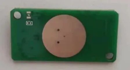
SY-RD3216LJ4 is an ultra-low power 5.8G radar sensor launched by Deep Cloud IoT, with an extreme power consumption of about 40uA. The module size is 32mm*16mm, and this module is paired with a miniaturized planar antenna, ensuring sensor performance while significantly reducing the overall size. This sensor can be used in various scenarios for detecting human presence or moving target sensing, including smart homes, smart doorbells, smart locks, etc., and is particularly suitable for low-power battery-operated scenarios such as night lights, solar street lights, and wireless cameras. The physical image of the module is as follows:

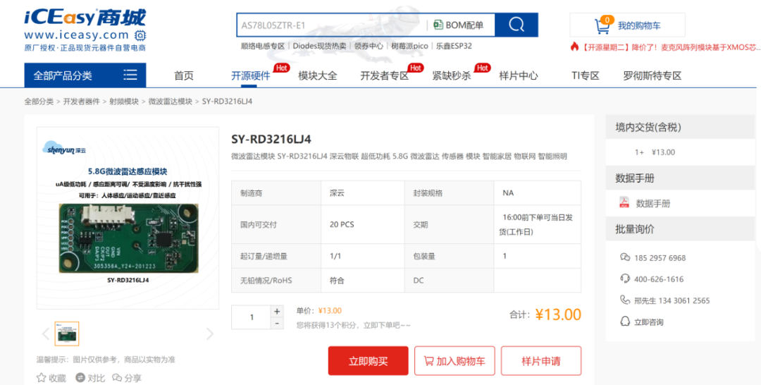
Sample application link:
https://www.iceasy.com/8572/1017703941.shtml
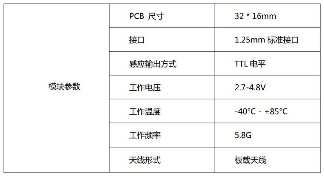
Basic parameters of the module:
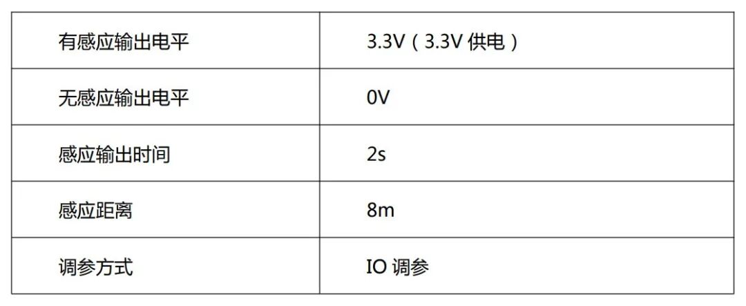
Factory default parameters:
Pin definitions:
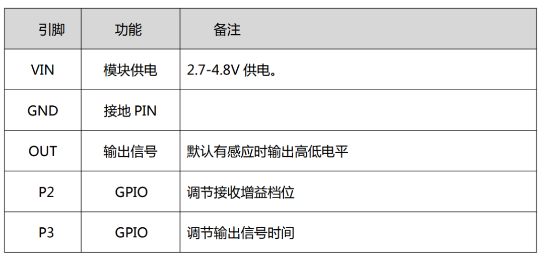
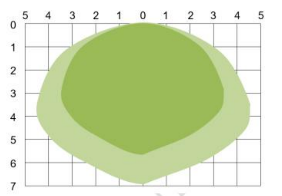
When communicating with the MCU, simply connect the VIN and GND pins, and connect the MCU’s IO port to the module’s OUT. The OUT pin outputs TTL level, outputting low level when there is no sensing and high level when there is sensing. Detection range: The sensitivity of the radar sensor can be configured by adjusting the resistor, with a forward limit sensing distance of 10 meters. The actual sensing distance can be adjusted as needed. The following is a schematic diagram of the radar detection range in typical scenarios. If the sensitivity is set higher, the detection range will also increase accordingly. The dark area in the diagram represents the high sensitivity area, which can be fully detected, while the light area represents the low sensitivity detection area, where objects can be basically detected.
All the above data is provided by the official documentation, and there is not much. The module’s minimum power consumption can reach 40 microamps, making it suitable for battery power. The sample I applied for should be the factory default, and the sensing output time, sensing sensitivity (the higher the sensitivity, the wider the measured range), and light-sensitive detection (the radar sensing will only start when the ambient light is below the set illuminance; if the light is too bright, the module will not start the sensing function) can all be customized. I should also be able to modify it, but it requires soldering the corresponding resistors and light-sensitive diodes (but I can’t do that).Microwave Radar Module mainly senses moving objects near the module, using the ESP32 ULP ADC to collect the output of the microwave radar module and set it to turn on the LED on the ESP for 0.5 seconds when there is sensing. The official documentation states that the output level is 0 when there is no sensing.
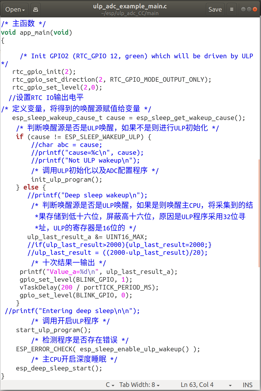
The C program is shown in the following figure:
First, define the LED pin; the LED on the ESP32 is connected to pin 2.

The main function is shown in the following figure. If the main CPU is awakened, the LED will turn on for 0.5 seconds and then turn off.
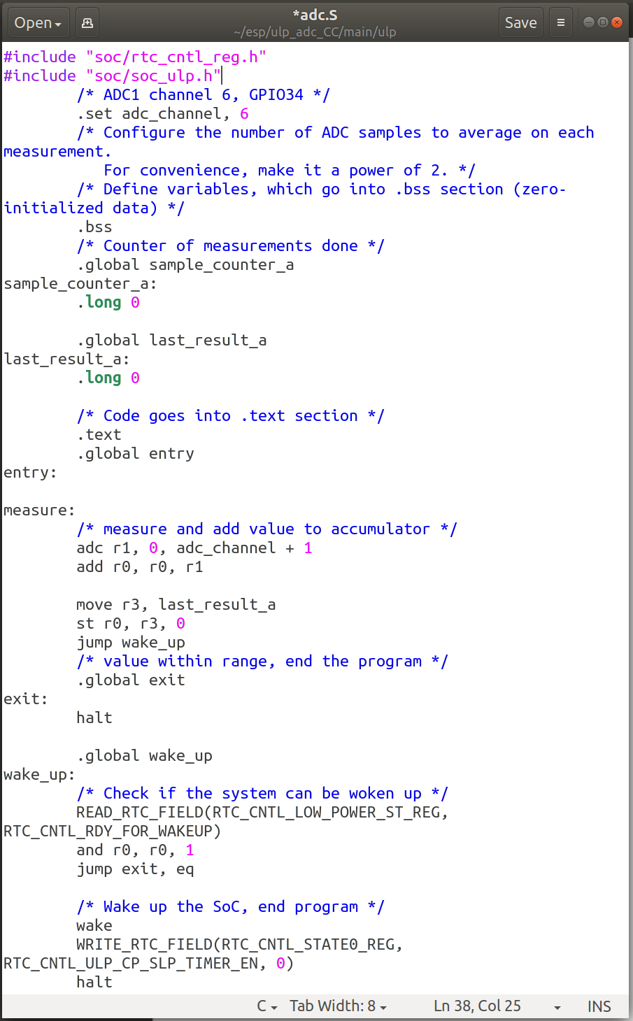
The assembly program is shown in the following figure:
I removed the original loop counting average part and directly collected the result once to determine whether to wake up the main CPU. If there is no sensing, the radar module outputs 0, and the main CPU will not be awakened. When there is sensing, the radar module outputs high level, waking up the main CPU and lighting the LED.
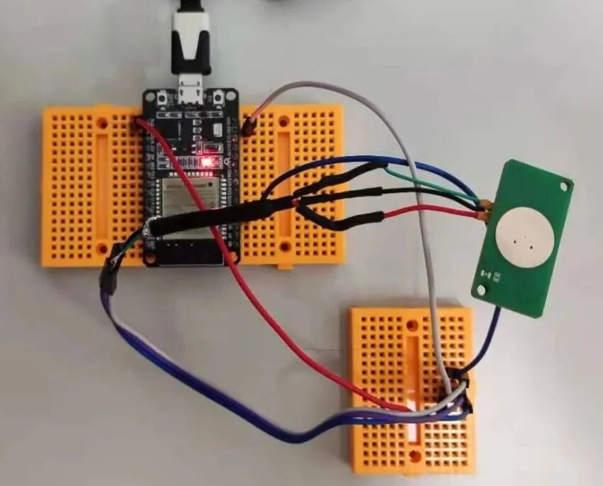
The hardware connection diagram is as follows:
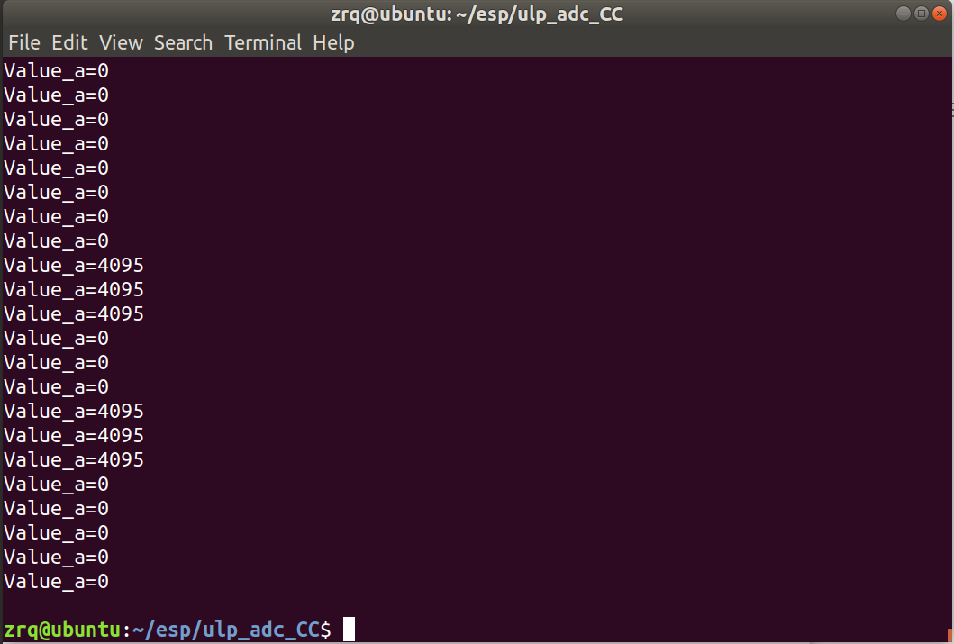
The program running result is shown in the following figure:
The video of data changes after sensing moving objects is as follows:
The video of LED changes after sensing moving objects is as follows:
It is possible that there are too many interfering objects near the module, and the sensing distance is not very far; it may also be a factory setting issue.
Another method, without using the ULP ADC function, directly uses the ESP32 to read the pin level.
The program is shown in the following figure:
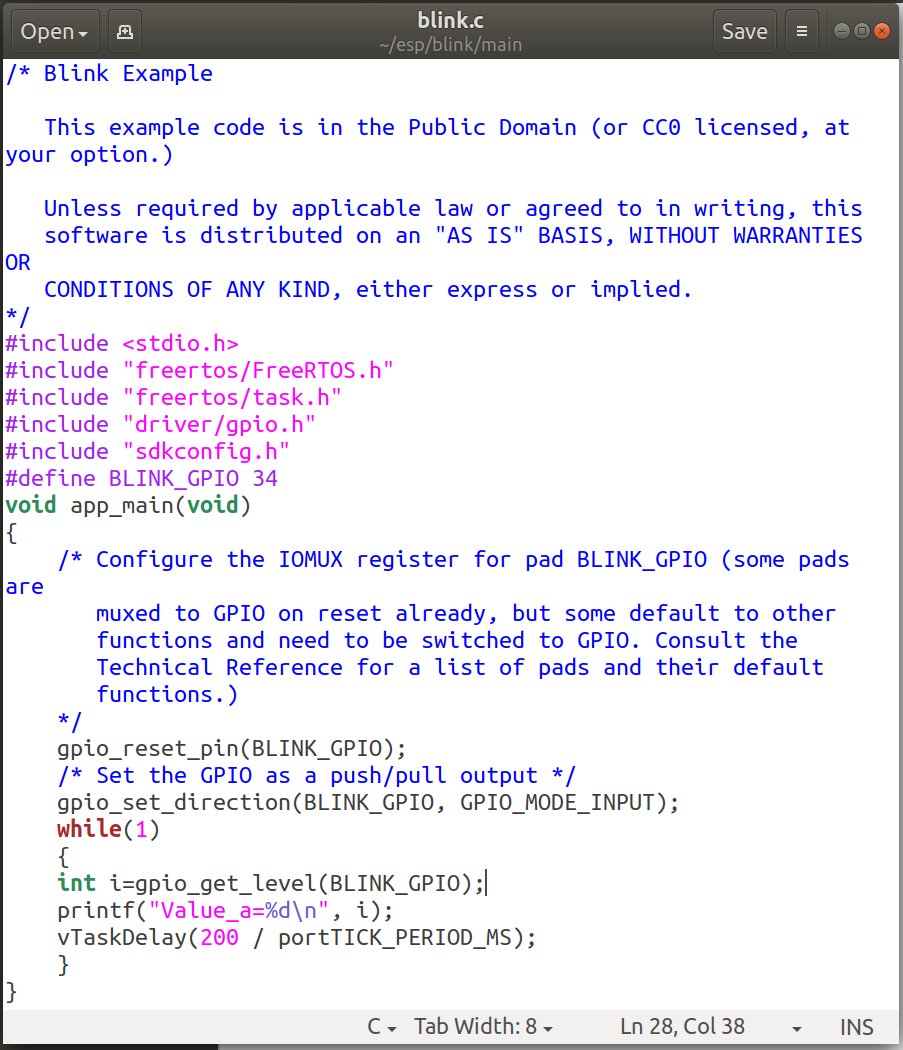
First, define the pin; in the main program, initialize the pin first, set the pin mode to input mode, and then loop to output and read the pin value, with a delay of 0.2 seconds.
The running result is shown in the following figure:
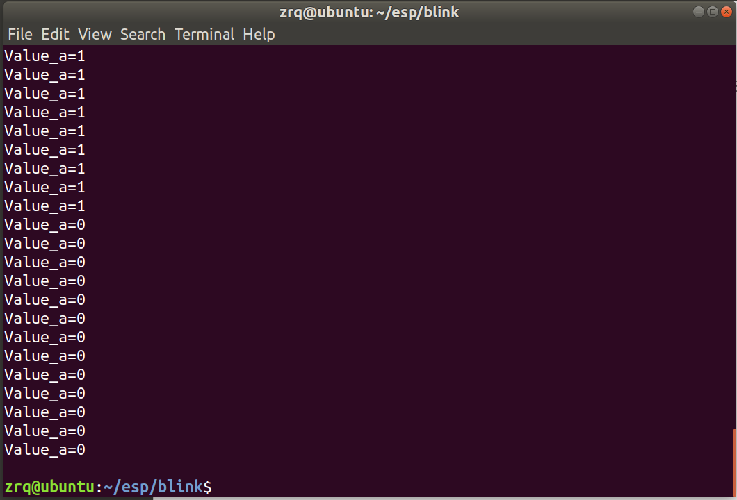
It can be found that the radar module outputs high and low levels of 1 and 0, respectively, meaning sensing is 1 and no sensing is 0.