In scenarios such as industrial automation, building control, and energy monitoring, RS-485 serial communication is widely used for data transmission between devices due to itslong-distance transmission capability, strong anti-interference ability, and support for multi-node communication. Especially in a master-slave structure, RS-485 is an ideal choice for achieving centralized control and distributed sensing.
However, during actual deployment, many engineers often encountercommunication interference between slave devices, bus confusion, and data loss, which severely affects communication quality and system stability. So, in the RS-485 master-slave communication structure, how can we effectively avoid interference between devices? This article will explain the principles and practical strategies to help you build a more stable and reliable RS-485 communication system.
1. Basic Principles and Structural Characteristics of RS-485 Communication
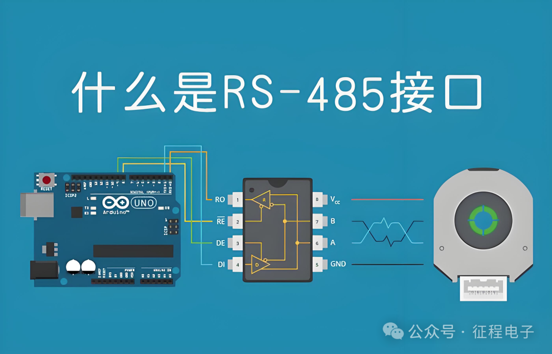
RS-485 is a differential signal communication standard that uses a pair of twisted pairs for data transmission, determining the logical state of data by comparing the voltage level differences between the “+” (A) and “-” (B) signals. This differential method gives RS-485 strong anti-interference capabilities, allowing for stable communication even in industrial wiring environments spanning hundreds of meters.
In a typical master-slave structure, the master device is responsible for polling multiple slave devices, while the slave devices respond passively based on the master device’s requests. This method requires thatonly one device is allowed to send data on the bus at any given time, otherwise, signal conflicts and data confusion will occur.
RS-485 supports a bus topology, allowing for a maximum of 32 standard devices to be connected (with expansion chips, this can be increased to 128 or even 256), but onlyone device can drive the signal line at a time, so coordinating communication timing and bus driving status is key to avoiding interference.
2. Common Interference Issues and Cause Analysis
In RS-485 master-slave communication, common interference issues between slave devices include:
1.Multiple slave devices responding simultaneously, causing bus conflicts.
This issue often arises in scenarios where the protocol is not standardized, addresses are set to be duplicate, or there are logical errors in the program.
2.Slave devices not releasing the bus in a timely manner, preventing the next device from communicating.
If a device remains in the “sending state” for an extended period, it will hinder the normal response of other nodes.
3.Bus reflections or echo signal interference affecting data discrimination.
Improper wiring or incorrect termination matching can cause signals to reflect back on the bus, affecting communication quality.
4.Electromagnetic interference causing bit errors.
Although RS-485 has anti-interference capabilities, it can still be affected in complex environments with strong electrical interference, such as those involving frequency converters.
3. Key Measures to Effectively Avoid Interference
To ensure the stable operation of the RS-485 master-slave communication system, the following design and deployment aspects are particularly critical:
1. Clearly Define Communication Protocols and Slave Address Allocation
All slave devices must haveunique address identifiers, and the master device should strictly send commands in a polling manner, with slave devices only responding when their addresses match, remaining in listening mode at all other times,eliminating “unauthorized” responses.
It is recommended to use standard communication protocols, such asModbus RTU, which inherently possesses the ability to avoid conflicts: slave devices have no active speaking rights and only respond to their own commands.
2. Control the Timing and Duration of Slave Device Transmission
After a slave device responds with data, it mustimmediately release the bus drive, setting the transmit pin (such as TX) to a high-impedance state to avoid “occupying” the bus. Using RS-485 chips with “automatic send control” (such as SP485, MAX485) can effectively manage the sending state.
In the program, it is essential to accurately control the serial port to disable the drive enable after sending is complete and set a reasonable response time interval to prevent multiple slave devices from “responding at once”.
3. Reasonable Terminal Matching and Bias Resistor Design
To avoid signal reflections, 120Ω termination resistors must be installed at both ends of the RS-485 bus, ensuring impedance matching. For long-distance wiring, bias resistors (such as 680Ω pulled up to +5V and pulled down to GND) can be added at the master device end or the middle of the bus to ensure that the bus level remains stable at a logical high during idle states.
If bias resistors are not set, the voltage on the signal line during idle states becomes uncertain, easily causing misjudgment at the receiving end.
4. Optimize Wiring Structure and Shielding Measures
Using twisted shielded pairs, and keeping the A and B lines symmetrically twisted, can effectively reduce common-mode interference. Communication lines should be kept away from high-voltage cables and strong interference sources, and wiring should avoid loops and star topologies, instead adopting a bus structure (i.e., “trunk line + short branches” mode), with a total bus length generally not exceeding 1200 meters.
Additionally, all devices’ grounding terminals should be well connected, and projects with conditions can use isolated RS-485 conversion modules to enhance the system’s anti-interference capability and electrical safety.
5. Application Example: Centralized Meter Reading for Smart Meters System
In a certain smart building project, dozens of electric meters are connected to a central controller via the RS-485 bus, using the Modbus RTU protocol for meter management. Initially, the system was unstable, and after investigation, it was found that multiple slave addresses were duplicated, termination resistors were not added, and the wiring had a star structure.
After standardizing numbering, adding termination resistors, and re-specifying wiring, the system stabilized. The controller polls one meter per second and sets a 200ms response window, effectively avoiding bus conflicts and data loss.
Conclusion
As a classic and stable communication method, RS-485 has been widely used in various industrial control scenarios. Although the master-slave network architecture is simple and efficient, it also imposes higher requirements on system design, protocol management, and electrical layout. By implementing reasonable address management, transmission control, termination matching, and wiring optimization measures, it is entirely possible to construct a stable and reliable RS-485 communication system that does not interfere with each other.
In the context of the continuous evolution of the Internet of Things and industrial digitization, RS-485 will continue to play an important role in numerous edge devices. Understanding and mastering its communication details is a necessary course for every engineer to achieve high-quality project implementation.