The FPM383C is a high-performance fingerprint recognition module characterized by fast recognition and high precision. Among many fingerprint sensors, the FPM383C is favored, especially by students working on graduation projects or course designs. Today, I will guide you through the fingerprint module (FPM383C) sensor.
1. Searching and Purchasing the Sensor
There are many websites to purchase sensors now, but for most university students or DIY enthusiasts, they often go to Taobao for selection and purchase. We can search for Taobao through Baidu and enter FPM383C in the search bar on the Taobao homepage, as shown below:

We find that it automatically pops up many suggestions, and we can directly click search without clicking on the recommendations. The following interface will appear, and there are quite a few stores to choose from. You can select any store since this sensor is already quite mature. Additionally, I suggest that you may need to purchase other sensors, so you can choose a store that sells a variety of sensors you might use.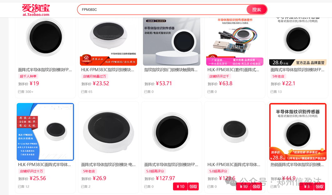
After selecting a store and entering, you will find the following parameter information:

Check whether the sensor parameters meet your project requirements. If they do, you can place an order and request some related materials from Taobao, which generally include basic code and documentation.

Upon opening the document, we can see relevant information, product overview, and application scope, which you can refer to for parameters and introductions in your thesis. I will not elaborate further here.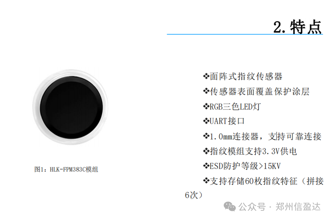
 As a developer or DIY enthusiast, we need to pay more attention to the relevant parameters of the sensor. We can see through the manual:
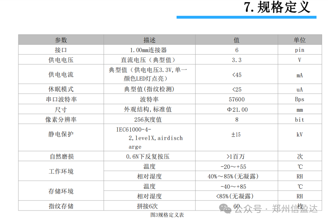
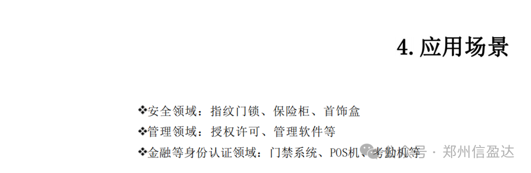
Suitable for fingerprint door locks, safes, jewelry boxes, authorization, management software, access control systems, POS machines, attendance machines, etc.
2. Fingerprint Sensor Communication Interface
After understanding the relevant parameters of the FPM383C sensor and selecting it, we need to know how to connect it to the microcontroller hardware, the communication protocol, and data parsing.
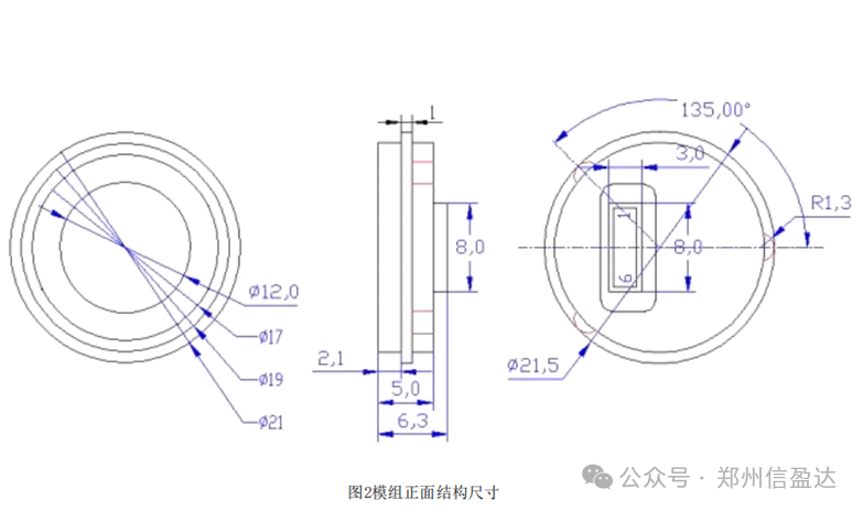
First, let’s look at how the FPM383C connects to the microcontroller:
Question 1: What are the pins of the FPM383C sensor, and what do they represent?
According to the data sheet, we find that the FPM383C sensor has 6 pins:
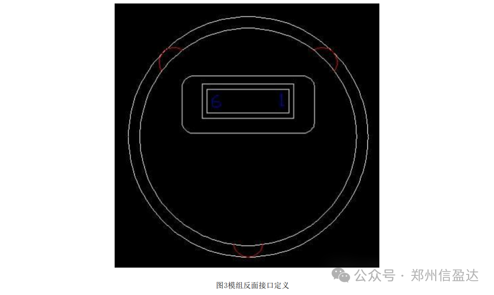
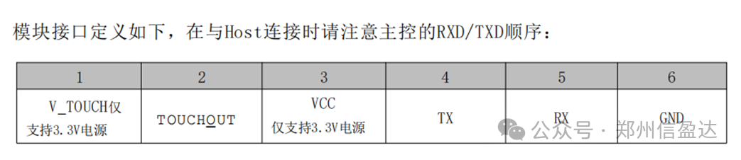
The pin descriptions are as follows:
1. V_TOUCH – Supports only 3.3V power supply
2. TOUCHOUT
3. VDD – Power supply 3.3V
4. TX – Transmit data
5. RX – Receive data
6. GND – Ground, negative power supply
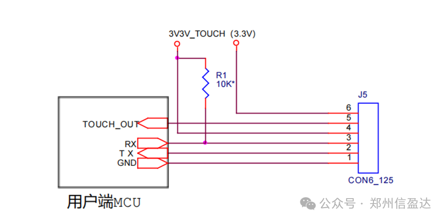
Question 2: How to connect the FPM383C pins to the microcontroller?
The fingerprint module has pins V_TOUCH, TOUCHOUT, VDD, TX, RX, GND. The V_TOUCH pin of the fingerprint module connects to PC1 of the STM32F407, which is used to control the power supply for the fingerprint module’s touch detection part. This pin can be controlled by the microcontroller to turn the touch detection function on or off. The TOUCHOUT pin connects to PC0 of the STM32F407 development board, used to output the touch detection status signal of the fingerprint module. VDD connects to 3.3V for power supply, the TX pin of the fingerprint module connects to the RX pin (PC7) of USART6 of the STM32F407, and the RX pin of the fingerprint module connects to the TX pin (PC6) of USART6 of the STM32F407. GND is connected to ground.
Through the above circuit connection, we find that the communication interface between the microcontroller and the FPM383C is serial. How do they communicate?
Serial communication uses standard serial communication protocols, ensuring data transmission accuracy by setting baud rate, data bits, stop bits, and parity bits.
3. Steps to Drive the FPM383C with STM32F407
Once we know how to drive the FPM383C, we can start practicing. Many people now use STM32 as the processing chip, so we will take STM32 driving as an example. The steps are as follows:
Step 1: Check the schematic to determine which pins of the FPM383C sensor correspond to the RX pin, TX pin, V_TOUCH pin, and TOUCHOUT pin of the microcontroller;
Step 2: Initialize and configure the GPIO pins;
Step 3: Drive the FPM383C according to the official data sheet to obtain sensor data;
Step 4: Save to the corresponding variable.
The specific implementation is as follows:
Step 1: Check the schematic to determine which pins of the FPM383C sensor correspond to the RX pin, TX pin, V_TOUCH pin, and TOUCHOUT pin of the microcontroller
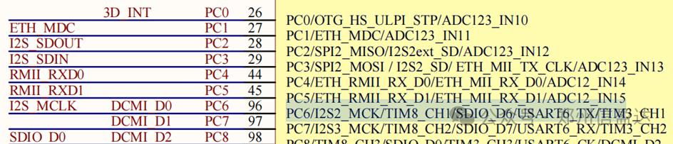
The RX pin of the FPM383C sensor connects to the TX pin (PC6) of the STM32 microcontroller, and the TX pin connects to the RX pin (PC7) of the STM32 microcontroller. When we need to drive the FPM383C, we configure the TX pin (PC6) of the STM32 microcontroller to multiplex push-pull output mode. When we need to read data from the FPM383C sensor, we configure the RX pin (PC7) of the STM32 microcontroller to floating input mode. The TOUCHOUT pin of the FPM383C sensor connects to the PC0 pin of the STM32 microcontroller, which is configured as input mode. The V_TOUCH pin of the FPM383C sensor connects to the PC1 pin of the STM32 microcontroller, which is configured as push-pull output mode.
Step 2: Initialize and configure the GPIO pins
void FingerPrintUsartInit(u32 bound){
	float USARTDIV;
	uint16_t DIV_Man;
	uint16_t DIV_Fra;
	//GPIO initialization:
	//PC6---Multiplexed to USART6_TX mode
	//PC7--Multiplexed to USART6_RX mode
	RCC->AHB1ENR |=0x01<<2;//Enable clock for port C
	FingerPrint_USART_PORT->MODER &=~(0x03<<(FingerPrint_USART_TXD_PIN*2) | 0x03<<(FingerPrint_USART_RXD_PIN*2));//Clear
	FingerPrint_USART_PORT->MODER |=(0x02<<(FingerPrint_USART_TXD_PIN*2) | 0x02<<(FingerPrint_USART_RXD_PIN*2));//PC6 and PC7 multiplexed function
	FingerPrint_USART_PORT->OTYPER &=~(0x01<<fingerprint_usart_txd_pin); fingerprint_usart_port-="" function="" multiplexed="" output="" pc6="" push-pull="">OSPEEDR &=~(0x03<<(FingerPrint_USART_TXD_PIN*2));//PC6 low speed 2Mhz
	FingerPrint_USART_PORT->PUPDR &=~(0x03<<(FingerPrint_USART_TXD_PIN*2) | 0x03<<(FingerPrint_USART_RXD_PIN*2));//PC6 and PC7 floating
	if(FingerPrint_USART_TXD_PIN<8)
	{
		FingerPrint_USART_PORT->AFR[0] &=~(0xF<<(FingerPrint_USART_TXD_AFIO_PIN*4));
		FingerPrint_USART_PORT->AFR[0] |=(FingerPrint_USART_TXD_AFIO<<(FingerPrint_USART_TXD_AFIO_PIN*4));
	}
	else
	{
		FingerPrint_USART_PORT->AFR[1] &=~(0xF<<(FingerPrint_USART_TXD_AFIO_PIN*4));
		FingerPrint_USART_PORT->AFR[1] |=(FingerPrint_USART_TXD_AFIO<<(FingerPrint_USART_TXD_AFIO_PIN*4));
	}
	if(FingerPrint_USART_RXD_PIN<8)
	{
		FingerPrint_USART_PORT->AFR[0] &=~(0xF<<(FingerPrint_USART_RXD_AFIO_PIN*4));
		FingerPrint_USART_PORT->AFR[0] |=(FingerPrint_USART_RXD_AFIO<<(FingerPrint_USART_RXD_AFIO_PIN*4));
	}
	else
	{
		FingerPrint_USART_PORT->AFR[1] &=~(0xF<<(FingerPrint_USART_RXD_AFIO_PIN*4));
		FingerPrint_USART_PORT->AFR[1] |=(FingerPrint_USART_RXD_AFIO<<(FingerPrint_USART_RXD_AFIO_PIN*4));
	}
	//Configure USART6
	RCC->APB2ENR |=0x01<<5;//Enable module clock--84Mhz
	FingerPrint_USART->CR1=0;//Clear register
	FingerPrint_USART->CR2 &=~(0x03<<12);
	/*
	16 times oversampling
	1 start bit, 8 data bits, 1 stop bit
	Disable parity control
	*/
	//Baud rate setting
	USARTDIV=84000000.0/(16*bound);
	DIV_Man=USARTDIV;
	DIV_Fra=(USARTDIV-DIV_Man)*16+0.5;
	FingerPrint_USART->BRR=DIV_Man<<4  | DIV_Fra;
	//FingerPrint_USART->CR1 |=0X01<<4;  //Enable idle interrupt
	FingerPrint_USART->CR1 |=0X01<<5; //Enable receive buffer not empty interrupt
	//Set UART1 priority in NVIC and enable UART1 interrupt
	NVIC_SetPriority(USART6_IRQn,NVIC_EncodePriority(7-2,3,3));
	NVIC_EnableIRQ(USART6_IRQn);
	FingerPrint_USART->CR1 |=0x01<<3;//Enable transmitter
	FingerPrint_USART->CR1 |=0x01<<2;//Enable receiver
	FingerPrint_USART->CR1 |=0x01<<13;//Enable serial port
}
</fingerprint_usart_txd_pin);>
Step 3: Drive the FPM383C according to the official data sheet to obtain sensor data
//Receive data from the fingerprint module
uint8_t FingerPrintDataRev(uint8_t *pDatBuf,uint16_t DataLen,uint16_t TimeOutMs){
	uint16_t i;
	while(TimeOutMs--)
	{
		if (RevDtaNum-RevDtaOffset>=DataLen)
		{
			for (i=0;i<datalen;i++) !="0))" &crerr,="" &nbuflen,="" &ninbuflen,="" (crerr="" 0,="" <="" and="" automatically="" break;="" buf,="" buf[0]="1;" buf[128];="" cmd_err;="" cmd_ok;="" code="" continue;="" crerr;="" cret="CommSingleInstruction(MASK_INS," cret,="" cret;="" delayms(1);="" do{="" during="" else="" execution="" features="" fingerprint="" fptex_autovery(void){="" fptex_savechar(void){="" from="" function,="" get="" i;="" if((cret="" if(cret="CMD_TIMEOUT)" images="" memset(buf,="" n;="" nbuflen="1;" ninbuflen="1;" nouttimems="500;" nouttimems);="" novertime="500;" novertime);="" novertime,="" null,="" obtain="" pdatbuf[i]="UartRxBuff[RevDtaOffset+i];" ps_genchar,="" ps_getenrollimage,="" ps_getimage,="" ps_match,="" ps_upchar,="" return="" revdtaoffset+="DataLen;" rt_ok;="" rt_overtime;="" save="" sensor="" sizeof(buf));="" the="" uint16="" uint8="" verify="" while(1)="" will="" {="" ||="" }="" }while(1);=""></datalen;i++)>
The fingerprint data saved by the fingerprint module is stored in the FingerPrintDataRev function, which achieves data storage by passing the address of the variable.
Step 4: Save to the corresponding array
The collected fingerprint image data will be saved in the Buf array.
UINT8 Buf[128];
CommSingleInstruction(MASK_INS, PS_GetEnrollImage, Buf, &nBufLen, Buf, &cRerr, nOutTimeMS);
4. Printing Fingerprint Data via Serial Port
Through the above steps, we have been able to obtain the fingerprint collection status. Next, considering that everyone uses different screens, we will print the fingerprint collection status via Serial Port 1.
Step 1: Initialize Serial Port 1
Step 2: Write the fputc function
Step 3: Directly call the printf function to print
The specifics are as follows:
Step 1: Initialize Serial Port 1
/******************************************************************************************
Function: Usart1Init
Description: Serial Port 1 Initialization
Input: Baud rate
*****************************************************************************************/
void Usart1Init(uint32_t bond){
	float USARTDIV;
	uint16_t DIV_Man;
	uint16_t DIV_Fra;
	//GPIO initialization:
	//PA9---Multiplexed to USART1_TX mode
	//PA10--Multiplexed to USART1_RX mode
	RCC->AHB1ENR |=0x01<<0;//Enable clock for port A
	GPIOA->MODER &=~(0x0F<<18);//Clear
	GPIOA->MODER |=(0x0a<<18);//PA9 and PA10 multiplexed function
	GPIOA->OTYPER &=~(0x01<<9);//PA9 multiplexed function push-pull output
	GPIOA->OSPEEDR &=~(0x03<<18);//PA9 low speed 2Mhz
	GPIOA->PUPDR &=~(0x0F<<18);//PA9 and PA10 floating
	GPIOA->AFR[1] &=~(0xFF<<4);
	GPIOA->AFR[1] |=(0x77<<4);//PA9---Multiplexed to USART1_TX
								//PA10--Multiplexed to USART1_RX
	//Configure USART1
	RCC->APB2ENR |=0x01<<4;//Enable module clock--84Mhz
	USART1->CR1=0;//Clear register
	USART1->CR2 &=~(0x03<<12);
	/*
	16 times oversampling
	1 start bit, 8 data bits, 1 stop bit
	Disable parity control
	*/
	//Baud rate setting
	USARTDIV=84000000.0/(16*bond);
	DIV_Man=USARTDIV;
	DIV_Fra=(USARTDIV-DIV_Man)*16+0.5;
	USART1->BRR=DIV_Man<<4  | DIV_Fra;
	//USART1->CR1 |=0X01<<4;  //Enable idle interrupt
	USART1->CR1 |=0X01<<5; //Enable receive buffer not empty interrupt
	//Set UART1 priority in NVIC and enable UART1 interrupt
	NVIC_SetPriority(USART1_IRQn,NVIC_EncodePriority(7-2,3,3));
	NVIC_EnableIRQ(USART1_IRQn);
	USART1->CR1 |=0x01<<3;//Enable transmitter
	USART1->CR1 |=0x01<<2;//Enable receiver
	USART1->CR1 |=0x01<<13;//Enable Serial Port 1
}
Step 2: Write the fputc function
/****************************************************
Function Name: fputc
Parameter: ch represents the parameter to be obtained
*f represents the place where data is saved
Return Value: Returns the obtained parameter
Function Functionality: User call of printf function
****************************************************/
int fputc (int ch, FILE *f){
	while(USART_GetFlagStatus(USART1,USART_FLAG_TXE) == RESET);//Check if the serial port has finished sending data
	USART_SendData(USART1,ch);//Get data from the register
	return ch;
}
Step 3: Directly call the printf function to print
/*****************************************************************************************************
Subroutine : FunHandshakeModule
Function : Fingerprint registration routine
Input : UINT8 nTime -- Number of times to press the finger during registration
UINT16 wID -- Fingerprint ID number
Output : Success: CMD_OK Failure: CMD_ERR, Timeout: CMD_TIMEOUT
Description :
1. Master->Slave: Send image capture command to capture fingerprint
2. Slave->Master: Return the result of fingerprint capture.
3. If no fingerprint is captured, loop steps 1 and 2 until a fingerprint is captured or timeout
4. Extract features
5. Repeat steps 1 to 4, if registration requires 3 times, repeat step 5
6. Synthesize template
7. Save fingerprint
***************************************************************************************************/
UINT8 ExampleErollFp(UINT8 nTime){
UINT8 cRet, ERR, nErrTime, n;
UINT8 Buf[128];
UINT16 lenPkg;
UINT16 wID;
uint16_t IndexTable[256];//Due to code runtime errors, local variables occupy a large space, so only process 1 page index ID reading;
UINT16 i=0;
//0. First handshake to see if the module is working normally
cRet = FunHandshakeModule(1);
if (cRet != CMD_OK)
{
//Module is not normal, try again
cRet = FunHandshakeModule(1);
if (cRet != CMD_OK)
{
//Module is not normal
printf("Module is not normal");
return RT_OVERTIME;
}
}
//Get the registered ID index list to specify a blank ID for registration
cRet = FunReadIndexTableModule(1,IndexTable);//Only take 1 page ID, put it in the array
if(cRet == CMD_OK)
{
for(i=0;i<1024;i++)
{
if(i<indextable[i]) %d="" (1);="" (cret="CMD_OK&&ERR==0)" (err="0x15)" 0,="" 02h="" 05h="" 06h="" 1="" 1.="" 128);="" 29h="" <="" are="" break;="" buf,&err,1000);="" buf,&err,500);="" buf,&lenpkg,="" buf[0]="1;" buf[1]="(wID" buffer="" but="" capture="" captured="" captured,="" cmd_step_err;="" cmd_sum_err="" cmd_timeout;="" code="" continue;="" cret="%d," current="" default="" delayms(1000);="" do="" else="" err='%d\r\n",cRet,ERR);' error="" error\r\n");="" extract="" extraction="" failed="" feature="" features="" features:="" few="" finger\r\n",n);="" fingerprint="" generate="" if="" image="" images="" in="" indicates="" instruction="" is="" lenpkg="0;" merge="" messy="" n="0;" n++;="" nerrtime="0;" no="" normal,="" ntime)="" null,&lenpkg,="" original="" packet="" please="" points="" press="" previous="" printf("capture="" printf("collecting="" printf("extracting="" printf("fingerprint="" printf("merge="" printf("merging="" ps_genchar,="" ps_getenrollimage,="" ps_regmodel,="" related="" return="" store="" successful="" successful\r\n");="" sy_memset(buf,="" template="" template:="" that="" the="" there="" time,="" timeout\r\n");="" to="" too="" valid="" wait...\r\n");="" while(n="" wid="i;" your="" {="" }="" }while="">>8);
Buf[2]= (wID&0xff);
lenPkg=3;
cRet=CommSingleInstruction(MASK_INS,PS_StoreChar, Buf,&lenPkg, Buf,&ERR,500);
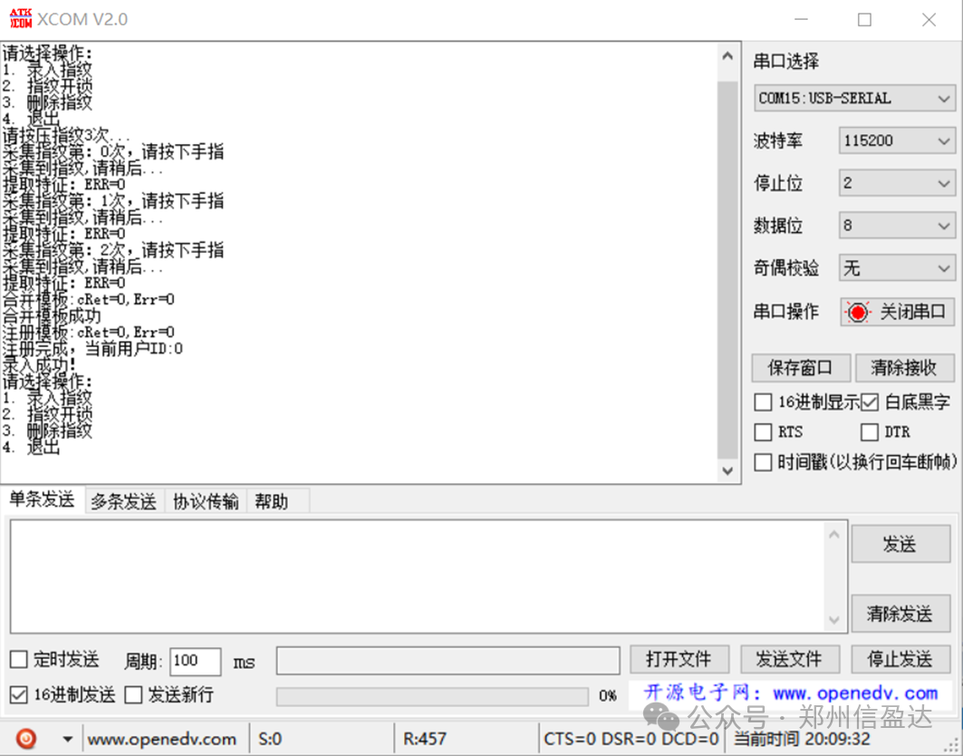
printf("Registering template: cRet=%d, Err=%d\r\n",cRet,ERR);
if (cRet==CMD_OK&&ERR==0) //Registration successful
{
printf("Registration completed, current user ID:%d\r\n",wID);
return CMD_OK;
}
else //Registration failed
{
return CMD_STEP_ERR;
}
}
</indextable[i])>5. Main Function Call
int main(void){
uint32_t MCU_ID[3]={0};
uint8_t data=0x11;
uint8_t ret;
uint16_t finger_id = 0; // Used to store fingerprint ID
uint8_t key_value; // Used to store the key value obtained from the capacitive keyboard
DelayInit();
Usart1Init(115200);
At24c02Init();
BS8116Init();
MFRC_Init();
st7789vm_init();
ZY002Port_Init();
VoiceInit();
RtcInit();
MotorInit();
W25Q64Init();
while(1)
{
printf("Please select an operation:\r\n1. Enroll fingerprint\r\n2. Fingerprint unlock\r\n3. Delete fingerprint\r\n4. Exit\r\n");
// Wait for capacitive keyboard to press a key
while (1) {
if (!BS8116_IRQ) {
key_value = BS8116ReadKey();
if (key_value && key_value != 0xFF) {
break;
}
}
}
// Convert key value to corresponding selection
uint8_t choice = key_value - '0';
switch (choice) {
case 1: // Enroll fingerprint
printf("Please press the fingerprint 3 times...\r\n");
ret = ExampleErollFp(3);
if (ret == CMD_OK) {
printf("Enrollment successful!\r\n");
FingerNum++; // Update fingerprint count
} else {
printf("Enrollment failed! Error code:%d\r\n", ret);
}
break;
case 2: // Fingerprint unlock
printf("Please press the fingerprint...\r\n");
ret = ExampleSeachFp(&finger_id);
if (ret == CMD_OK) {
printf("Unlock successful! User ID:%d\r\n", finger_id);
//Motor_Open(); // Execute unlock
} else {
printf("Unlock failed!\r\n");
}
break;
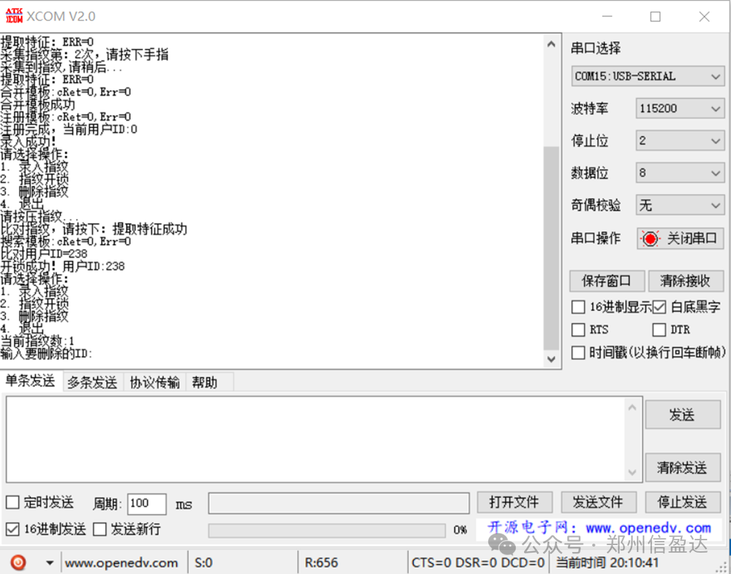
case 3: // Delete fingerprint
printf("Current fingerprint count:%d\r\nInput the ID to delete:", FingerNum);
// Wait for capacitive keyboard input for the ID to delete
while (1) {
if (!BS8116_IRQ) {
key_value = BS8116ReadKey();
if (key_value && key_value != 0xFF) {
finger_id = key_value - '0';
break;
}
}
}
ret = FunDeleteIDModule(finger_id, 1);
if (ret == CMD_OK) {
printf("Deletion successful!\r\n");
FingerNum--;
} else {
printf("Deletion failed!\r\n");
}
break;
case 4: // Exit
return 0;
break;
default:
printf("Invalid input!\r\n");
}
}
}
6. Running Effects
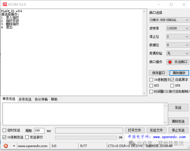
6.1. The menu options pop up on startup
(1) Please select an operation
① Enroll fingerprint
② Fingerprint unlock
③ Delete fingerprint
④ Exit
6.2. I choose ① Enroll fingerprint, a prompt box will pop up“Please press the fingerprint 3 times”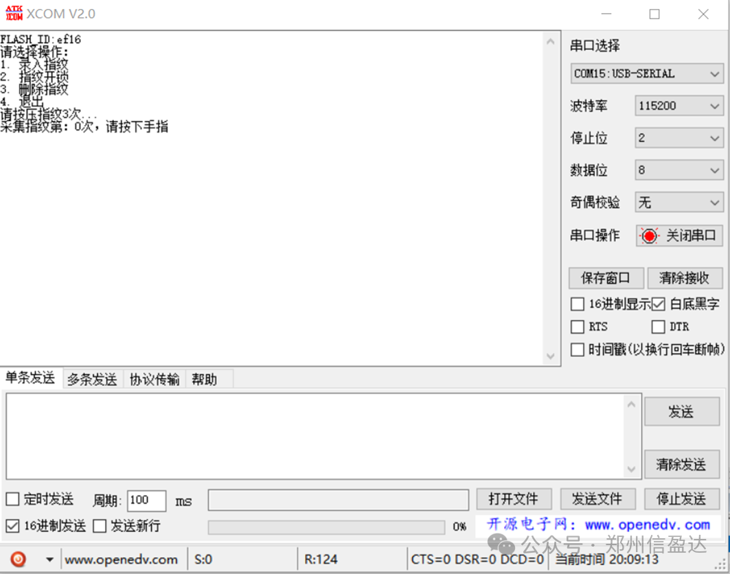
 6.3. After successfully enrolling the fingerprint, choose ② Fingerprint unlock
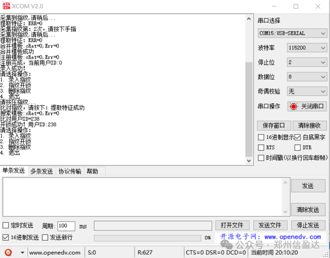
6.4. If the fingerprint is correct, it will prompt “Unlock successful!”, if the fingerprint is incorrect, it will prompt “Unlock failed”
6.5. You can choose ③ Delete fingerprint
The above is the entire process of collecting and processing fingerprints using the FPM383C under STM32 control. If you have any questions, you can scan the QR code below to interact in the live broadcast room.