1. Introduction to H-JTAG:
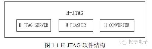
H-JTAG is a simple and easy-to-use debugging proxy software, similar in functionality to the popular MULTI-ICE. H-JTAG includes three software tools: H-JTAG SERVER, H-FLASHER, and H-CONVERTER. Among them, H-JTAG SERVER implements the debugging proxy function, H-FLASHER implements the FLASH programming function, and H-CONVERTER is a simple file format conversion tool that supports conversion of common file formats.
The basic structure of H-JTAG is shown in the figure below.
H-JTAG supports debugging for all CORTEX-M3, ARM7, ARM9, and XSCALE-based chips, and it is compatible with most mainstream ARM debugging software such as ADS, RVDS, IAR, and KEIL/MDK. With flexible interface configuration, H-JTAG can support WIGGLER, SDT-JTAG, various user-defined JTAG debugging boards, and H-JTAG USB high-speed emulator. Additionally, the accompanying H-FLASHER programming software supports programming for commonly used on-chip and off-chip FLASH. By using H-JTAG, users can easily establish a simple and user-friendly ARM debugging development platform. The functions and features of H-JTAG are summarized as follows:
(1) Supports RDI 1.5.0 and 1.5.1;
(2) Supports all CORTEX-M3, ARM7, ARM9, and XSCALE chips;
(3) Supports THUMB and ARM instructions;
(4) Supports LITTLE-ENDIAN and BIG-ENDIAN;
(5) Supports SEMIHOSTING;
(6) Supports WIGGLER, SDT-JTAG, custom JTAG debugging boards, and H-JTAG USB emulator;
(7) Supports WINDOWS 9.X/NT/2000/XP/VISTA;
(8) Supports programming for common on-chip FLASH, NOR FLASH, and NAND FLASH chips;
(9) Supports automatic downloading of on-chip FLASH for LPC1700/2000, AT91SAM, LUMINARY, and STM32F series;
2. H-JTAG Debugging/Programming Structure
H-JTAG supports ARM’s RDI interface. Through the RDI interface, H-JTAG can support most mainstream ARM debugging software.
The debugging structure is shown in Figure 1-2.
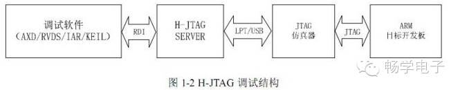
The debugging software (AXD/RVDS/IAR/KEIL) interacts with H-JTAG SERVER via the RDI interface. H-JTAG SERVER connects to the JTAG emulator through parallel/USB. H-JTAG provides flexible JTAG interface settings and supports both parallel and USB interface emulators. By configuring, H-JTAG can support different types of JTAG debugging boards, such as the popular WIGGLER, SDT-JTAG, and users can also use custom JTAG debugging boards as needed. Besides debugging, users can also use H-FLASHER to program and download programs and data to FLASH chips. Currently, H-FLASHER supports common on-chip and off-chip FLASH chips. With software updates and upgrades, the types of chips supported by H-FLASHER will continue to increase. During FLASH programming, the connection between H-FLASHER and H-JTAG SERVER is shown in the figure below:
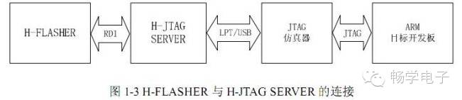
When programming FLASH, the interaction between H-FLASHER and H-JTAG is very similar to debugging. H-FLASHER interacts with H-JTAG SERVER via the RDI interface to access and control the target development board. Based on the configuration file provided by the user, H-FLASHER ultimately completes the FLASH programming task.
3. ARM Cores Supported by H-JTAG
H-JTAG supports debugging and programming for common ARM cores. Please refer to the list below:
CORTEX-M3, ARM7TDMI, ARM7TDMI-S, ARM720T, ARM740T, ARM9TDMI, ARM920T, ARM922T, ARM940T, ARM926EJ-S, ARM946E-S, ARM966E-S, ARM1136, ARM1176, PXA21X, PXA25X, PXA27X, PXA3XX, IXP4XX;
Note: The cable should not be too long, or the download speed will be slow and debugging will be unstable, leading to frequent errors!
Optional: If you do not have a parallel cable extension on hand, you can add a parallel cable (price: 10 yuan)
5. Download Debugging Software:
It is recommended to use H-JTAG V0.6.3 for debugging.
6. For detailed use of the emulator, please read the Chinese user manual carefully after installing the above software. The following are brief usage steps for reference:
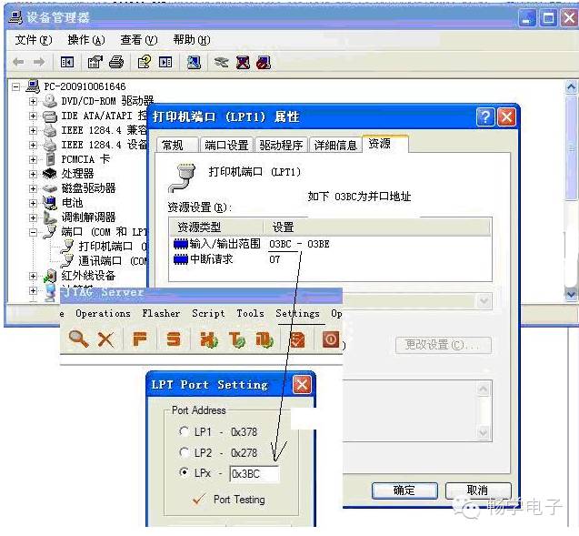
(1) LPT JTAG setup
(2) Set parallel port address
(3) Set debugging target
(4) Add chip ID
(Refer to: Configuration User Manual)
Using H-JTAG to debug LPC2138 involves the following steps:
Step 1: After starting H-JTAG, click the Detect target icon in the image below to find the chip:
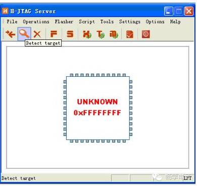
After successful detection, click the “F” button in the image above to see the following:
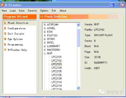
Select NXP LPC2103 in Flash Selection, then click Configuration as shown below:
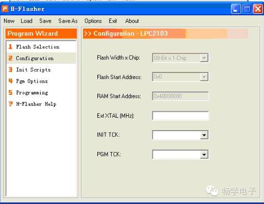
In the ExtXTAL(HMZ) field, fill in the crystal frequency, leave other fields empty.
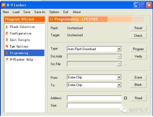
Click on the Programming item, as shown in the image: click the CHECK button to complete the FLASH check.
Common Issues:
Why can’t I program into FLASH with H-JTAG, or why does it run incorrectly after programming?
Solution:
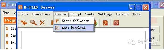
Please check the “Auto Download” option.
If the parallel port on your computer is not the system default, please configure it correctly, the method is as follows: