This article describes how to use PWM waveform output on a platform equipped with the RT-Thread operating system, including the application, configuration, and driver addition of PWM. A code example verified on the ZhiDian atom STM32L475 pandora development board is provided.
Introduction to Hardware Platform
<span>STM32L475 pandora</span> development board, providing specific application example codes for PWM. Due to the generality of the RT-Thread upper application API, these codes are not limited to specific hardware platforms, and users can easily port them to other platforms.<span>STM32L475 pandora</span> is a development board launched by ZhiDian atom based on the <span>ARM Cortex-M4</span> core, with a maximum frequency of 80MHz. This development board has rich onboard resources that can fully utilize the chip performance of STM32L475.
Using PWM
Open PWM Channel in menuconfig
<span>Hardware Driver Config ---> On-chip Peripheral Drivers ---> Enable pwm ---> Enable timer2 output pwm</span> as shown in the figure below: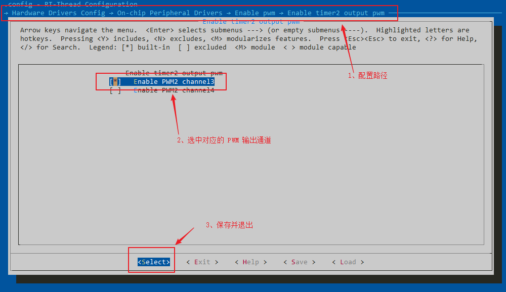
<span>scons --target=mdk5</span> to generate the mdk5 project, open the project to compile and download the program. Enter the command <span>list_device</span> in the terminal to see that the PWM2 device has been successfully added, as shown in the figure below:
Using PWM to Output Waveform

🔗Link:
https://www.rt-thread.org/document/site/programming-manual/device/pwm/pwm/
(Please copy the above link to an external browser to open)
Steps to Use PWM Device
-
Initialize the PWM device. ⚪ Use rt_device_find to find the specified PWM device. ⚪ Use rt_pwm_set to set the default PWM cycle and pulse width of the channel. ⚪ Use rt_pwm_enable to enable the PWM channel that needs to output the waveform. -
Use the PWM device to output the waveform. ⚪ Use rt_pwm_set to output a specific waveform. -
Close the PWM output channel. ⚪ When the PWM channel output waveform is no longer needed, rt_pwm_disable can be called to close the corresponding output channel.
 1#define PWM_DEV_NAME            "pwm2"  /* PWM device name */
 2#define PWM_DEV_CHANNEL         3       /* PWM channel */
 3#define THREAD_PRIORITY         25      /* Thread priority */
 4#define THREAD_STACK_SIZE       512     /* Thread stack size */
 5#define THREAD_TIMESLICE        5       /* Thread time slice size */
 6
 7static rt_thread_t tid1 = RT_NULL;      /* Thread handle */
 8struct rt_device_pwm *pwm_dev;          /* PWM device handle */
 9static rt_uint32_t period = 500000;     /* Period is 0.5ms, unit is nanoseconds ns */
10static rt_uint32_t pulse = 0;           /* PWM pulse width value increase and decrease direction */
11
12/* Entry function of thread pwm_entry */
13static void pwm_entry(void *parameter)
14{
15    rt_uint32_t count = 0;
16
17    while (count++ < 1000)
18    {
19        rt_thread_mdelay(50);
20        /* step 2, set PWM period and pulse width, output specific waveform */
21        rt_pwm_set(pwm_dev, PWM_DEV_CHANNEL, period, pulse++);
22    }
23    /* step 3, if the channel is no longer used, the PWM channel output can be turned off */
24    rt_pwm_disable(pwm_dev, PWM_DEV_CHANNEL);
25}
26
27static int pwm_test(int argc, char *argv[])
28{
29    /* step 1.1, find PWM device */
30    pwm_dev = (struct rt_device_pwm *)rt_device_find(PWM_DEV_NAME);
31    if (pwm_dev == RT_NULL)
32    {
33        rt_kprintf("pwm sample run failed! can't find %s device!\n", PWM_DEV_NAME);
34        return RT_ERROR;
35    }
36
37    /* step 1.2, set default values for PWM period and pulse width */
38    rt_pwm_set(pwm_dev, PWM_DEV_CHANNEL, period, pulse);
39    /* step 1.3, enable the output channel of the PWM device */
40    rt_pwm_enable(pwm_dev, PWM_DEV_CHANNEL);
41
42    /* Create thread, name it pwm_thread, entry is pwm_entry*/
43    tid1 = rt_thread_create("pwm_thread",
44                             pwm_entry,
45                             RT_NULL,
46                             THREAD_STACK_SIZE,
47                             THREAD_PRIORITY,
48                             THREAD_TIMESLICE);
49
50    /* If the thread control block is obtained, start this thread */
51    if (tid1 != RT_NULL)
52        rt_thread_startup(tid1);
53
54    return RT_EOK;
55}
56/* Export to msh command list */
57MSH_CMD_EXPORT(pwm_test, pwm sample);

Running the PWM Test Program
Adding PWM Driver
Check if the driver file supports PWM
<span>rt-thread\bsp\stm32\libraries\HAL_Drivers</span> directory to check whether the drv_pwm.c file supports the corresponding PWM peripheral output. Check whether the driver file supports the corresponding PWM peripherals (PWM1, 2, n)

Initialize PWM Channel Pins
<span>rt-thread\bsp\stm32l475-atk-pandora\board\CubeMX_Config</span> directory and double-click to open <span>STM32L475VE.ioc</span> file to initialize the pins corresponding to the PWM channel, taking PWM2 channel 3 as an example, as shown in the figure below:
<span>GENERATE CODE</span> button to generate the code. Although STM32CubeMX generates multiple files for initializing peripherals, RT-Thread only uses the STM32CubeMX generated <span>stm32fxx_hal_msp.c</span> file and <span>stm32fxx_hal_conf.h</span> file. The generated PWM code is as follows: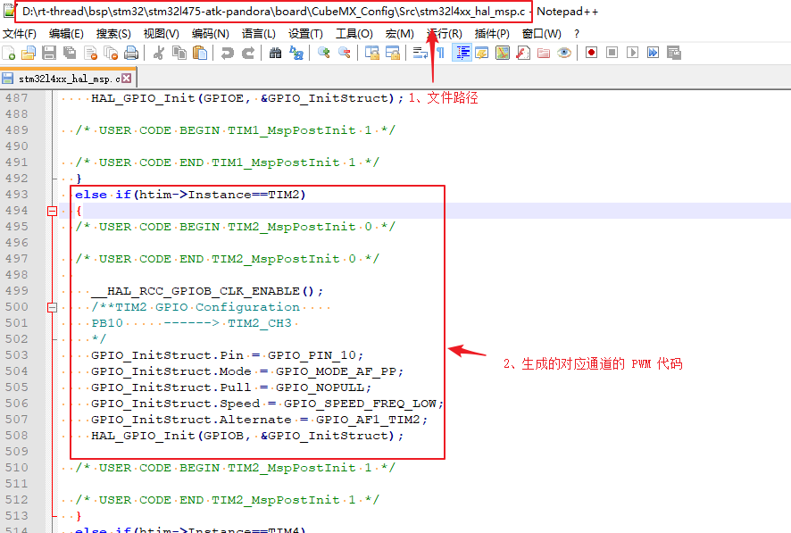
Configure Kconfig File
<span>rt-thread\bsp\stm32l475-atk-pandora\board</span> directory and add Kconfig options, as shown in the figure below:
<span>scons --target=mdk5</span> command to generate the mdk5 project, open the project and compile. If the project prompts that <span>PWMn_CONFIG</span> is undefined.<span>stm32/libraries/HAL_Drivers/config/f4/pwm_config.h</span> as shown in the figure below:
Click to read the original text to learn more about partner information