I have found that learning RTOS is a good way to learn the Linux kernel, with great potential for catching up.
-
1. Task Stack
-
1.1 Determining Task Stack Size
-
1.2 Stack Overflow Detection Mechanism
-
2. Task Status
-
3. Task Priority
-
3.1 Explanation of Task Priority
-
3.2 Task Priority Allocation Scheme
-
3.3 Difference Between Task Priority and Interrupt Priority
-
4. Task Scheduling
-
4.1 Scheduler
-
5. Critical Sections, Locks, and System Time
-
5.1 Critical Sections and Interrupt Disabling
-
5.2 Locks
-
5.3 FreeRTOS System Clock Tick and Time Management
1. Single-task System (Bare Metal)
The main approach is to use a super loop system (foreground and background system), where the application is an infinite loop that calls corresponding functions to complete respective operations, which can be seen as background behavior; interrupt service routines handle asynchronous events, which can be seen as foreground behavior. The background can also be referred to as task level, while the foreground can be referred to as interrupt level.
There are two programming approaches for the foreground and background system: polling method (real-time performance is not guaranteed, urgent and non-urgent messages cannot be effectively managed), and interrupt method (can guarantee certain real-time performance, urgent messages can be responded to).
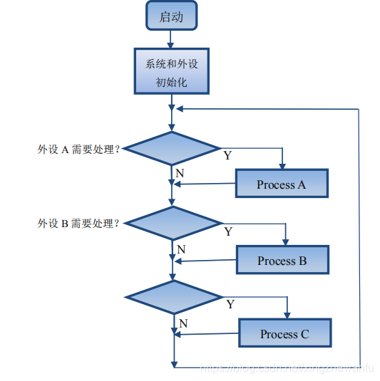
Using a combination of interrupts and polling can solve most bare metal applications, but as the complexity of the project increases, the disadvantages of the bare metal approach become apparent:
-
Must handle time-critical calculations within interrupts (ISR):
-
ISR functions become very complex and require long execution times. -
ISR nesting can lead to unpredictable execution times and stack requirements.
-
Data exchange between the super loop and ISR is done through global shared variables:
-
The application programmer must ensure data consistency.
-
Super loop can easily synchronize with the system timer, but:
-
If the system requires multiple different cycle times, it becomes difficult to implement. -
Time-consuming functions that exceed the super loop cycle need to be split. -
Increases software overhead, making the application difficult to understand.
-
Super loop makes the application very complex and therefore difficult to scale:
-
A simple change can produce unpredictable side effects, and analyzing such side effects is very time-consuming. -
The disadvantages of the super loop concept can be solved by using a real-time operating system (RTOS).
2. Multi-task System (With OS)
Using a multi-task system can address the four major disadvantages encountered in bare metal development.
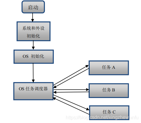
The key to implementing RTOS lies in the OS task scheduler, which uses relevant scheduling algorithms to determine which task needs to be executed currently. FreeRTOS is a real-time operating system that supports multi-tasking, with time-slice, preemptive, and cooperative scheduling modes. Through FreeRTOS, program functions can be divided into independent tasks with reasonable scheduling methods.
1. Task Stack
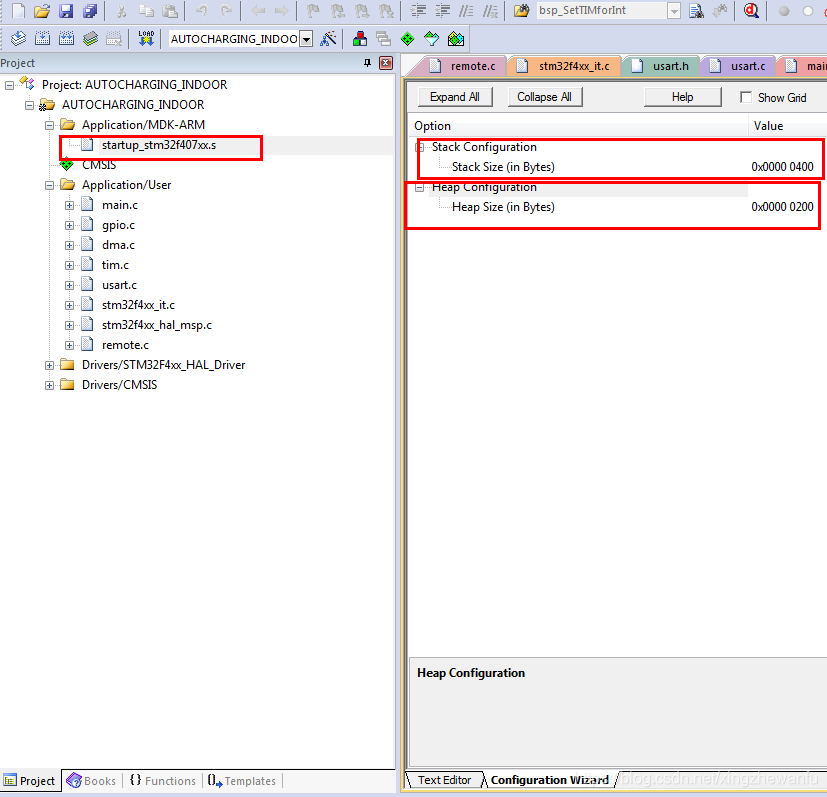
Stack size 0x400 = 1024, in bytes. In RTOS, the stack size set in the screenshot above is referred to as system stack space, while the task stack does not use this space. Where is this stack space used? In fact, it is used by interrupt functions and interrupt nesting.
Since the Cortex-M3 and M4 cores have dual stack pointers, the MSP main stack pointer and the PSP process stack pointer, or the PSP task stack pointer can also be used. In the FreeRTOS operating system, the main stack pointer MSP is used for system stack space, while the process stack pointer PSP is used for task stack. In other words, in FreeRTOS tasks, all stack space usage is pointed to by the PSP pointer. Once entering an interrupt function and possible interrupt nesting, the MSP pointer is used. This knowledge should be remembered; you may not know why now, but you must remember it. In practical applications, the allocation of system stack space depends mainly on the possible number of interrupt nesting levels. Below we will consider the worst-case execution scenario where all registers need to be stacked: 64 bytes: For the Cortex-M3 core and the Cortex-M4 core that does not use the FPU (Floating Point Unit) function, when an interrupt occurs, all 16 general-purpose registers need to be stacked, each register occupying 4 bytes, which means 16*4 = 64 bytes of space. The number of possible interrupt nesting levels would be 64 multiplied by the number of nesting levels. Of course, this is the worst-case execution scenario, meaning all registers are stacked. (Note: If an interrupt occurs during task execution, 8 registers are automatically stacked, and this stack is the task stack; when entering an interrupt, the remaining registers are stacked, and interrupt nesting uses the system stack.)
200 bytes: For the Cortex-M4 core with FPU functionality, if floating-point operations are performed in the task, when an interrupt occurs, in addition to the 16 general-purpose registers needing to be stacked, 34 floating-point registers also need to be stacked, which means (16+34)*4 = 200 bytes of space. Again, this is the worst-case execution scenario, meaning all registers are stacked.
1.1 Determining Task Stack Size
-
Calculating the function’s stack size can be quite complicated, so is there a simple way to calculate it? Yes, generally, IDE development environments have such functionality; for example, MDK generates an HTML file through which users can know the maximum stack requirement of each called function and the calling relationship between functions. However, MDK cannot determine the stack requirement when function calls are implemented via function pointers. Additionally, the stack space required for context protection during interrupts or interrupt nesting will not be accounted for. -
Generally speaking, users can pre-allocate a large stack space for the task and then print the task stack usage; running for a while will give a rough range. This method is relatively simple and practical.
1.2 Stack Overflow Detection Mechanism
The stack grows from high addresses to low addresses (M4 and M3 are in this manner).
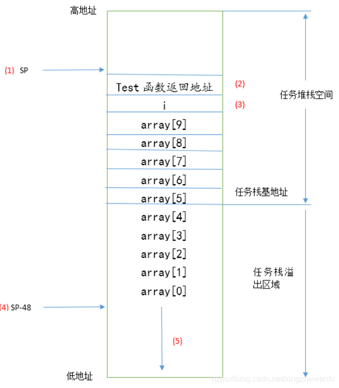
The position marked 3 in the above figure is the stack space occupied by the local variable int i and int array[10], but after allocating stack space, it has already gone out of bounds. This is what is referred to as stack overflow. If the user modifies the out-of-bounds data in the array array in the test function and this out-of-bounds stack space is temporarily unused or the data is not very important, the situation is not too serious. However, if critical data is stored, it will directly lead to system crashes.
The position marked 4 in the above figure is the local variable that allocated stack space, and the stack pointer moves down (return address + variable i + 10 array elements) * 4 = 48 bytes.
The position marked 5 in the above figure may be other tasks’ stack space or global variables or other storage areas for other purposes. If the test function uses stack space, it will allocate from here. This out-of-bounds space is temporarily unused or the data is not very important, so the situation is not too serious, but if critical data is stored, it will directly lead to system crashes.
FreeRTOS provides two stack overflow detection mechanisms, both of which are only performed during task switching:
-
During task switching, it checks whether the task stack pointer is out of bounds. If it is out of bounds, it will trigger the stack overflow hook function during task switching. void vApplicationStackOverflowHook(TaskHandle_t xTask, signed char *pcTaskName); Users can perform some processing in the hook function. This method cannot guarantee that all stack overflows will be detected. For example, if a stack overflow occurs during task execution and before task switching, the stack pointer is restored to a normal level, this situation cannot be detected during task switching. Another example is if the stack overflows, and the data in this stack area is modified, if the data in this stack area is not important or temporarily unused, it is fine, but if important data is modified, it will directly lead to hardware exceptions; in this case, the stack overflow detection function will also not detect.
Using method one requires users to configure the following macro definition in FreeRTOSConfig.h:
#define configCHECK_FOR_STACK_OVERFLOW 1
-
When creating a task, all task stack data is initialized to 0xa5. When checking the task stack during task switching, it checks whether the last 16 bytes are all 0xa5 to detect whether the task stack has overflowed. Compared to method one, this method is slightly slower, but it effectively avoids some situations in method one. However, it still cannot guarantee that all stack overflows can be detected, for example, if the last 16 bytes of the task stack are unused, not modified, but the task stack has already overflowed, this situation cannot be detected. Additionally, if the task stack overflows and the last 16 bytes of the task stack are not modified, but the data in the overflowed stack area is modified, if this data is important, it will directly lead to hardware exceptions; in this case, the stack overflow detection function will also not detect.
Using method two requires users to configure the following macro definition in FreeRTOSConfig.h:
#define configCHECK_FOR_STACK_OVERFLOW 2
In addition to the two stack overflow detection mechanisms provided by FreeRTOS, there are other stack overflow detection mechanisms that can be learned from the following blog published by Micrium: https://www.micrium.com/detecting-stack-overflows-part-2-of-2/
2. Task Status
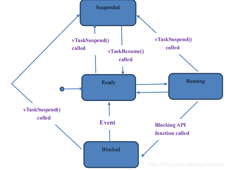
FreeRTOS task statuses (4 types): 1. Running 2. Ready 3. Blocked 4. Suspended
uCOS task statuses (5 types): 1. Sleep state 2. Ready state 3. Waiting state 4. Interrupt service state 5. Execution state
-
Running—Running State
When a task is in the actual running state, it is referred to as the running state, meaning that the CPU’s usage rights are occupied by this task.
-
Ready—Ready State
A task in the ready state is one that can run (not blocked or suspended), but is currently not running because another task of the same or higher priority is running.
-
Blocked—Blocked State
The state due to waiting for semaphores, message queues, event flag groups, etc., is referred to as the blocked state. Additionally, tasks calling delay functions will also be in the blocked state.
-
Suspended—Suspended State
Similar to the blocked state, a task can be suspended by calling the function vTaskSuspend(). Once suspended, this task will not be executed until the function xTaskResume() is called to restore it from the suspended state.
3. Task Priority
3.1 Explanation of Task Priority
-
The highest task priority in FreeRTOS is configured through the macro configMAX_PRIORITIES in the FreeRTOSConfig.h file. The actual priority range available to users is from 0 to configMAX_PRIORITIES – 1. For example, if we configure this macro to 5, then the priority numbers available to users are 0, 1, 2, 3, 4, not including 5. Beginners should pay special attention to this. -
The smaller the user-configured task priority value, the lower the priority of this task; the idle task has a priority of 0. -
It is recommended that users do not exceed a maximum value of 32 for the macro definition configMAX_PRIORITIES, meaning the user task priority range is from 0 to 31.
3.2 Task Priority Allocation Scheme
-
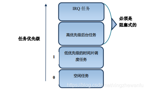
IRQ tasks: IRQ tasks are those triggered by interrupt service routines; these tasks should be set to the highest priority among all tasks. -
High-priority background tasks: Tasks such as key detection, touch detection, USB message processing, serial message processing, etc., can be categorized as this type of task. -
Low-priority time-slice scheduling tasks: Tasks such as emWin interface display, LED digital tube display, etc., that do not require real-time execution can be categorized as this type of task. In practical applications, users do not have to rigidly set all these tasks to priority 1 of the same priority; multiple priorities can be set, as long as it is noted that these tasks do not require high real-time performance. -
Idle task: The idle task is a system task.
Special note: IRQ tasks and high-priority tasks must be set to blocking (by calling message waiting or delay functions, etc.), only then will high-priority tasks release CPU usage rights, allowing low-priority tasks the opportunity to execute. This priority allocation scheme is a recommended approach; actual projects may not adopt this method. The best approach is to debug and find what suits the project’s needs.
3.3 Difference Between Task Priority and Interrupt Priority
There is no relationship between the two; regardless of the interrupt priority, the interrupt priority is always higher than any task priority. That is, if a task is executing and an interrupt occurs, the interrupt service routine starts executing.
In addition, for STM32F103, F407, and F429, the smaller the interrupt priority value, the higher the priority. However, in FreeRTOS, the task priority is such that the smaller the task priority value, the lower the task priority.
4. Task Scheduling
FreeRTOS is a real-time operating system that supports multi-tasking, with time-slice, preemptive, and cooperative scheduling methods.
-
Cooperative scheduling is mainly used in resource-limited devices and is now rarely used. For this reason, cooperative scheduling will not be removed in future FreeRTOS versions, but it will not be upgraded. -
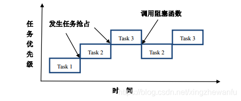
Preemptive scheduling: Each task has different priorities; tasks will run until they are preempted by a higher-priority task or encounter blocking API functions, such as vTaskDelay. -
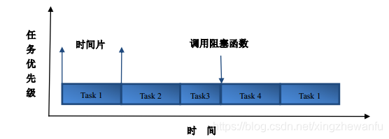
Time-slice scheduling: Each task has the same priority; tasks will run a fixed number of time slices or encounter blocking API functions, such as vTaskDelay, before switching tasks among same-priority tasks.
4.1 Scheduler
The scheduler uses relevant scheduling algorithms to determine which task needs to be executed currently. All schedulers have a common feature:
-
The scheduler can distinguish between ready tasks and suspended tasks (tasks that are suspended due to delays, waiting for semaphores, waiting for mailboxes, waiting for event groups, etc.). -
The scheduler can select one task from the ready state and activate it (by executing this task). The currently executing task is the running state task. -
The biggest difference between different schedulers is how to allocate completion time among ready tasks.
The core of an embedded real-time operating system is the scheduler and task switching, and the core of the scheduler is the scheduling algorithm. The implementation of task switching is not much different across different embedded real-time operating systems, being quite similar due to the basic hardware architecture. However, the scheduling algorithms differ somewhat.
4.1.1 Preemptive Scheduler
Using a preemptive scheduler, the highest-priority task, once ready, will always obtain control of the CPU. For example, when a running task is preempted by another high-priority task, the current task’s CPU usage rights are revoked, or it is said to be suspended; that high-priority task immediately gains control of the CPU and runs. Also, if an interrupt service routine causes a high-priority task to enter the ready state, upon completion of the interrupt, the lower-priority task that was interrupted is suspended, and the high-priority task begins running. Using a preemptive scheduler ensures that it is known when the highest-priority task can obtain control of the CPU and run, while optimizing task-level response time.
In summary, the key point to mastering preemptive scheduling is that each task is assigned a different priority, and the preemptive scheduler will run the highest-priority task from the ready list.
In FreeRTOS’s configuration file FreeRTOSConfig.h, if time-slice scheduling is disabled, then each task must be configured with a different priority. After FreeRTOS multi-tasking starts executing, it will generally execute as follows:
-
The first task to execute is the highest-priority task Task1, which will run until it encounters a blocking API function, such as a delay, at which point Task1 will be suspended, releasing the CPU execution rights for lower-priority tasks to execute. -
FreeRTOS will then continue executing the next highest-priority task from the ready list, Task2. Task2’s execution can follow two scenarios:
Task1 is restored to the ready state due to a delay, receiving a semaphore message, etc., and under the preemptive scheduler’s influence, Task2’s execution will be preempted by Task1. Task2 will run until it encounters a blocking API function, at which point it will be suspended and the next highest-priority task from the ready list will execute.
-
If the user creates multiple tasks and uses a preemptive scheduler, the execution will generally follow the two points above. According to the preemptive scheduler, the current task is either preempted by a high-priority task or releases CPU usage rights through a blocking API to allow lower-priority tasks to execute; if there are no user tasks to execute, the idle task executes.
4.1.2 Time-slice Scheduler
In small embedded RTOS systems, the most commonly used time-slice scheduling algorithm is the Round-robin scheduling algorithm. This scheduling algorithm can be used in both preemptive and cooperative multitasking. Additionally, time-slice scheduling is suitable for situations that do not require real-time task responses.
To implement the Round-robin scheduling algorithm, a specific list must be assigned to tasks of the same priority to record the currently ready tasks and assign a time slice (the length of time that needs to run; when the time slice is used up, a task switch occurs) to each task.
In FreeRTOS, only tasks of the same priority will use time-slice scheduling, and users also need to enable the macro definition in FreeRTOSConfig.h:
#define configUSE_TIME_SLICING 1
By default, this macro has already been enabled in FreeRTOS.h, so users do not need to enable it again in FreeRTOSConfig.h. Example:
-
Create 4 tasks of the same priority: Task1, Task2, Task3, and Task4. -
First, run Task1 for 5 system clock ticks, then switch to Task2 through time-slice scheduling. -
Task2 runs for 5 system clock ticks, then switches to Task3 through time-slice scheduling. -
Task3, during execution, calls a blocking API function; during this call, even if the time slice of 5 system clock ticks has not been fully utilized, it will still switch to the next task Task4 through time-slice scheduling. (Note: The unused time slice will not be reused; when Task3 is executed next time, it will still run for 5 system clock ticks.) -
Task4 runs for 5 system clock ticks, then switches back to Task1 through time-slice scheduling.
5. Critical Sections, Locks, and System Time
5.1 Critical Sections and Interrupt Disabling
A critical section of code, once execution begins, does not allow any interrupts to interrupt it. To ensure that the execution of critical section code is not interrupted, interrupts must be disabled before entering the critical section, and interrupts must be immediately enabled after executing the critical section code.
FreeRTOS has multiple critical sections in its source code; while critical sections protect the execution of critical code from being interrupted, they also affect the system’s real-time performance. For instance, if a task is calling a system API function and interrupts are disabled at this moment, meaning it has entered a critical section, if an urgent interrupt event occurs, that interrupt cannot be executed in a timely manner and must wait until interrupts are enabled to be executed. If the time interrupts are disabled exceeds the limit that urgent interrupts can tolerate, the consequences can be imagined.
FreeRTOS source code has multiple critical section handling; similar to FreeRTOS, uCOS-II and uCOS-III source codes also have critical sections, while the RTX source code does not have critical sections. Additionally, beyond the critical sections included in FreeRTOS’s source code, users also have critical section issues when writing applications, such as:
-
Code that reads or modifies variables (especially global variables used for inter-task communication) is generally the most common critical code. -
Code that calls common functions, especially non-reentrant functions, if multiple tasks access this function, the results are predictable. In short, for critical sections, the execution time should be as short as possible; otherwise, it will affect the system’s real-time performance.
Characteristics of implementing reentrant functions generally include:
The function does not have variables that persist throughout the software lifecycle (static variables). Does not reference or access variables that persist throughout the software lifecycle (global variables).
-
Task code critical section handling
In FreeRTOS task code, entering and exiting critical sections is mainly achieved by operating the basepri register. Before entering the critical section, the basepri register is operated to disable all interrupts with priority less than or equal to the macro definition configLIBRARY_MAX_SYSCALL_INTERRUPT_PRIORITY; this way, the critical section code will not be interrupted by interrupts, and the PendSV interrupt (which implements task switching) and the tick timer interrupt are the lowest priority interrupts, so during the execution of the critical section code, this task will not be interrupted by other higher-priority tasks. Upon exiting the critical section, the basepri register is reset to enable the previously disabled interrupts (here we do not consider higher-priority interrupts that are not managed by FreeRTOS).
-
Interrupt service routine critical section handling
Similar to the task code critical section handling, the handling of critical sections within interrupt service routines also has pairs of interrupt enabling/disabling functions.
5.2 Locks
-
Scheduling Lock
A scheduling lock is a function provided by the RTOS to enable or disable the scheduler; if a task calls a scheduling lock function, the code between enabling and disabling the scheduling lock will not be preempted by higher-priority tasks, meaning task scheduling is prohibited. This should be distinguished from the function of critical sections, as the scheduling lock only prohibits task scheduling and does not disable any interrupts; interrupts still execute normally. Scheduling lock-related functions;
-
Task Lock
Simply put, a lock mechanism provided to prevent the execution of the current task from being interrupted by other high-priority tasks is the task lock.
FreeRTOS does not have dedicated task lock functions, but there are two implementation methods using existing FreeRTOS functionality:
-
(1) By locking the scheduler. Utilizing FreeRTOS’s scheduling lock function to lock the scheduler will disable task switching, meaning that high-priority tasks cannot preempt the execution of low-priority tasks, and high-priority tasks also cannot switch to low-priority tasks. Additionally, it is essential to note that the scheduling lock only disables the scheduler’s operation and does not disable any interrupts. -
(2) By disabling the PendSV task switch interrupt and the Systick timer interrupt. Using FreeRTOS’s task code critical section handling functions can disable PendSV interrupt and Systick interrupt. Since before entering the critical section, the basepri register is operated to disable all interrupts with priority less than or equal to the macro definition configLIBRARY_MAX_SYSCALL_INTERRUPT_PRIORITY (the PendSV interrupt and tick timer interrupt that implement task switching are the lowest priority interrupts, so they are also disabled), this way low-priority tasks will not be interrupted by high-priority tasks during the execution of critical section code, thus achieving the effect of a task lock.
-
Interrupt Lock
An interrupt lock is a function provided by the RTOS to enable or disable interrupts; FreeRTOS does not have dedicated interrupt lock functions, but the interrupt service routine critical section handling functions can achieve the same effect.
5.3 FreeRTOS System Clock Tick and Time Management
5.3.1 FreeRTOS Clock Tick
Any operating system needs to provide a clock tick for processing time-related events such as delays and timeouts. The clock tick is a specific periodic interrupt, which can be seen as the system’s heartbeat. The time interval between interrupts depends on different applications, generally ranging from 1ms to 100ms. The clock tick interrupt allows the kernel to delay tasks for several clock ticks and provides the basis for waiting timeouts when tasks are waiting for events to occur. The faster the clock tick rate, the greater the additional overhead on the system. Any operating system needs to provide a clock tick for processing time-related events such as delays and timeouts. The clock tick is a specific periodic interrupt, which can be seen as the system’s heartbeat. The time interval between interrupts depends on different applications, generally ranging from 1ms to 100ms. The clock tick interrupt allows the kernel to delay tasks for several clock ticks and provides the basis for waiting timeouts when tasks are waiting for events to occur. The faster the clock tick rate, the greater the additional overhead on the system.
For the Cortex-M3 core STM32F103 and Cortex-M4 core STM32F407 and F429, the accompanying examples in the tutorial use the tick timer to implement the system clock tick.
5.3.2 FreeRTOS Time Management
The time management function is one of the most basic functions in FreeRTOS and is also essential to master well.
-
Time Delay
The time delay functions in FreeRTOS mainly serve the following two purposes:
Providing delays for periodically executed tasks. For preemptive schedulers, allowing high-priority tasks to release CPU usage rights through time delay functions so that low-priority tasks can execute.
The following flowchart illustrates the impact of delay functions on task running states for a clearer understanding.
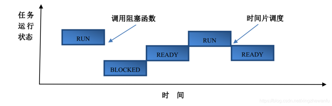
To explain the running state of Task1, the scheduler supports time-slice scheduling and preemptive scheduling. The execution process is described as follows:
-
Initially, Task1 is in the running state, and after calling the vTaskDelay function, it enters the blocked state. -
Once the delay time set by vTaskDelay elapses, since Task1 is not the highest-priority task currently ready, it cannot enter the running state and can only enter the ready state. -
After a while, the scheduler finds that Task1 is the highest-priority task currently ready, and thus the task switches from the ready state to the running state. -
Due to time-slice scheduling, Task1 switches from the running state to the ready state. FreeRTOS’s time-related functions mainly include the following four:
