IAP (In Application Programming) provides a convenient interface for product software upgrades. Users can update product software via serial port, USB, or CAN bus without using a programmer, and can even achieve remote upgrades through Ethernet or wireless networks, greatly facilitating product feature iterations and enhancing product usability.
Bootloader (hereinafter referred to as Boot) is the core that implements the IAP function. Application (referred to as App) is the user application that is responsible for implementing product functionality. Boot and App are two independent programs running on the same chip, each with its own interrupt vector table, but with the same interrupt numbers. After Boot enters App, how to ensure that the interrupts under App can respond correctly? This is a problem that all IAPs need to face, and the key to solving this problem lies in realizing the relocation of the interrupt vector. Different MCUs have significant differences in the methods of implementing interrupt vector relocation based on their own hardware characteristics.
1 Cortex-M3 Architecture MCU Interrupt Vector Relocation
The Nested Vectored Interrupt Controller (NVIC) is part of the Cortex-M core, which manages and processes all exceptions and interrupts. In Cortex-M3, the NVIC has a Vector Table Offset Register (VTOR) at address 0xE000 ED08, which allows the vector table to be relocated by modifying its value.
After entering App, as long as the VTOR register is set to the App starting address before enabling the interrupt function, the relocation of the interrupt vector table can be achieved. Reference [5] analyzes the execution process of interrupt vector relocation in Cortex-M3 microcontrollers. The Cortex-M4 core also has a VTOR register, making the implementation of interrupt vector relocation on these core MCUs very convenient and efficient.
2 Cortex-M0 Architecture MCU Interrupt Vector Relocation
The moderate performance, extremely low power consumption, and low cost make Cortex-M0 architecture MCUs widely used, especially in IoT sensors, electric tools, electronic measurement, and home appliance industries. Because the NVIC in Cortex-M0 does not have a VTOR register, interrupt vector relocation in this type of MCU becomes challenging.
2.1 STM32F030 Interrupt Vector Relocation
The STM32F030 is based on the Cortex-M0 architecture, and the manufacturer has given this series of MCUs a feature: the startup address supports remapping. By setting the chip Boot pin level, the program can start from internal Flash or internal RAM. The chip’s SYSCFG_CFGR1 register also stores the setting status, and by modifying the value of this register, the program can be rebooted.
Based on the address remapping feature, before enabling the interrupt function in App, the interrupt vector table can be copied to the starting address of internal RAM, and then the SYSCFG_CFGR1 register can be set to start from RAM, thus achieving interrupt vector relocation.
2.2 Dilemmas in Implementing IAP on Regular Cortex-M0 Architecture MCUs
Not all microcontrollers with Cortex-M0 cores support address remapping, as this is not part of the core’s functionality. There are many specialized MCUs using the Cortex-M0 core on the market, such as some dedicated MCUs for motor control. They do not have the address remapping feature like the STM32F030, so they cannot use the method in 2.1 to achieve interrupt vector relocation.
Therefore, achieving interrupt vector relocation becomes the biggest obstacle for such Cortex-M0 architecture MCUs to implement IAP functions. Relevant research materials are scarce, and reference [9] provides a RAM-based interrupt jump method, although its efficiency needs improvement.
3 General Method for Interrupt Vector Relocation
This article provides a general method for implementing interrupt vector relocation. This method does not rely on the MCU’s own hardware characteristics but is based on pure software implementation. It also details the principle of this method in combination with STM32F030 and the Keil development environment, providing relevant code.
3.1 Ladder Function
Each interrupt vector is augmented with a program responsible for obtaining the entry address of the corresponding interrupt service function in App and then jumping to that address to execute, thus running the App’s interrupt service program. This function acts like a ladder from the Boot interrupt vector to the App interrupt service function, hence it is called a “ladder function.” Each interrupt vector in the Boot interrupt vector table stores the entry address of the corresponding ladder function.
3.2 Interrupt Vector Relocation Process
Figure 1 shows the jump flow chart for interrupt vector relocation based on this method. During the App’s operation, when an interrupt occurs, it will still obtain the corresponding interrupt vector from the Boot interrupt vector table. However, at this time, the actual address obtained is the entry address of the ladder function, and then the ladder function is used to jump to the App interrupt service program.
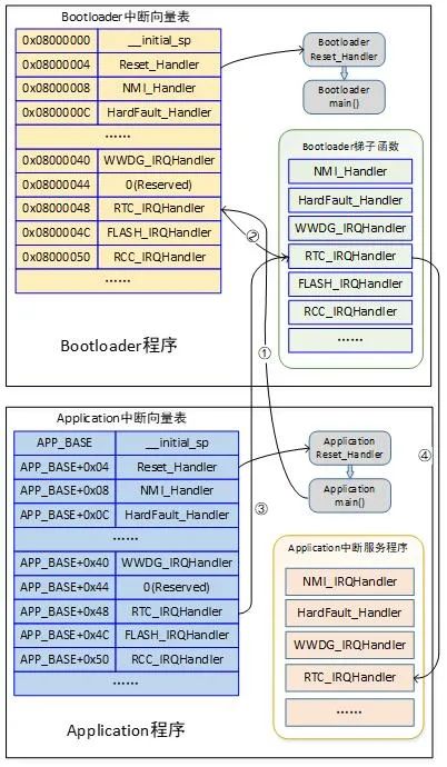
Figure 1 General Method for Interrupt Vector Table Relocation
Taking the RTC interrupt as an example, when the App generates this interrupt, it will find the entry address of the ladder function for the RTC interrupt from the Boot interrupt vector table and jump to that address, as shown by arrows ① and ②. The ladder function for the RTC interrupt will then load the entry address of the corresponding RTC interrupt service program from the App’s RTC interrupt vector, as shown by arrow ③. Finally, it jumps to that address to execute the App’s RTC interrupt service program, as shown by arrow ④.
3.3 Implementation of Ladder Functions
The ladder function is key to achieving the jump from the Boot interrupt vector to the App interrupt service program. The program is implemented in assembly code, with one ladder function corresponding to one interrupt vector. Below are examples of some ladder functions:
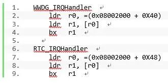
Taking RTC_IRQHandler as an example, 0x0800 2000 is the starting address of the App, corresponding to the value of APP_BASE in Figure 1. 0x48 is the offset address of the RTC interrupt vector. Line 7 loads the RTC interrupt vector offset address into the r0 register. Line 8 loads the address of the App’s RTC interrupt handler into the r1 register. Line 9 uses the bx instruction to jump to the entry point of the App’s RTC_IRQHandler interrupt service program.
By setting ladder functions for each interrupt vector in Boot, the interrupt vector table can be relocated through the bridge function of the ladder functions. The IAP function has been verified on the STM32F030 based on this method, and the interrupt functionality of the App runs normally, validating the feasibility of this method.
4 Improvement Method 1 for Interrupt Vector Relocation
4.1 Existing Problems
Each ladder function requires two ldr instructions and one bx instruction, which takes 2 and 3 instruction cycles respectively, resulting in a total of 7 instruction cycles for one ladder function. Additionally, the clock frequency of Flash is generally much lower than that of the CPU. For example, when the CPU clock frequency of STM32F030 exceeds 24 MHz, accessing Flash requires inserting a wait cycle.
In summary, entering the App interrupt service function incurs a significant time overhead. When interrupts need to respond quickly or there are high-frequency interrupts such as ADC sampling, this method of interrupt vector relocation can lead to a noticeable performance degradation of the system, necessitating improvements to the interrupt vector relocation method.
4.2 Improvement Principle
The improvement is divided into two aspects: one is to reduce the instructions required for the ladder function, and the other is to move the ladder function to run in internal RAM.
Both Boot and App have a copy of the ladder function for interrupt vector relocation. The ladder function in Boot is used for interrupt vector relocation without speed requirements, and its working principle and execution effect are the same as described earlier. The ladder function in App is for interrupt relocation of interrupts that require reduced response latency and improved interrupt handling performance. The execution process of the interrupt vector table relocation in Improvement Method 1 is shown in Figure 2.
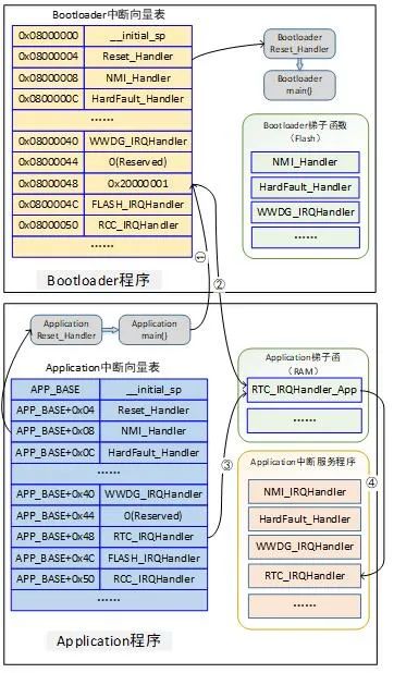
Figure 2 Execution Process of Interrupt Vector Table Relocation in Improvement Method 1
Still taking RTC_IRQHandler as an example, at this time, the ladder function for this interrupt vector, RTC_IRQHandler_App, is located in RAM, with a fixed address of 0x2000 0001. Meanwhile, the corresponding unit in Boot for the RTC_IRQHandler interrupt vector stores this address. When the RTC interrupt occurs during the App’s operation, the MCU will obtain the address 0x2000 0001 from the RTC_IRQHandler interrupt vector in Boot and jump to the entry point of the RTC interrupt ladder function in App, as indicated by arrows ① and ②. The ladder function will obtain the address of the RTC_IRQHandler interrupt service function from the App’s interrupt vector table, as indicated by arrow ③, and finally jump to the entry point of the App’s RTC interrupt service program, as indicated by arrow ④.
4.3 Ladder Functions in App
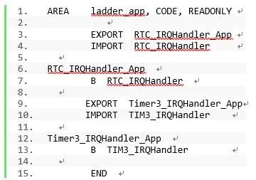
Examples of ladder functions used in App are as follows:
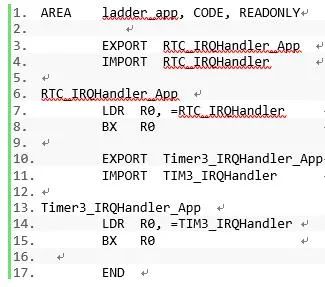
In this example, Line 1 defines a code segment named “ladder_app.” Line 6 defines the RTC_IRQHandler_App function, consisting of two assembly instructions. First, it loads the address of the RTC_IRQHandler interrupt service function in App into the R0 register, and then jumps to that address to execute. Compared to before the improvement, it only requires LDR and BX instructions, totaling only 5 instruction cycles. Furthermore, this code runs in RAM, unaffected by Flash wait cycles.
4.4 Distributed Loading Settings in App
Through distributed loading, the ladder function in the App can always be located at a fixed address in RAM, independent of the specific application program. The distributed loading file for STM32F030 in Keil is as follows:
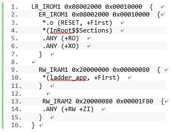
Line 10 loads the “ladder_app” code segment to address 0x2000 0000, with a length of 128 bytes. If there are many ladder functions in the App, the reserved space needs to be increased accordingly, and vice versa.
The entry address of the ladder function can be obtained from the map file after the project is compiled successfully. As shown in Figure 3, the entry address of the RTC_IRQHandler_App function is 0x2000 0001, which is the source of the address stored in the RTC_IRQHandler vector in Boot.
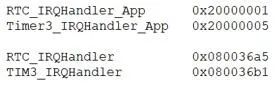
Figure 3 Ladder Function and Interrupt Service Function Entry Address
5 Improvement Method 2 for Interrupt Vector Relocation
The previous section discussed moving the ladder function to run in RAM, significantly reducing the time overhead of entering the user interrupt service program. This section discusses further improvements to compress the time overhead of ladder functions and enhance the efficiency of entering interrupt programs.
5.1 Improvement of Ladder Functions
The improved ladder function code is as follows:
It can be seen that only one B instruction is needed to jump to the entry of the interrupt service function. This instruction takes only 3 clock cycles to execute, further reducing the time overhead required for the ladder function to run.
The B instruction is a relative jump instruction used for unconditional jumps, supporting a jump address range of PC-2046 to PC+2046. Therefore, the interrupt service function must also be located in internal RAM and within 2046 bytes of the corresponding ladder function jump instruction address. This condition is easily met, as not all interrupt service functions need to do this; only a few time-sensitive, high-frequency interrupts need to be handled in this manner.
5.2 Constraints on Interrupt Service Functions
To achieve the address constraints of interrupt handling functions, constraints attributes need to be added when writing the relevant interrupt handling functions. By setting the section attribute for the function, the interrupt service program can be placed in a custom input segment named “ramfunc_isr.” Apart from this, there is no other difference from ordinary interrupt handling functions. For example, in the Keil environment, the RTC interrupt handling function is written as follows:
5.3 Distributed Loading File
The distributed loading file settings for Improvement Method 2 are as follows:
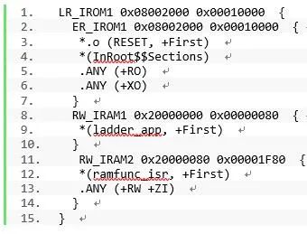
Compared to the distributed loading file for Improvement Method 1, it adds Line 12, which places the contents of the “ramfunc_isr” segment starting from address 0x2000 0080.
Figure 4 shows part of the contents of the map file, where the entry address of the ladder function RTC_IRQHandler_App is 0x2000 0001, and the entry address of Timer3_IRQHandler_App is 0x2000 0003. At this time, the size of the storage space occupied by a ladder function in the App is only 2 bytes. The actual entry addresses of the interrupt handling functions are 0x200 00081 and 0x2000 008d, both located in RAM, immediately following the ladder functions, with relative addresses far less than 2046 B, meeting the usage requirements of this improvement method.
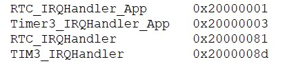
Figure 4 Ladder Function and Interrupt Service Function Entry Address
6 Conclusion
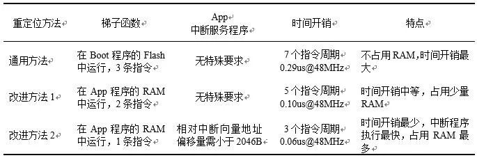
Table 1 compares the general method for interrupt vector relocation proposed in this article and its two improvement methods, summarizing the characteristics of the three methods. In fact, the three methods can be used in combination. For example, use Improvement Method 2 for the high-frequency ADC sampling interrupt, minimizing the additional time overhead while significantly improving performance since this interrupt service program runs in RAM. For medium-frequency timer interrupts, use Improvement Method 1 for interrupt vector relocation, while using the general method for other ordinary interrupt vectors.
Table 1 Comparison of Three Methods for Interrupt Vector Relocation
Based on the interrupt vector table relocation method proposed in this article, verification has been conducted in the STM32F030 and Keil development environment, and the results are correct. In addition, verification has also been carried out on other brands of MCUs based on the Cortex-M0 core, achieving success as well. Currently, the IAP function implemented based on this method has been used in products in bulk, with good results.
Although the method of interrupt vector relocation proposed in this article is discussed and tested with the Cortex-M0 core MCUs, it does not rely on the special characteristics of the hardware, so it can also be promoted and applied to other core MCUs.
References
[1] Wang Yize, Cai Hong. Design and Implementation of IAP Based on CAN Bus for AVR Microcontroller [J]. Electronic Technology, 2018(1):57-60.
[2] Shi Pan, He Dongwei, Xu Boming. Research on IAP Remote Upgrade Technology Based on LWIP [J]. Mechatronics, 2017(5):31-34.
[3] Luo Jingjing. Design and Implementation of Remote Upgrade System for Embedded Devices Based on 4G Network [D]. Changchun: Jilin University, 2021:1-2.
[4] Joseph Yiu. Cortex-M3 Authority Guide [M]. Song Yan, Trans. Beijing: Beijing Aerospace University Press, 2009:83-107.
[5] Ma Jian, Huang Zengbo, Li Zefang. Research on Online Upgrade Technology of Coal Mine Safety Monitoring System Sensors [J]. Coal Mine Safety, 2022(4):136-137.
[6] Fan Yunlong, Fang Anping, Li Ning. Initial Exploration of Cortex-M0 Processor [J]. Microcontroller and Embedded System Applications, 2010(6):78-81.
[7] STMicroelectronics. Reference manual STM32F030, 2017:144-146.
[8] Joseph Yiu. ARM Cortex-M0 Authority Guide [M]. Wu Changyu, et al. Trans. Beijing: Tsinghua University Press, 2013:104-105.
[9] Han Yuhong, Chen Liangyong. Method for Implementing IAP and APP Interrupts in Microcontrollers without Interrupt Vector Relocation [J]. Information Technology and Network Security, 2020(2):53-56.
[10] STMicroelectronics. Cortex-M0 Technical Reference Manual, 2009.
[11] STMicroelectronics. STM32F030x Datasheet, 2013.
(This article is authorized for publication by the Journal of Microcontrollers and Embedded System Applications, originally published in the 2023 issue 9)