Click the card below to follow Arm Technology Academy
This article is authorized to be reproduced from the WeChat official account Pi Zi Heng Embedded. Using the NXP i.MXRT1170 model as an example, this article introduces the method of redirecting the interrupt vector table.
In embedded code design, sometimes certain special operations (such as Flash erase under XIP, low-power mode switching) cannot be interrupted at will, or some shared data areas cannot be accessed disorderly (Task A is reading while Task B wants to write). In these cases, we can use the system global interrupt switch control to achieve what is called critical section protection.
However, in some scenarios, switching off the system global interrupts is not always effective. For example, in the case of Flash erase under XIP, if there is a background timer (like SysTick) running in real-time, turning off the system global interrupts during the Flash erase (which may take a long time) will prevent the timer interrupt from responding, causing system timing deviations. Clearly, we cannot turn off the system global interrupts in this situation.
To ensure that the system can still respond promptly to timer interrupts (executing interrupt handler functions) during Flash erase, we need to link the timer interrupt handler function and its related code to RAM for execution, and we also need to redirect the interrupt vector table to RAM. Today, let’s talk about the method of redirecting the interrupt vector table:
1 Introduction to the Cortex-M Interrupt Vector Table
Friends familiar with the Arm Cortex-M processor should be aware of the following table, which is the interrupt vector table. Each vector in the table is 4 bytes in size, and except for the 0th vector, the rest are function addresses. This table centrally stores the addresses of all system interrupt handler functions (xxxIRQHandler).
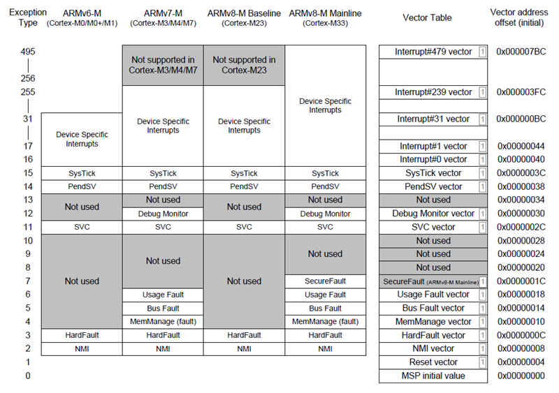
For MCUs with embedded Flash, the initial interrupt vector table is generally required to be fixed linked to the starting address of Flash, because the system startup always retrieves the 0th (initial stack) and 1st vector (initial PC, reset function ResetHandler) from the starting address of Flash to begin executing application code. For some MCUs with BootROM or without internal Flash, the initial interrupt vector table may be placed at other addresses in Flash, depending on the specific chip design.
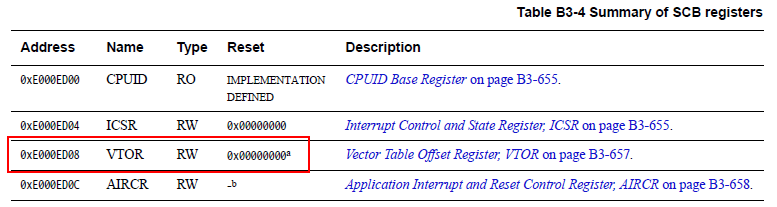
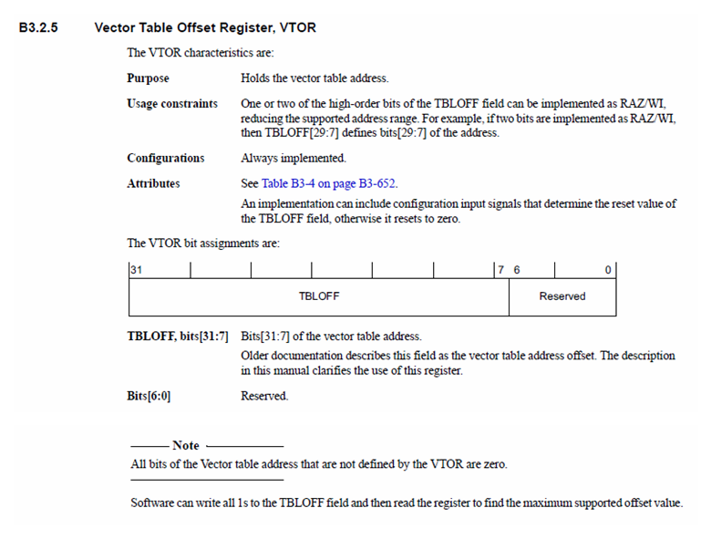
Once the application program is running, if an interrupt occurs, the system will find the corresponding peripheral interrupt handler function in the interrupt vector table based on the interrupt number issued by the requesting peripheral and execute it. The Cortex-M core (except for CM0) has a dedicated VTOR register in the SCB module to control the starting address of the interrupt vector table (note that the address needs to be 128 bytes aligned). After the program starts running, users can configure the SCB->VTOR register to reset the interrupt vector table address.
2 Method of Redirecting the Interrupt Vector Table
Now we will introduce the method of redirecting the interrupt vector table using the NXP i.MXRT1170 model as an example, demonstrated in the \\SDK_2.9.1_MIMXRT1170-EVK\\boards\\evkmimxrt1170\\demo_apps\\led_blinky\\cm7\\iar project.
2.1 Files Related to the Interrupt Vector Table
In this led_blinky project, there are two files related to the interrupt vector table: one is startup_MIMXRT1176_cm7.s startup file, which contains the entity definition of the interrupt vector table and the reset function ResetHandler(). From the reset function, you can see that it first resets the SCB->VTOR register.
        THUMB
        PUBWEAK Reset_Handler        SECTION .text:CODE:REORDER:NOROOT(2)Reset_Handler        CPSID   I               ; Mask interrupts        LDR     R0, =0xE000ED08      ; SCB->VTOR        LDR     R1, =__vector_table  ; section .intvec segment start address        STR     R1, [R0]        LDR     R2, [R1]        MSR     MSP, R2        LDR     R0, =SystemInit        BLX     R0        CPSIE   I               ; Unmask interrupts        LDR     R0, =__iar_program_start        BX      R0
The value of __vector_table used in the reset function is determined by the following statement set in the MIMXRT1176xxxxx_cm7_flexspi_nor.icf linker file. Since the i.MXRT1170 does not have internal Flash, the system mapping starting address allocated to the external NOR Flash (connected to the FlexSPI1 peripheral) is 0x30000000, while 0x30002000 is one of the application initial interrupt vector table addresses supported by BootROM (indicated in the IVT startup header).
define symbol m_interrupts_start       = 0x30002000;define symbol m_interrupts_end         = 0x300023FF;
define exported symbol __VECTOR_TABLE          = m_interrupts_start;
place at address mem: m_interrupts_start    { readonly section .intvec };
After compiling the project, you can find the final linked address of the initial interrupt vector table in the corresponding generated iledblinky_cm7.map mapping file. For ease of subsequent problem analysis, we also list the timer interrupt handler function addresses:
********************************************************************************** PLACEMENT SUMMARY***
"A0":  place at address 0x3000'2000 { ro section .intvec };
  Section              Kind         Address    Size  Object  -------              ----         -------    ----  ------"A0":                                         0x400  .intvec              ro code  0x3000'2000   0x400  startup_MIMXRT1176_cm7.o [1]                              - 0x3000'2400   0x400
********************************************************************************** ENTRY LIST***
Entry                       Address   Size  Type      Object  -----                       -------   ----  ----      ------SysTick_Handler         0x3000'5767   0x10  Code  Gb  led_blinky.o [1]__VECTOR_TABLE {Abs}    0x3000'2000         Data  Gb  <internal module>__Vectors               0x3000'2000          --   Gb  startup_MIMXRT1176_cm7.o [1]__Vectors_End           0x3000'2400         Data  Gb  startup_MIMXRT1176_cm7.o [1]__Vectors_Size {Abs}          0x400          --   Gb  startup_MIMXRT1176_cm7.o [1]__vector_table          0x3000'2000         Data  Gb  startup_MIMXRT1176_cm7.o [1]
2.2 Example of Interrupt Redirection Function
The timer interrupt handler function SysTick_Handler() linked in Flash is clearly not feasible. We use IDE features (for IAR, it is the __ramfunc modifier) to link it to RAM (the MIMXRT1176xxxxx_cm7_flexspi_nor.icf defines the TEXT2_region:0x0-0x3FFFF space for storing section.textrw segments), recompile the project, and check the mapping file to see that the new allocated address is 0x1.
printf("hello world!");********************************************************************************** ENTRY LIST***
Entry Address Size Type Object ----- ------- ---- ---- ------SysTick_Handler 0x1 0x14 Code Gb led_blinky.o [1]Now we try to manually relocate the interrupt vector table in the code by finding a free RAM area (such as 0x20000000-0x200003FF) and directly copying the contents of the interrupt vector table there. The sample code is as follows. The main function calls this relocate_vector_table() function at the beginning, and everything runs normally after downloading the modified project to the board, indicating that the interrupt vector table redirection operation was successful.
extern uint32_t __VECTOR_TABLE[];
void relocate_vector_table(void){    __disable_irq();    // Copy the initial interrupt vector table from 0x30002000 to the new address 0x20000000    memcpy((void *)0x20000000, (void *)__VECTOR_TABLE, 0x400);    // Set VTOR to point to 0x20000000    SCB->VTOR = 0x20000000;    __enable_irq();}
int main(void){    relocate_vector_table();
    // Other code}
Recommended Reading
-
Arm Expands Cortex-M Product Line, Bringing AI to Ultra-Small Endpoint Devices
-
Special Considerations for Using FreeRTOS with Cortex-M Cores
-
Can Cortex-M Microcontrollers Run Linux Operating Systems?


Long press to recognize the QR code to add Miss Jishu WeChat (aijishu20) and join the Arm Embedded Developer Group.
Follow Arm Technology Academy
 Click the button below “Read the Original“, to read more articles in the Embedded Inn’s column.