
Click the blue text to add “Star Mark ★” to follow us
1
Introduction to MM32F5330 MPU
Dynamic Microelectronics has released a new high-performance MM32F5 microcontroller series equipped with the Anmou Technology “Star” STAR-MC1 processor. This series features innovations in core, bus, and peripheral configurations, and for the first time, it is equipped with the Armv8-M architecture “Star” STAR-MC1 processor. Compared to the Armv7-M architecture, the Armv8-M architecture not only significantly improves performance but also enhances security: the Armv8-M architecture introduces TrustZone technology and strengthens the Memory Protection Unit (MPU), allowing code to run in a more secure environment.
The MPU defines protected regions in a 4GB address mapping. The MPU on Armv8-M has 8 regions, each with a starting address, ending address, access permissions, and memory attributes, with each region having its own attributes. Unlike the previous Armv7-M MPU, the Armv8-M MPU does not support region overlap; if an address appears in two different regions, it will cause a HardFault. If a program accesses a memory location prohibited by the MPU, the processor will generate a MemManage exception.
The MPU is essentially designed to protect a segment of address space from being accessed by unauthorized programs. Typically, embedded operating systems use the MPU for memory protection, allowing the kernel to dynamically update MPU region settings based on processes. The MPU can make embedded systems more robust and protect certain encrypted areas. The MPU has the following capabilities to enhance system robustness:
It can prevent users from corrupting data needed by the operating system.
It can prevent one task from illegally accessing another task’s data, completely isolating tasks.
It can set critical data areas as read-only to prevent corruption.
It can detect other unexpected accesses, such as stack overflows and array out-of-bounds.
2
Memory Types
In Armv8, memory is divided into two types: Normal memory and Device memory. Normal memory is suitable for most memory in the system, while Device memory is used for memory utilized by peripherals.
Normal memory mainly refers to RAM, ROM, FLASH, etc. The processor and compiler can optimize programs, and the processor can also perform operations like repeat, reorder, and merge. In cases of enforced access order, memory barrier instructions need to be called.
Device memory typically corresponds to memory mapping for peripherals. Device types are used in locations that may have side effects, are non-cacheable, and do not allow speculative data access to regions marked as Device.
Device memory attributes:
1) G: Gather, multiple memory accesses can be merged.
2) R: Reordering, reordering memory access instructions.
3) E: Early Write Ack, write operation acknowledgment can be responded to early.
Four types of Device memory:
1) Device nGnRnE, does not allow gather, reorder, or early.
2) Device nGnRE, allows early.
3) Device nGRE, allows reorder and early.
4) Device GRE, allows gather, reorder, and early.
The table below shows possible MPU region attributes, including Shareable and Cacheable attributes.
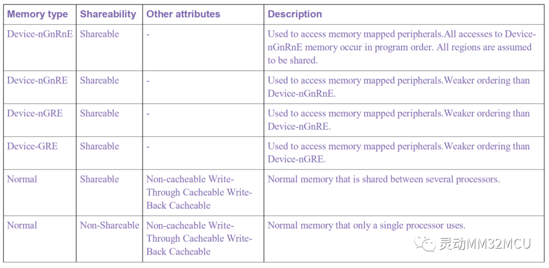
There are many details regarding Armv8 memory types and attributes, and configuring MPU region attributes will involve cache read/write strategies. Interested readers can refer to relevant materials for a detailed understanding. In this chapter, we focus on understanding the functions and roles of the MPU and perform simple validations; details about cache content will be explained in subsequent chapters.
3
MPU Register Module
3.1 The MPU has the following main registers
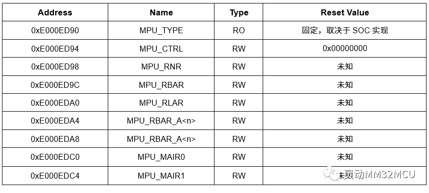
3.2 MPU_TYPE
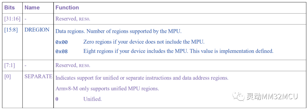
The MPU_TYPE register indicates whether the MPU exists and how many regions it supports.
3.3 MPU_CTRL
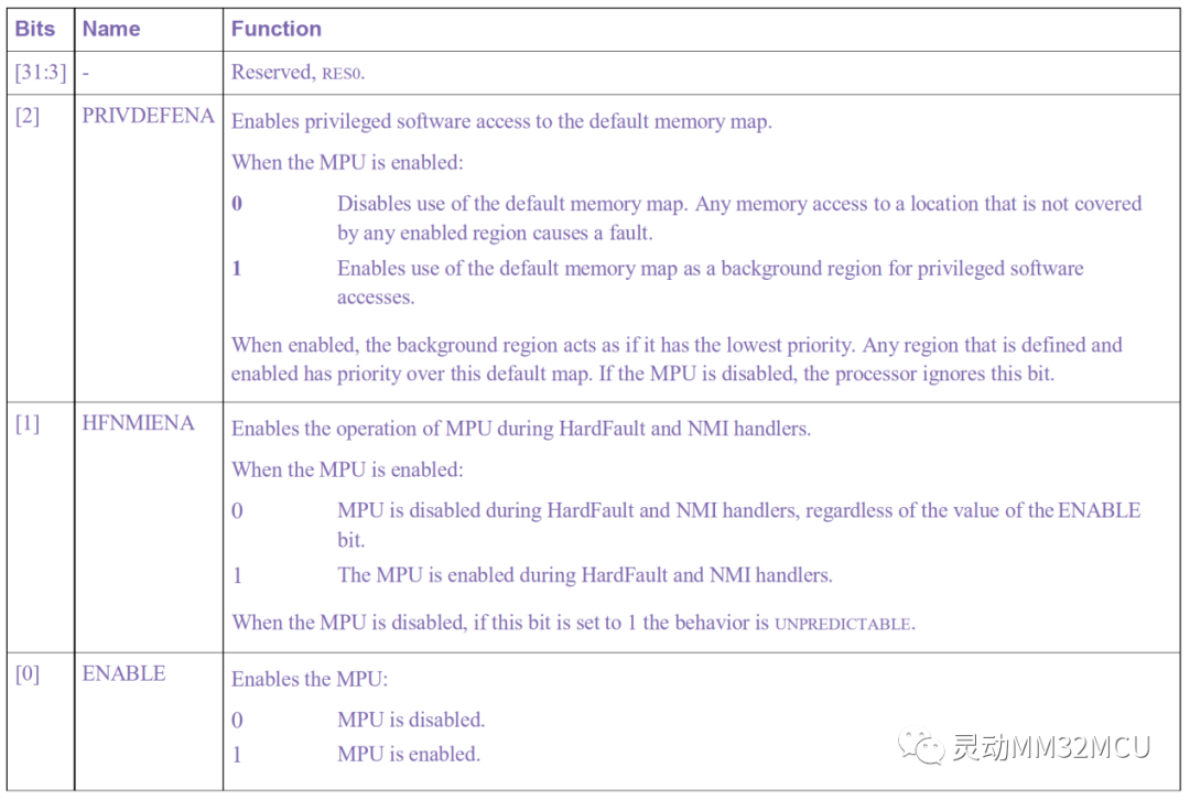
MPU_CTRL is used to enable the MPU, enable the background map, and enable whether the MPU is effective in NMI.
3.4 MPU_RNR
MPU_RNR is used to select a region. Before accessing MPU_RBAR and MPU_RLAR, MPU_RNR must be written to select the region.

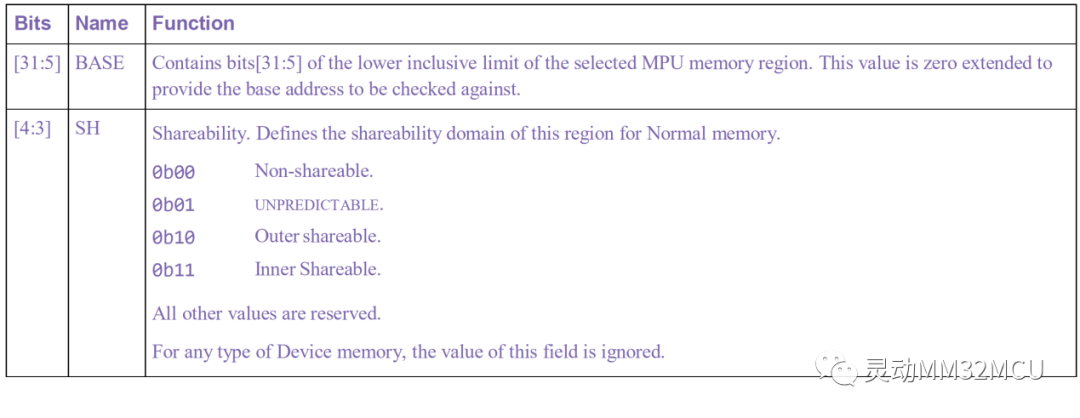
3.5 MPU_RBAR
MPU_RBAR defines the starting address of the region.

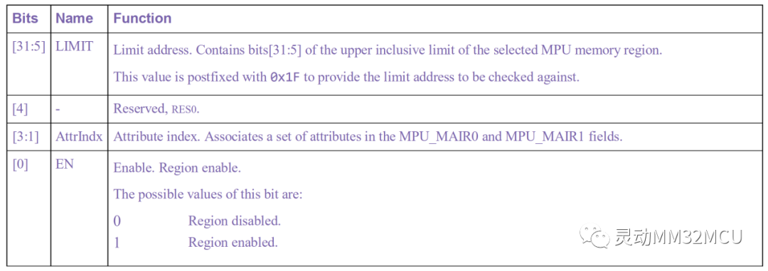
3.6 MPU_RLAR
MPU_RLAR defines the upper address of the region and selects the region attributes.
3.7 MPU_MAIR0 and MPU_MAIR1
MPU_MAIR0 and MPU_MAIR1 provide memory attribute encoding corresponding to the AttrIndex value.
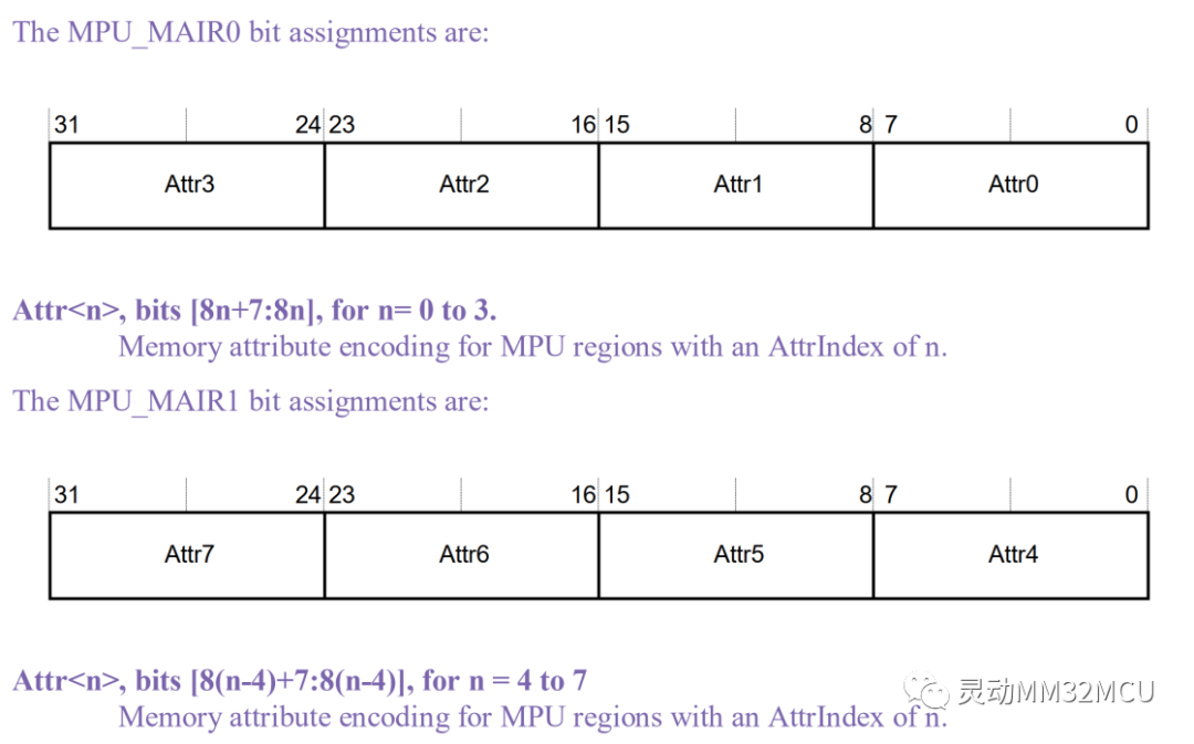
Each region attribute MARI_ATTR occupies 8 bits.
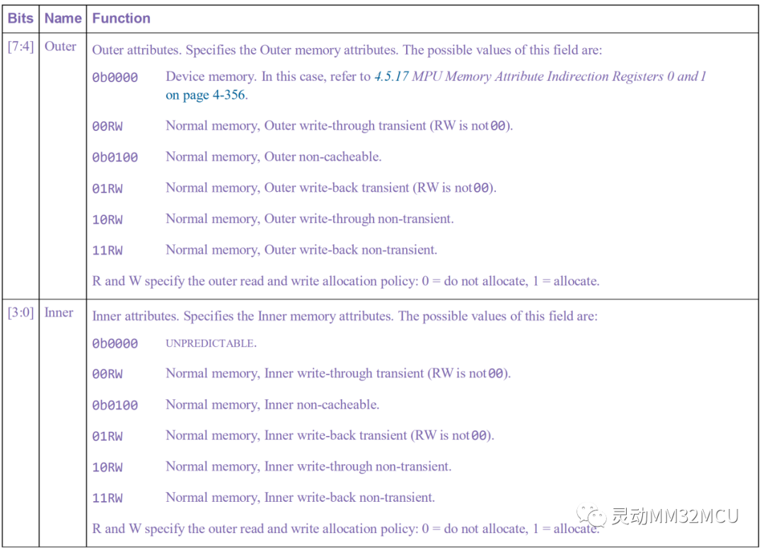
If MAIR_ATTR[7:4] is 0, then MAIR_ATTR is defined as follows:

If MAIR_ATTR[7:4] is not 0, then MAIR_ATTR is defined as follows:
4
MPU Configuration
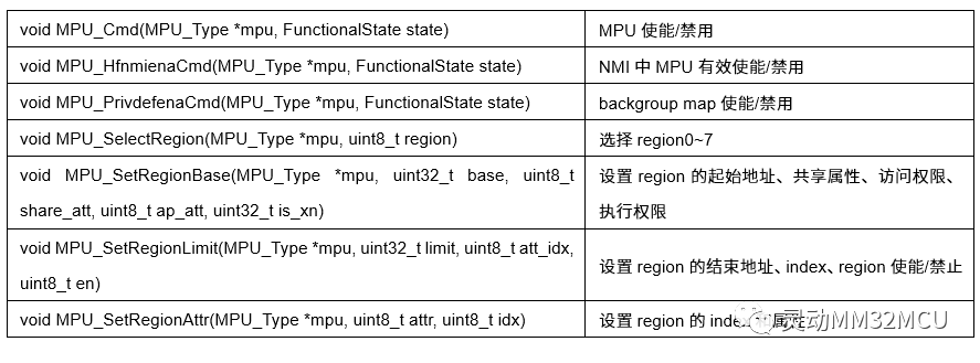
For MPU configuration, please refer to the LibSamples on the Dynamic Microelectronics official website. Specifically, the core_starmc1.h and mpu_armv8.h files define the MPU register mapping and interface functions. The following table lists some functions:
5
MPU Testing
5.1 Region Read/Write Test
Define a pointer variable pointing to address 0x20006000. When the MPU is disabled, this address can be read and written normally. By configuring the MPU to set the region 0x20006000 – 0x20006FFF as read-only, enable the MPU and then perform a write access to observe the operation. The test code is as follows:
void mpu_readwrite(void)
{
    volatile uint32_t *temptr = (volatile uint32_t *)0x20006000UL;
    MPU_Cmd(MPU, DISABLE);    //Disable MPU
    *temptr = 0x00;
    printf("%x : %x\n", (uint32_t)temptr,*temptr);
    *temptr = 0xA5;
    printf("%x : %x\n", (uint32_t)temptr,*temptr);

    //Enable MPU region0:0x20006000 - 0x20006FFF
    //Read-only,Execution not permitted,Device memory
    MPU_SelectRegion(MPU, 0);
    MPU_SetRegionBase(MPU, 0x20006000UL, REGION_NON_SHAREABLE, REGION_RO_ANY, REGION_XN);
    MPU_SetRegionLimit(MPU, 0x20006FFFUL, 0, REGION_EN);
    MPU_SetRegionAttr(MPU, 0, 0);

    MPU_HfnmienaCmd(MPU, ENABLE);
    MPU_PrivdefenaCmd(MPU, ENABLE);
    MPU_Cmd(MPU, ENABLE);

    printf("Test start:\n");
    //After MPU is enabled, check whether the write permission is granted.
    printf("%x : %x\n", (uint32_t)temptr,*temptr);
    //The hardfault will be triggered when the code is executed here.
    *temptr = 0x5A;
    printf("%x : %x\n", (uint32_t)temptr,*temptr);
    printf("Test over!\n");
}
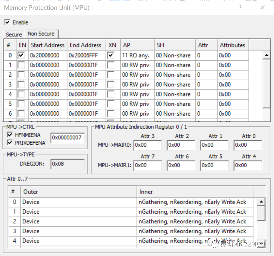
Simulation shows that the MPU configuration and code execution are consistent with expectations:
Serial port debugging assistant printout:

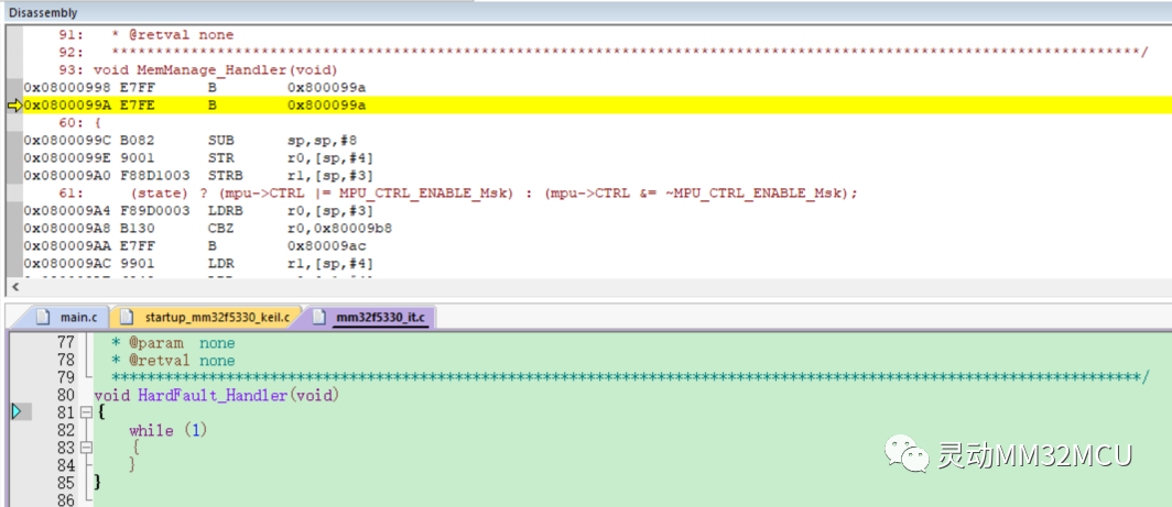
Data printed before “Test start” can be read and written. After enabling the MPU, the data can be read once, but when executing the assignment statement *temptr = 0x5A, it enters a HardFault, indicating that this address is not writable.
Modify the test code to set region0 as read/write:
    MPU_SelectRegion(MPU, 0);
    MPU_SetRegionBase(MPU, 0x20006000UL, REGION_NON_SHAREABLE, REGION_RW_ANY, REGION_XN);
    MPU_SetRegionLimit(MPU, 0x20006FFFUL, 0, REGION_EN);
    MPU_SetRegionAttr(MPU, 0, 0);
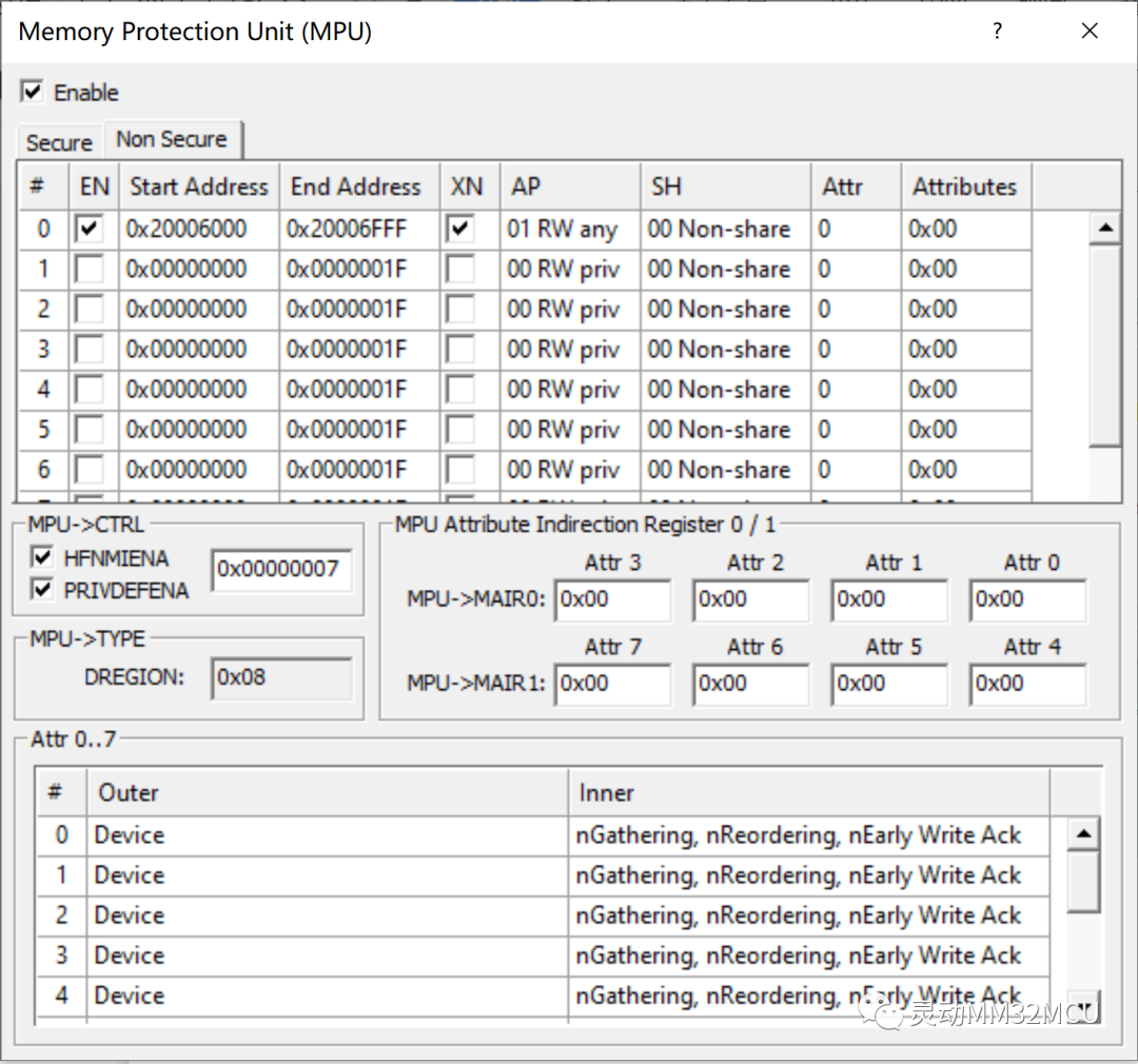
Simulation shows that the MPU configuration and code execution are consistent with expectations:
Serial port debugging assistant printout:

The test code executed completely. After enabling the MPU, the data can be read, and after executing the assignment statement *temptr = 0x5A, the printed data at that address is 0x5A, indicating that the write operation is normal.
In summary, the MPU can effectively set read/write permissions for regions.
5.2 Region Overlap Test
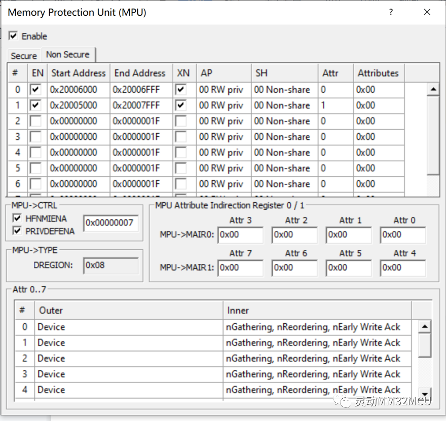
Define a pointer variable pointing to address 0x20006000. When the MPU is disabled, this address can be read and written normally. By configuring the MPU to set the region 0x20006000 – 0x20006FFF as read/write and the region 0x20005000 – 0x20007FFF as read/write, enable the MPU and then access address 0x20006000. The test code is as follows:
void mpu_overlap(void)
{
    volatile uint32_t *temptr = (volatile uint32_t *)0x20006000UL;

    MPU_Cmd(MPU, DISABLE);
    *temptr = 0x00;
    printf("%x : %x\n", (uint32_t)temptr,*temptr);
    *temptr = 0xB9;
    printf("%x : %x\n", (uint32_t)temptr,*temptr);

    //Configure region0:0x20006000 - 0x20006FFF
    //Read/write,Execution not permitted,Device memory
    MPU_SelectRegion(MPU, 0);
    MPU_SetRegionBase(MPU, 0x20006000UL, REGION_NON_SHAREABLE, REGION_RW_PRIV_ONLY, REGION_XN);
    MPU_SetRegionLimit(MPU, 0x20006FFFUL, 0, REGION_EN);
    MPU_SetRegionAttr(MPU, 0, 0);

    //Configure region1:0x20005000 - 0x20007FFF
    //Read/write,Execution not permitted,Device memory
    MPU_SelectRegion(MPU, 1);
    MPU_SetRegionBase(MPU, 0x20005000UL, REGION_NON_SHAREABLE, REGION_RW_PRIV_ONLY, REGION_XN);
    MPU_SetRegionLimit(MPU, 0x20007FFFUL, 1, REGION_EN);
    MPU_SetRegionAttr(MPU, 0, 1);

    MPU_HfnmienaCmd(MPU, ENABLE);
    MPU_PrivdefenaCmd(MPU, ENABLE);
    MPU_Cmd(MPU, ENABLE);

    printf("Test start:\n");
    //The address of the 0x20006000 overlaps in region0 and region1.
    //Accessing the address triggers a hard fault.
    printf("%x : %x\n", (uint32_t)temptr,*temptr);
    printf("Test over!\n");
}
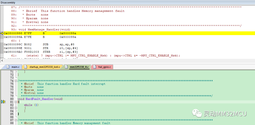
Simulation shows that the MPU configuration and code execution are consistent with expectations:
Serial port debugging assistant printout:

Data printed before “Test start” can be read and written. After enabling the MPU, since address 0x20006000 is in the overlap region of region0 and region1, executing the print statement *temptr triggers a HardFault, indicating that this location is not accessible, demonstrating that the MPU does not support region overlap; otherwise, accessing the overlap region would trigger a HardFault.
5.3 Region Code Execute Test
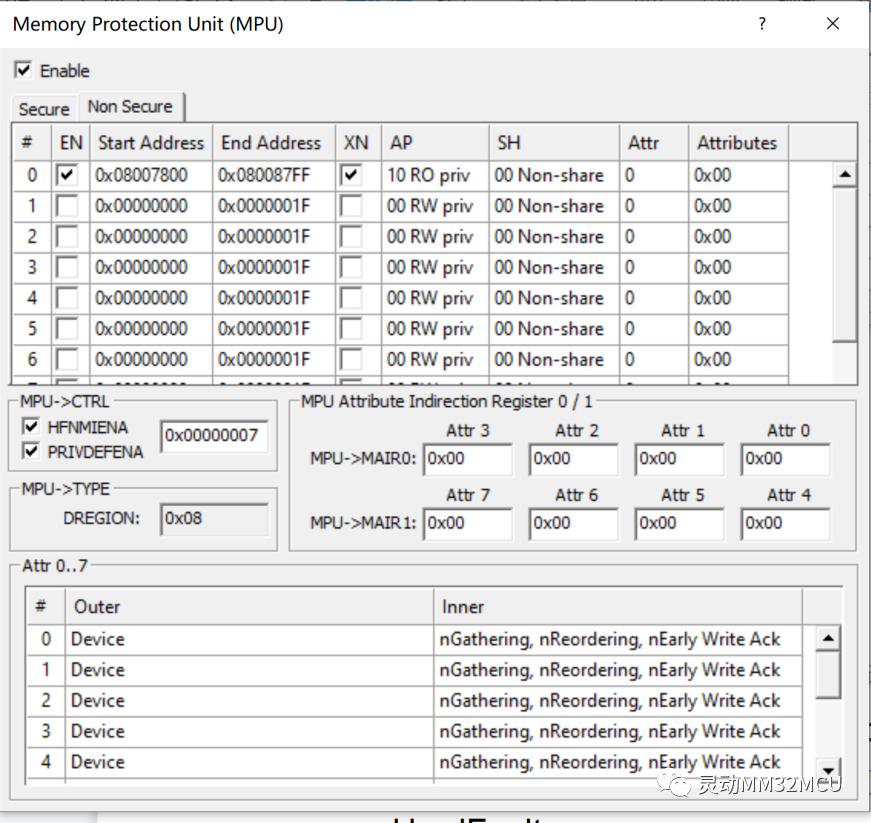
Define the func() function at the specified address 0x08007800. When the MPU is disabled, the function can be executed normally. By configuring the MPU to set the region 0x08007800 – 0x080087FF as non-executable, enable the MPU and then run the func() function again to observe the test situation. The test code is as follows:
void func(void) __attribute__((section(".ARM.__AT_0x08007800")));
void func(void)
{
    printf("Execute the function!\n");
}

void mpu_xn(void)
{
    //Inject code at 0x08007800
    typedef void (*test_func_t)(void);
    test_func_t test_func = (test_func_t)0x08007801;
    test_func();
    MPU_Cmd(MPU, DISABLE);

    //Enable MPU region0:0x08007800 - 0x080087FF
    //Read-only,Execution not permitted,Device memory
    MPU_SelectRegion(MPU, 0);
    MPU_SetRegionBase(MPU, 0x08007800UL, REGION_NON_SHAREABLE, REGION_RO_PRIV_ONLY, REGION_XN);
    MPU_SetRegionLimit(MPU, 0x080087FFUL, 0, REGION_EN);
    MPU_SetRegionAttr(MPU, 0, 0);

    MPU_HfnmienaCmd(MPU, ENABLE);
    MPU_PrivdefenaCmd(MPU, ENABLE);
    MPU_Cmd(MPU, ENABLE);
    printf("Test start:\n");
    //The test_func of 0x08007800 cannot be executed after MPU is enabled.
    //The hardfault will be triggered when the code is executed here.
    test_func();
    printf("Test over!\n");
}
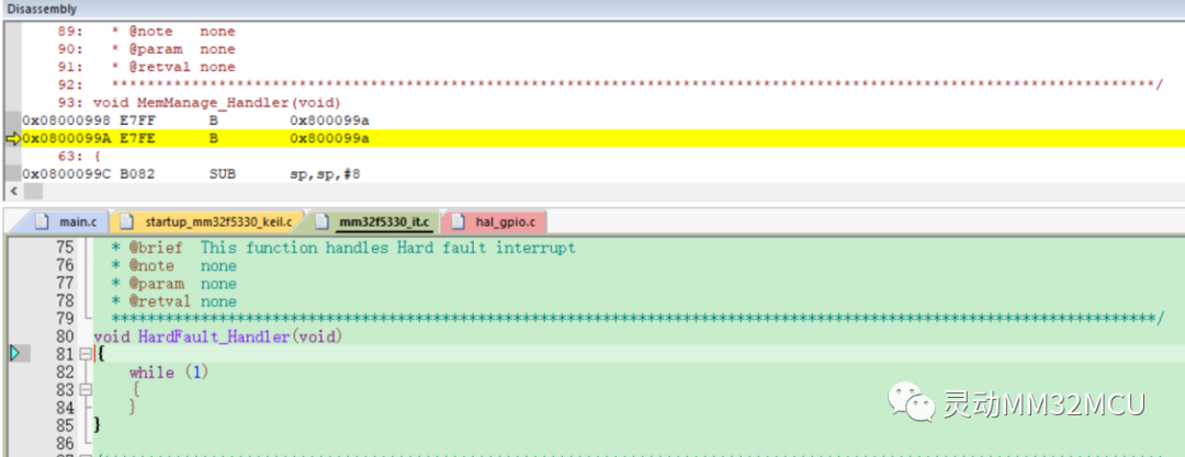
Simulation shows that the MPU configuration and code execution are consistent with expectations:
Serial port debugging assistant printout:

Calling func() once before printing “Test start” executes normally. After enabling the MPU, calling func() again triggers a HardFault, indicating that this code is not executable.
6
Conclusion
The MPU is a memory protection unit located in a programmable area within the memory, defining memory attributes and access permissions. Attempting to access illegal or disallowed memory addresses will trigger a HardFault exception. The MPU can enhance the robustness of embedded systems, making them more secure. In practical applications, depending on specific project needs, it is essential to choose whether the MPU should be set to default configuration or require some changes to meet application requirements.
Previous Highlights
Lecture 268 | MindSDK Application Basics – ADC Module Example
Lecture 267 | MindSDK Application Basics – SPI Module Example
Lecture 266 | Usage of Internal 1.2V Reference Voltage of MM32F0163D7P ADC
Lecture 265 | USB Audio Class (UAC) Audio Device Based on MM32F0163D7P
Lecture 264 | TinyUSB Application Based on MM32F0163D7P: Porting and Adding Devices (Part 2)
Lecture 263 | TinyUSB Application Based on MM32F0163D7P: Porting and Adding Devices (Part 1)
Lecture 262 | Music Player Experiment with I2S Interface Based on MM32F0163D7P
Lecture 261 | MindSDK Application Basics – TIM Module Example
Lecture 260 | mm32-2nd-bootloader Technical White Paper (9) – OTA Upgrade
Lecture 259 | mm32-2nd-bootloader Technical White Paper (8) – Advanced: Implementing Ymodem Code Update
Lecture 258 | mm32-2nd-bootloader Technical White Paper (7) – Performance Evaluation
Lecture 257 | Implementation of Single Cycle Sampling of ADC Injection Channel on MM32F5270 Platform
Lecture 256 | MM32G0140 I2C Driver EEPROM
Lecture 255 | Internal Clock Capture External HSE Clock of MM32SPIN0280
Lecture 254 | Mini-F0160 Implementing USB to Three Virtual Serial Ports
Lecture 253 | Setting Up Keil MDK Development Environment for MindSDK
Lecture 252 | Open Source Project: Mechanical Keyboard Based on MM32F0160 Microcontroller
Lecture 251 | Setting Up armgcc Compilation Environment for MindSDK (Windows Version)
Lecture 250 | mm32-2nd-bootloader Technical White Paper (6) – Summary and Precautions
Lecture 249 | mm32-2nd-bootloader Technical White Paper (5) – Compiling Programs to Run on QSPI Flash
Lecture 248 | mm32-2nd-bootloader Technical White Paper (4) – Designing a Simple 2nd Bootloader
Lecture 247 | mm32-2nd-bootloader Technical White Paper (3) – Designing a Download Algorithm for QSPI Flash
Lecture 246 | mm32-2nd-bootloader Technical White Paper (2) – Introduction to QSPI Peripherals
Lecture 245 | mm32-2nd-bootloader Technical White Paper (1) – Configuring Software and Hardware Environment
Lecture 244 | FlexCAN OTA
Lecture 243 | Downloading Executable Files to MM32F5 Microcontroller
Dynamic Micro Classroom Compilation
WeChat public account push mechanism revision
Are you frequently losing track of interesting updates?
Just two simple steps to light up“Star Mark ★”
Never miss any updates from Dynamic Micro!

About Dynamic Micro
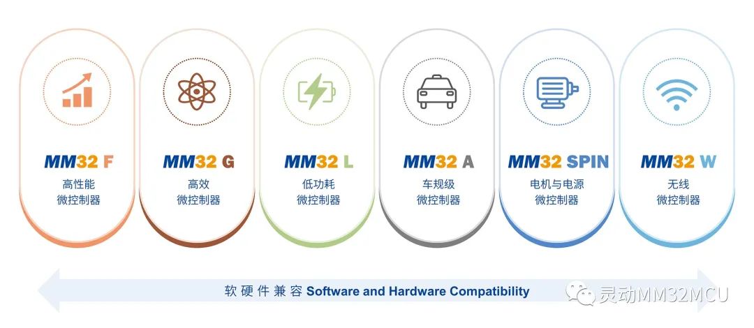
Founded in 2011, Shanghai Dynamic Microelectronics Co., Ltd. is a leading domestic supplier of general-purpose 32-bit MCU products and solutions in China. The MM32 MCU products developed by the company based on the Arm Cortex-M series cores have six major series: F/G/L/A/SPIN/W, with nearly 300 models in mass production and over 400 million units delivered, with nearly 100 million excellent products equipped with Dynamic MM32MCU delivered to customers each year, ranking among the top in the domestic general-purpose 32-bit MCU companies.
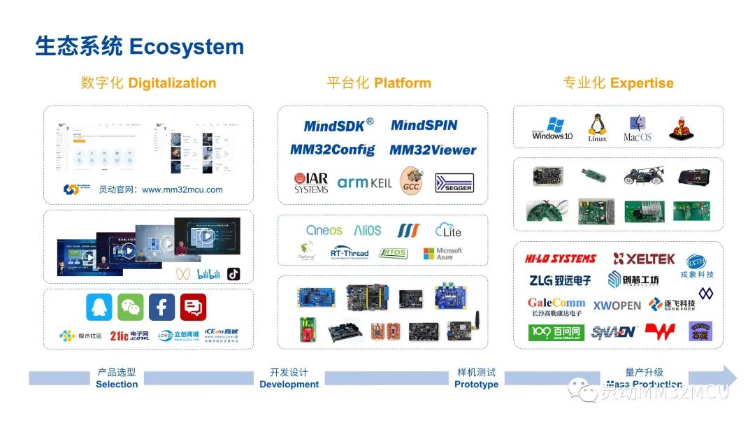
Dynamic’s customers cover applications in smart industry, automotive electronics, communication infrastructure, medical health, smart home appliances, Internet of Things, personal devices, mobile phones, and computers. Dynamic is one of the few domestic MCU companies that have received official support from Arm-KEIL, IAR, and SEGGER, and has established an independent and complete general-purpose MCU ecosystem. Dynamic always adheres to the spirit of “integrity, commitment, innovation, and cooperation” to provide customers with comprehensive support from hardware chips to software algorithms, from reference solutions to system design.
Dynamic Co., Ltd.
WeChat ID: MindMotion-MMCU


Long press to identify the QR code to follow us

MORE
Official website: www.mm32mcu.com
WeChat public account: Dynamic MM32MCU
Dynamic MM32MCU Technical Forum:
bbs.21ic.com/iclist-696-1.html